School of Innova on, Design and Engineering
MASTER THESIS
ELECTRONICS
30 HP, ADVANCED LEVEL
INTELLIGENT GRIPPER
Authors:
Company:
Supervisors:
Examiner:
Micael Östberg (
micael.ostberg@gmail.com
)
Mikael Norgren (
mnn07005@student.mdh.se
)
E eplan, Västerås
Mar n Ekström at MDH and Mathias Erlandsson at E eplan
Mikael Ekström
Abstract
The human hand is a great generic gripper as it can grasp objects of unknown shapes, weights and surfaces. Most robo c grippers in today's industry have to be custom made and tuned for each applica on by engineers, thus many man hours are required to get the desired behavior and repeatability. To be able to adapt some of the capabili es of the human hand into robust industrial robo c grippers would enhance their usability and ease the tuning by engineers once installed.
This thesis discusses the development of a robust intelligent gripper for industrial use, based on piezo sensors which have the ability to both sense slippage and detect objects. First, an experimental sensor prototype was developed successfully using an
amplifica on circuit and algorithms implemented in LabView. Secondly, a final
prototype containing a signal board, an FPGA board, a simple gripper with linear units and more robust sensor modules where developed.
The thesis further discusses which parts of the intelligent gripper that have been successfully implemented within the project me frame and which parts that needs to be further implemented, tested and improved.
Keywords: Intelligent gripper, slip sensor, FPGA, robot, industrial, robust
Sammanfa ning
Den mänskliga handen är en fantas sk universiell gripklo då den kan greppa objekt av okänd form, vikt och yta. De flesta gripklor i dagens industri måste vara specialgjorda och anpassas för varje applika on av ingenjörer och därmed behövs otaliga man mmar för a få önskat beteende och repeterbarhet. A kunna anpassa vissa av den mänskliga handens egenskaper ll en robust industriell robotgripklo skulle utöka dess
användarområde och lä a upp anpassningen för ingenjörer när den väl är installerad. De a examensarbete diskuterar hur en robust intelligent gripklo har blivit utvecklat for industriellt bruk baserad på piezo sensorer som har förmågan a känna av glidning och ini ell kontakt av objekt. Först, en experimen ell fungerande sensorprototyp
utvecklades med hjälp av en förstärkningskrets och algoritmer implementerade i LabView. Däre er utvecklades en slutlig prototyp innehållandes e signalkort, e FPGA-kort, en enkel gripklo med linjärenheter och mer robusta sensorer.
Examensarbetet tar vidare upp vilka delar som framgångsrikt blivit implementerade och vilka delar som behöver utvecklas y erligare, testas och förbä ras.
Acknowledgments
We would like to thank the following persons, in no par cular order, for a great deal of help and we could not have made it without them.
Mikael and Mar n Ekström at MDH for their many ps and tricks on how to proceed when obstacles where met. Ma as Erlandsson, Dag Lindahl, Liz Hoffman and Magnus Martebo at E eplan for helping us with various items such as project management, or-ders, contacts and mechanical solu ons. And of course Leigh Boyd for many hours of discussions of innova ve ways how to actually detect slip. We would also like to send gra tude to Johan Ernlund at Robotdalen for his help with robot integra on and Tomas Meurling at EIE who helped us with the linear units and controller. A thank to our very good friends Anton Widenius and Johnny Holmström should also be made for their en-durance when being asked countless of ques ons regarding electronics. And finally a huge thanks to our girlfriends for pa ence and understanding!
Table of Contents
Page
Abstract I
Acknowledgments II
List of Figures V
List of Tables VII
List of Abbrevia ons VIII
1 Introduc on 1 1.1 Background . . . 1 1.1.1 Robo c grippers . . . 1 1.1.2 E eplan . . . 1 1.1.3 Objec ves . . . 2 1.1.4 Delimita ons . . . 2 1.2 Related work . . . 2 1.3 Problem specifica on . . . 3 1.3.1 Mechanics . . . 3 1.3.2 Electronics . . . 3 1.3.3 So ware . . . 3 2 Method 5 2.1 Workflow . . . 5 2.2 Slip sensing . . . 5 2.2.1 Vibra ons . . . 5 2.2.2 Piezoelectricity . . . 6 2.2.3 Vibra on sensors . . . 6 3 Experiment 8 3.1 ISS sensor . . . 8 3.1.1 Sensor examina on . . . 8 3.1.2 Tes ng . . . 10
3.1.3 ISS sensor summary . . . 10
3.2 First prototype . . . 11 3.2.1 Signal analyzing . . . 11 3.2.2 Piezo disks . . . 11 3.2.3 Sensor modules . . . 11 3.2.4 Amplifying circuit . . . 12 3.2.5 Dual setup . . . 14
3.2.6 Slip sensing algorithm . . . 15
3.3 Final prototype . . . 19
3.3.1 System overview . . . 19
3.3.2 Mechanics . . . 20
3.3.3 Sensor modules . . . 21
3.3.4 Altera DE2 card . . . 22
3.3.5 Signal board . . . 22
3.3.6 FPGA . . . 25
3.3.7 Industrial robot integra on . . . 30
4 Summary 31 4.1 Conclusions . . . 31 4.2 Future work . . . 32 4.2.1 Signal board . . . 32 4.2.2 FPGA . . . 32 4.2.3 Sensor module . . . 32 4.2.4 System tes ng . . . 32 References 34
Appendix A VHDL source code 35
Appendix B Electronic schema cs 53
Appendix C Electronics Bill of Material 62
Appendix D Mechanical drawings 63
List of Figures
Page
2.1 Piezoelectric disk . . . 7
2.2 Piezoelectric film (Image courtesy of Measurement Specialists) . . . 7
3.1 Sensor boards examined . . . 8
3.2 Sensor layout . . . 9
3.3 Different sizes of the piezoelectric disk . . . 12
3.4 Experimental sensor module - top and bo om view . . . 12
3.5 Amplifica on circuit . . . 13
3.6 Setup with 1st and 2nd order filter . . . 14
3.7 Dual setup of the sensor modules . . . 15
3.8 Summing amplifier . . . 15
3.9 Small disk knock (le ) and slide (right) . . . 16
3.10 Middle disk knock (le ) and slide (right) . . . 16
3.11 Bigl disk knock (le ) and slide (right) . . . 16
3.12 Knock and slide waveforms. . . 17
3.13 Knocks and slides a er processing . . . 18
3.14 Final prototype setup . . . 19
3.15 Linear unit . . . 20
3.16 Gripper frame . . . 21
3.17 Sensor module . . . 21
3.18 Sensor module mounted on linear unit . . . 22
3.19 IAI ACON Posi on controller . . . 23
3.20 Signal board . . . 23
3.21 Op cal isolator . . . 24
3.22 FPGA overview . . . 26
3.23 State machine for Median filter . . . 27
3.24 State machine for Sorter . . . 28
3.25 Robot controller IRC5 with robo c arm IRB140 (Image courtesy of BK-TRONIC Electronic Engineering) . . . 30
B.1 Amplifica on circuit . . . 53
B.2 Voltage regulator circuit . . . 54
B.3 Motor controller circuit . . . 55
B.4 ADC circuit . . . 56
B.5 Complete signal board . . . 57
B.6 Signal board part 1 . . . 58
B.7 Signal board part 2 . . . 59
B.8 Signal board part 3 . . . 60
D.1 Sensor module . . . 63 D.2 Cover plate . . . 64 D.3 Gripper frame . . . 65
List of Tables
Page
3.1 Piezo disks tested . . . 11
List of Abbrevia ons
ABB Asea Brown Boveri Ltd.
ADC Analog to Digital Converter
CAD Computer Aided Design
CP U Central Processing Unit
DW T Discrete Wavelet Transform
F ET Field-Effect Transistor
F F T Fast Fourier Transform
F P GA Field Gate Programmable Array
GN D Ground
GP IO General purpose input/output
IC Integrated Circuit
IRLED Infra-Red LED
ISS Intelligent Sensor Systems
LCD Liquid crystal display
LED Light Emi ng Diode
M DH Malardalen University
P C Personal Computer
P CB Printed Circuit Board
P LL Phase-Locked Loop
P V DF Polyvinylidene fluoride
RAM Random-Access Memory
RC Resistor-Capacitor
SDRAM Synchronous Dynamic RAM
T CP /IP Transmission Control Protocol/Internet Protocol
V HDL VHSIC (Very High Speed Integrated Circuit) Hardware Descrip on Lan-guage
Chapter 1
Introduc on
1.1 Background
1.1.1 Robo c grippers
In today's industry robo c arms are used prac cally anywhere from manufacturing to the packaging process. Many of these tasks were previously performed by humans and to replace them fully, the robots need to be able to sense the world like a human does.
The robots are ge ng quite good at mimicking the mo on of the human hand [1] but
s ll lack the sensing ability that it possesses. Currently most of the robo c arms used in the industry are tailored to perform a specific task and cannot do anything outside the predefined boundaries. Most of them act on a simple open/close procedure with no proper feedback of the object grabbed. With some of the sensing abili es of the human hand added to them, they would be able to perform more complex and different tasks.
One of the crucial sensing abili es is to be able to sense if something is slipping. The first obvious thing this leads to is the ability to detect when an object picked is about to be uninten onally dropped, and have the chance to take ac ons to prevent it from happening. The other, not so obvious, possibility this gives, is for the robot to grab and hold an unknown object without knowing beforehand how much gripping force is needed to li and hold it, by sensing the actual slip of the object. This is much like how the human
hand knows the proper gripping force of unknown objects [4][5].
1.1.2 E eplan
The intelligent gripper master thesis is an ini a ve taken by E eplan in Västerås to pro-duce a first genera on prototype of a generic gripper. Most robo c grippers in today's industry have to be custom made and tuned for each applica on by engineers, thus many man hours are required to get the desired behaviour and repeatability. This increases costs greatly so by crea ng an intelligent generic gripper that can handle many
applica-ons, costs can be reduced significantly.
E eplan is a specialist in industrial equipment engineering and technical product in-forma on solu ons and services. The company was established in 1983 in Finland and is currently market leader in Finland and among the largest operators in the field in Sweden. Today the company consists of more than 40 offices and approximately 1,700 designers and specialists.
1.1.3 Objec ves
There are two main objec ve of this master thesis. The first is to create a prototype of a robo c gripper that is able to detect and prevent slippage. The second is to be able to pick sta onary objects placed with various offsets without moving them and s ll be able to place them at a certain specified loca on with micrometer precision. To divide the objec ves further, they can be divided into the following:
1. Inves gate the usage of exis ng sensor technique research at MDH (ISS) with a focus on gripping sensi vity, slip detec on and asymmetrical gripping ability. 2. Construct decision support u lizing fast electronic circuits that enables adap vity,
pressure sensi vity and responsiveness at slippage.
3. Mechanical construc on of the gripper. Focus on maintainability, produc on effi-ciency, gripping ability and gripping force.
4. Evalua on and tes ng.
5. Evaluate integra on of the gripper to exis ng robo c products at partner compa-nies.
1.1.4 Delimita ons
Although it is desired to have one generic gripper for every possible applica on, building one in reality is a very tough challenge and is hardly possible to achieve in 20 weeks with limited resources. The objects being picked can weigh from as li le as a few grams up to several hundreds of kilos with dimensions from a few millimetres up to a meter or more. This puts really high demands on the electrical and mechanical parts of the system to operate within those wide regions. Therefore this master thesis will focus on detec ng slippage and object offsets and limi ng the range of weight and size the prototype can handle.
1.2 Related work
As of now, there are a variety of different solu ons for detec ng slip, for instance C.H.
Chuang et. al. [2] implemented a slip sensor by utlizing thin PVDF-film with two
electrode-pairs moulded in silicone rubber and detec ng opposite spikes of the outputs when shear forces was applied to it. H. Yussof et. al. [10] showed that it is possible to detect slippage by u lizing op cal wave guide transduc on together with a CCD-camera for slip detec-on and silicdetec-one rubber as sensing elements. This approach makes it possible to detect
both normal and shear forces simultaneously. T. Maeno et. al. [6] developed a way to
detect slippage by integra ng several strain gauges into an elas c silicone rubber and measuring differences between the gauges. This made it possible to detect slippage just
before it occurred, so called incipient slippage. In the paper by S.Teshigawara et. al. [9]
another kind of slip detec on system is presented. This one is based on special features of pressure sensi ve conduc ve rubber. That is, rubber that is conduc ve when pressure
is applied to it. By having electrodes in a special pa ern underneath the rubber, certain micro-vibra ons that occurs just before slipping occurs could be detected.
The main drawback of all of these sensors is that they are not robust enough to with-stand all the forces and environmental factors ac ng upon them. Most of them rely on some type of elas c material beeing the gripping surface, while in the industry there are a number of grippers that requires metal as their point of grip. Some of them also have the disadvantage of only being able to detect slip in one direc on, which makes them unsuitable for a generic gripper.
1.3 Problem specifica on
The main goal of the project is to find a way to detect slip by researching and building a sensor capable of sensing slippage with high accuracy and at the same me be robust and scalable enough to handle most industrial applica ons. A gripper prototype will also be designed and manufactured so that the sensor can be evaluated realis cally. The gripper will have the ability to be integrated onto an exis ng industrial robot.
Three major parts need to be overcome in the project which are the mechanical con-struc on of the gripper module, the electronics for the sensors and so ware for process-ing the data gathered from the sensors and controllprocess-ing of the motors that open and closes the gripper.
1.3.1 Mechanics
The mechanical part of the system have the specifica on of being able to pick up objects with a simple form like a cylinder or a cube like structure. To be able to accomplish this at least two moving units co-linear to each other are needed. The weight of the gripper module must be within the tolerances of the robot that the module will be integrated on. Also the size must be taken into considera on during the design process so that it does not interfere with the set space that the robot arm can move in.
1.3.2 Electronics
The system must be able to control the motors that are moving the gripper and make the necessary signal processing to detect slippage. Sensors need to be developed that can detect slippage accurately and also be robust enough to be used in an industrial environ-ment. The sensor should be able to tolerate high forces ac ng upon it so the gripper that the sensor is integrated on can li heavy objects and also be sensi ve enough so it can detect objects with small mass.
1.3.3 So ware
The main objec ve of the so ware is to take care of interpre ng the electrical signals that is generated by the sensor and decide whether or not an actual slip has occurred. The so ware must also generate the correct signals to control the mo on of the gripper
itself, handle the communica on with the robot and provide feedback to the user of the current status.
To achieve slip sensing through so ware, some algorithms have to be developed to be able to differen ate a slip signal from sta c noise, knocks and other interference that might get picked up by the sensor. Tests have to be performed to see how a signal from slippage looks like from different sensor types, and from there the algorithms can be developed. Depending on what type of mo on is used on the gripper, communica on protocol and status type (display, leds, etc. ), appropriate so ware code has to be wri en.
Chapter 2
Method
This sec on describes which working method has been used to manage the project. The main subjects of the thesis is also described which are vibra ons and piezoelectricity. How to u lize the piezo electric effect to sense if something is slipping by measuring vibra ons in a material is also discussed.
2.1 Workflow
Agile method of the SCRUM type was used to organize and structure the project work flow. The project was divided into smaller tasks that spanned over one day or more that one team member had responsibility for. The tasks could be organized into three different major categories which were electronics, mechanics and so ware. A clipboard was used to move the tasks between different stages of comple on. They could either be ongoing which meant that someone was currently working on that specific task, finished or if a problem arouse around a task it could be put under the problem folder.
2.2 Slip sensing
In this sec on vibra ons and how to read them using a special kind of sensor that uses piezoelectric effect is explained. Both the physical phenomena of the sensors and the mechanical principle on how to u lize them.
One way to detect slippage is by measuring shear stresses in the material, and this is
the way the sensors from ISS, that is evaluated in (Chapter3), works. Another way and
the way chosen was to try and detect micro vibra ons caused by the slipping mo on, and dis nguish these vibra ons from other noises that might get picked up by the sensor. The sensor itself is of a piezo electric type which is sensi ve enough to detect the micro vibra ons and it comes in many varia ons suitable for accomplishing a robust solu on.
2.2.1 Vibra ons
Vibra ons are atoms in mo on, from air molecules to solid objects with ghtly packed atoms. When the atoms are forced into vibra onal mo on from a external force they oscillate around their equilibrium posi ons which can be described as a vibra on.
Two types of vibra ons exists which are called free vibra ons and forced vibra ons.
Free vibra ons occur when a external force put a object in mo on and let it vibrate freely.
One example of the free vibra on principle is the tuning fork, it will con nue to vibrate a er an ini al force like a hit has set it in mo on. Forced vibra ons are caused when a external vibra on is applied to a mechanical system like when a earthquake sets a build-ing in vibra onal mo on. The frequency of the vibra on in the forced system is the fre-quency of the applied mo on. In the free vibra on system the frefre-quency is the resonance frequency of the material that a external force is being applied on.
2.2.2 Piezoelectricity
The piezoelectric effect is an effect where certain materials, mostly semiconduc ng crys-tals, generates a charge when mechanical stress is applied to them. They also have the inverse effect, that is they deform when an electric field is applied to them. These two effects is due to the fact that the molecular structure of these crystals are not symmet-rically aligned. Every molecule also has one end that is more nega vely charged and the opposite is more posi vely charged. When mechanical stress is applied to the crystal, the molecules re-orients and a charge is generated.
2.2.3 Vibra on sensors
For detec ng a slide or knock performed on a solid material the piezoelectric effect can be u lized as the small movements will generate vibra ons in the material. Two types of sensors is described in this sec on which uses piezoelectricity to generate a charge which can be used to detect vibra ons.
Piezo disk
The first sensor evaluated u lizing the piezoelectric effect for detec ng vibra ons in a material is the piezoelectric disk. It consists of one semiconduc ng and one conduc ng
material with a piezocrystal in the middle (Figure2.1). The setup generates a difference
in charge between the semiconduc ng and conduc ng material when the disk is exposed to mechanical stress. The charge difference created can be used to detect any form of vibra ons near the piezo disk.
Piezo film
Piezo film [7] work on the same principal as the piezo disk. The film (Figure2.2) vibrates
freely in the air which flexes the semiconduc ng and conduc ng material making them compress and expand. This mo on generates a voltage over the materials which can be read and processed as an analogue signal.
Figure 2.1: Piezoelectric disk
Chapter 3
Experiment
3.1 ISS sensor
This sec on will discuss the sensor modules (Figure3.1) from ISS at MDH that supposedly
could measure both force as well as shear stress applied to it. These were the sensors that were originally planned to be used as primary sensors for detec ng slip. Some measure-ments were done to try and verify this. The knowledge about the sensor being tested was very limited beforehand at the school. No one knew how the four outputs were routed internally for instance, so it basically was a test from scratch of the sensors.
Figure 3.1: Sensor boards examined
3.1.1 Sensor examina on
The sensor was first examined in a microscope to see if any informa on could be found. Everything from a manufacturer name, part number or signal rou ng was of interest. It turned out that no numbers or other markings were there to iden fy which sensor module it might be. However it could clearly be seen how the internal rou ng was and how they were connected externally. A simple CAD-drawing of the sensor module can be seen in (Figure3.2).
Figure 3.2: Sensor layout
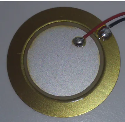
The sensor module actually consists of three sensors; two piezo films perpendicular to each other on the top and one more piezo electric sensor at the bo om. Underneath each of the sensors is a small hole to allow the sensors to flex. On top of the middle sec-on of the sensor module is some sort of see through material. Since this sensor should measure shear stress, the material is most likely some sort of rubber or silicon to allow it to flex when forces are applied to it. It is unclear if the holes underneath each sensor is also filled with this material, but most likely it is, to allow the sensors to move as part of the so material. This indicates that the two piezo films are used to measure shear stress while the third piezo electric sensor in the bo om is used to measure forces applied to it from above.
There were two sensor modules tested and both of them are mounted on a PCB, with some material covering them used as a pad to apply the forces and five external con-nectors. There are some differences between the two, the most no ceable is the pad covering the modules. One is made of some so silicone and the other is made out of glass. This is most likely to test how different hardness of the pad affects the sensor. The other not so no ceable difference between the two is that the small sensor modules themselves are mounted 180 degrees from each other on the two different boards. A pin configura on of the sensor boards can be seen below when viewed from the top,
pins facing upwards, from le to right: Sensor module with so silicone pad:
• Pin 1 - GND
• Pin 2 - Ver cally posi oned piezo film • Pin 3 - Not connected
• Pin 4 - Horizontally posi oned piezo film
• Pin 5 - Horizontally posi oned piezo electric sensor
Sensor module with hard glass pad:
• Pin 2 - Horizontally posi oned piezo electric sensor • Pin 3 - GND
• Pin 4 - GND
• Pin 5 - Ver cally posi oned piezo film
3.1.2 Tes ng
To try and see what kind of signals could be possible to get from the sensors they were connected to an oscilloscope. The first no ceable thing was that the sensor board with the hard glass pad didn't produce any signals at all when force applied to it and so it was assumed broken.
The other sensor board with the so pad did produce signals. However, even with a charge amplifica on circuit, only forces applied in the middle of the pad, directly above the sensor module, could be detected. This means the sensor cannot be used if the forces are ac ng anywhere but the center. No ce that no controlled approach, i.e. applying the exact same force, angle and speed on all the tests, were done. This was merely a test to see if any usable signals could be acquired at all.
It should be noted that since the sensors are of piezo electric type, they can not mea-sure absolute values, but only changes in forces applied to it.
The signal produced from the bo om force sensor was in the region of 50mV when hard pressure with the thumb was applied and around 200mV when a finger nail is pressed directly at the sensor module, without amplifica on.
The signals from the horizontally posi oned piezo film when thumb dragging hard horizontally on the surface was 50mV and with the finger nail 3-400mV.
The signals from the ver cally posi oned piezo film with thumb dragging hard ver -cally on the surface was roughly the same as for the horizontally posi oned one.
While tes ng the sensor board with amplifica on, it could be detected that at random occasions, the output from the module seemed to be short circuited, indica ng either a broken sensor or that this sensor is not stable enough to be used con nuously. This mostly occurred on the ver cally posi oned piezo film. This is what happened with all the outputs, all the me on the glass pad board, indica ng that is was broken right from the start.
3.1.3 ISS sensor summary
The sensor module itself has some interes ng features with the piezo sensors directly in contact with the above pad, giving it the ability to detect both force and shear stress applied to it (changes in them, not absolute). If the sensor board would be fully func onal without random hiccups, one could most likely be able to get the force applied and at what direc on the shear stress is ac ng by amplifying the signals, applying filters and make calcula ons based on the output of the different piezo sensors. No such filters or calcula ons were made in this test as it was only intended to see if the sensor itself did produce signals valuable enough to perform calcula ons on.
3.2 First prototype
3.2.1 Signal analyzing
To be able to dis nguish the occurrence of slippage from other forces ac ng on the sen-sor, several methods are examined. The first is to simply look at the output of the sensor and examine if there are any special kind of behavior that occurs right before and during slippage.
FFT is another way to dis nguish special characteris cs of a signal, not visible by only looking at the signal amplitudes as a func on of me. The FFT will convert the signal into the frequency domain which gives the possibility to see what frequency components are present in the signal. For instance, when listening to a motor that has a worn out gear, it might produce a different frequency component which is not present in a normal running engine of the same kind. By looking at the result from the FFT rather than the waveform itself, it is easier to dis nguish if any abnormal components are present in the signal.
3.2.2 Piezo disks
Three piezoelectric disks with different diameter and other characteris cs (Table 3.1)
were tested to check if the frequency component would differ between them using FFT. Two tests were performed on the piezoelectric disks that they could be subjected to dur-ing normal industrial opera ons. In the first test con nuous knocks were applied on the piezo disks to simulate something hi ng the system. In the second test a sliding mo on using solid plas c object over the disks were applied to give the sensa on of a object slipping.
To see if the frequency component would change when the disks were a ached onto a material, which they will be in the prototype of the sensor module, both tests were performed when the disks were hanging freely and glued onto a metal plate. Also, to see if the size of the metal plate or how the disks are a ached would interfere with the frequency output, two separate piezo disks with the same characteris cs were tested independent of each other so the data collected could be compared.
Small Middle Big
Manufacturer M urata M urata M ulticomp
Diameter (mm) 12 20 27
Resonance (kHz) 9 6, 3 4, 2
Capacitance (pF) 8000 10000 20000
Table 3.1: Piezo disks tested
3.2.3 Sensor modules
The main idea was to create a sensor sensi ve enough to detect slides from vibra ons, yet durable and scalable enough to withstand all kinds of strains and forces that might occur in industrial applica ons. The way chosen was to a ach the piezo disk on the back side of a piece of metal and rubber on the opposite side of the metal. This way the
Figure 3.3: Different sizes of the piezoelectric disk
disk itself won't be in any direct contact with any forces ac ng on the gripper and can easily be encapsulated to protect it from humidity, oil, solvents and such. The rubber can also be chosen freely to fit any specific needs, such as hardness, fric on coefficient, temperature range etc., without affec ng the output of the sensor (calibra on needed, but the principle of detec ng vibra ons remains the same).
Figure 3.4: Experimental sensor module - top and bo om view
(Figure3.4) shows the experimental sensor module from the top and bo om view.
Both the rubber and piezo disk are glued to the metal piece using an epoxy adhesive. To prevent the cable connec ng the sensor module to the amplifier from ac ng like an antenna and picking up electromagne c interference, a twisted pair cable with foil and braided shielding is used.
3.2.4 Amplifying circuit
Since the piezoelectric sensor produces a charge as an output, a charge amplifier, (Figure
3.5), is very well suited to amplify the signal. The name 'charge amplifier' is somewhat
misleading since it doesn't really amplify the charge itself, but rather transfers the charge to a feedback capacitor which in turn produces a voltage propor onal to the input charge.
Therefore the circuit acts like a current-to-voltage converter, making it easy to amplify and process the signal from the piezoelectric sensor.
Figure 3.5: Amplifica on circuit
The amplifica on of a charge amplifier is nega vely propor onal to the input
capac-itance of the piezoelectric sensor and the feedback capacitor (Equa on3.1).
A = −Cf Cp
(3.1) An amplifica on of around 160 was set to get signals good enough to perform
analy-ses on. This meant a value of 120pF for Cf was suitable.
The feedback capacitor and resistor also acts as a high-pass filter with the low cut-off
frequency seen in (Equa on3.2)
fL=
1 2πRfCf
(3.2) To remove some of the 50 Hz background noise, the low cut-off filter was set to 66Hz
by the use of a resistor value of 20MΩ for Rf.
A piezoelectric type of sensor has a high output impedance and requires an amplifier with high input impedance. Therefore a FET-type of opera onal amplifier is well suited. Other important factors when choosing an op-amp for this type of sensor is very low bias current and low noise. Several op-amps were considered, including Texas Instru-ment TL071, Na onal Semiconductor LF353, Burr Brown OPA129 and similar. Tests were performed with both the TL071 and the OPA129 and the choice fell on the Burr Brown OPA129, mainly due to it's ultra-low bias current of only max 100fA and low noise of 8nV/√Hz (TL071 has a bias current of 65pA and noise of 18nV/√Hz).
A prototype board (Figure:3.6) was made to test different kinds of filtering methods
could be alternated between two posi ons. The first jumper changed the first order fil-tering between 66 and 3000Hz cut-off frequency. The second jumper pin controlled the second order filter between the same frequencies as the first order.
There were one input and two output connectors on the board. One for the sensor and two for the filtering output. One output were on the first order filtering and the second output on the second order filtering.
From the prototype board a benchmark could be made to see roughly were the cut-off frequency must be and how high the filter order should be to get a good signal output from the piezo disk without irrelevant noise from certain frequencies.
Figure 3.6: Setup with 1st and 2nd order filter
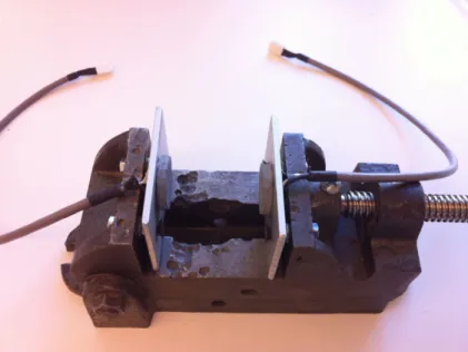
3.2.5 Dual setup
In the dual setup two sensor modules are tested together. The output signal from both modules are processed in both a differen al and a summing amplifier separately. A
charge amplifier (Figure: 3.5) is used to amplify the signal produced by the two sensor
modules. The test will try to dis nguish any special signals from external forces that cre-ate vibra ons in the whole system. When a force is applied on the whole system instead of directly onto a sensor module both sensors will pick up the vibra ons and output a similar signal which can be canceled out using either the summing or differen al ampli-fier. In theory the circuit will remove any external noise and leave the vibra ons created directly on the sensor modules intact.
The test bench consists of two sensor modules a ached onto a bench vice (Figure:
3.7).
The instrumental amplifier INA128P from Texas instruments is used for making the differen al amplifier. The amplifier is set in differen al mode and has no amplifica on.
The summing amplifier used during tes ng can be seen in (Figure:3.8). Two voltage
distur-Figure 3.7: Dual setup of the sensor modules
bance between the amplifica on stage and the summing stage as the amplifica on stage has a high impedance output but the summing stage has a low impedance output.
Figure 3.8: Summing amplifier
3.2.6 Slip sensing algorithm
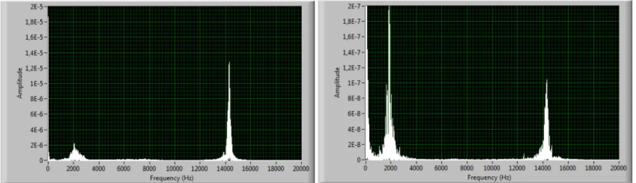
The first thing looked at was the FFT output of the three piezo disk to see if there were any special frequencies apparent in the signal during slipping compared to normal forces
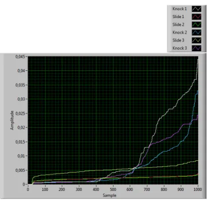
and knocks. As can be seen in (Figure3.9), (Figure3.10) and (Figure3.11) there exists
two major spikes in all of the tested piezo disk sizes at around 2kHz and 14kHz. It can also be seen that the spikes exists in both the knocks and slides, only the amplitudes are different. This indicates that there are no significant frequencies apparent only when something slips compared to knocks and it is most likely the resonance frequencies of the sensor module itself that is being picked up. Some tests were made to try and look
at differences in amplitudes, but the tests produced different results each me making it hard to use this approach.
Figure 3.9: Small disk knock (le ) and slide (right)
Figure 3.10: Middle disk knock (le ) and slide (right)
Figure 3.11: Bigl disk knock (le ) and slide (right)
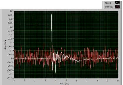
Since it was hard to differen ate the signals using FFT, waveform analysis was also tested. A no ceable difference between the waveforms produced from a knock and a
slide is seen in (Figure3.12)(the slide is amplified 10 mes more compared to the knock)
so further digital processing were made to produce an output telling if something is slid-ing or not.
Figure 3.12: Knock and slide waveforms.
The most obvious difference between the two is the very abrupt high spike produced by the knock compared to the more uniform "noise" produced by the sliding. The sec-ond is that a knock produces a significantly higher peak amplitude. These two main dif-ferences are the ones that are focused when trying to separate them digitally from each other. To get rid of any, rela vely, slower ac ng normal forces applied to the sensor, the charge amplifiers feedback capacitor and resistor values are changed so the circuit acts as a high pass filter with a cut-off frequency of 3kHz. Also another regular RC high pass filter with the same cut-off frequency is applied to the output of the amplifier, thus a 2nd order high-pass filter is effec vely created.
As can be seen in (Figure3.12), a knock and a slide can easily fit into a 10ms span. To
get good accuracy in the readings, a sampling frequency of 100kHz was chosen, thus 1000 samples are required to acquire 10ms of data.
The first thing done in the processing is to convert the signals into their absolute val-ues. This means, all the nega ve values are converted into their posi ve counterpart (i.e -4 becomes +4 etc.) and all the posi ve values remains the same. The next step is to apply a median filter with a large enough window size to make the signal smoother. The final step is to sort all the samples in increasing values to make it easier to compare the signals to one another no ma er where in the 10ms me frame the knock occurs.
(Figure3.13) shows 3 different slides and 3 different knocks in one graph a er the three
processing steps have been applied.
There it can be seen that there are some dis nct differences between the knocks and the slides:
• The slides are very flat • The slides climb fast ini ally
• The knocks have a steep curve in the end • The knocks have a higher maximum value
Figure 3.13: Knocks and slides a er processing
• The knocks have a low ini al value
By applying some threshold values for these dis nct differences, a fairly accurate way of detec ng slides within 10ms can be accomplished.
3.3 Final prototype
The main purpose of developing the final prototype setup was to move all the fun onality from a PC down into an embedded system, while also adding func onality for gripper control and robot integra on.
3.3.1 System overview
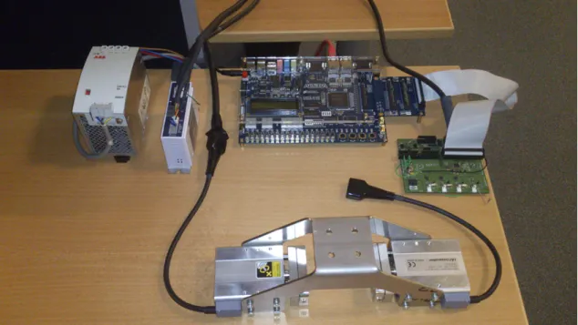
The final prototype setup consists of several parts (Figure3.14):
• Gripper (linear units + frame) • Sensor modules
• Signal board
• Altera DE2-115 evalua on board • IAI ACON posi on controller • 24V power supply
Figure 3.14: Final prototype setup
An all new signal board has been developed which handles sensor input and conver-sion and also converts signals to the linear unit posi on controller into correct format. All the algorithms from Labview have been ported into VHDL and runs on the Altera DE2-115 board, which also handles the communica on with the robot. All the signals needed for controlling the gripper are also generated in the FPGA.
3.3.2 Mechanics
IAI RCA2 linear unit
The linear units chosen to act as an opposing gripper is the RCA2-GD4N units (Figure3.15)
from IAI. They are of the type short length, double-guide, free mount type. They were chosen due to their compact size together with integrated motor and good performance.
They come in different versions and listed in (Table3.2) is the specifica ons for the one
chosen.
Figure 3.15: Linear unit
Motor size 20W
Feed screw Ball screw
Lead (mm) 6
Rated thrust (N) 33.8
Max payload horizontal (kg) 2
Max payload ver cal (kg) 0.5
Max speed (mm/s) 300
Stroke (mm) 30
Posi on repeatability (mm) �0.02
Dimension LxWxH (mm) 80x68x34
Weight (kg) 0.65
Table 3.2: RCA2 linear unit from IAI
Gripper frame
The gripper frame (Figure3.16) consists of one single laser cut and bent 3mm stainless
steel piece. Stainless steel was chosen for it's rigid proper es. It is very important that this piece does not flex when grabbing an object since this will affect the posi oning performance.
Figure 3.16: Gripper frame
The frame is designed to hold two RCA2 linear units facing each other making the as-sembly a simple gripper construcion capable of grabbing objects with two independately moving gripping surfaces. The top part of the frame is designed to fit directly onto an ABB IRB140 robo c arm.
3.3.3 Sensor modules
The final sensor modules (Figure3.17) is designed similar to the prototype, but with more
added features. They are specially designed to fit on the RCA2 linear units from IAI.
The modules consists of, just like the prototype, a base plate made out of aluminium for robustness and protec on of the sensor. To protect the sensor even more, a back plate is a ached which makes the en re sensor protected inside the module. This final prototype does not currently have an o-ring to protect the sensor from dust and liquids, but can be easily integrated with slight modifica ons.
Also incoroprated in this version is a connector to easily be able to replace the sensor module without the need to replace the en re cable running to the sensor. The sensor
module can be seen mounted on the linear unit in (Figure3.18)
Figure 3.18: Sensor module mounted on linear unit
3.3.4 Altera DE2 card
All the main features of the system is hardware accelerated on an Altera development board called DE2-115. It has an Cyclone 4 FPGA chip which contains all the algorithms controlling the system. A so -core processor is also present on the chip which handles the TCP/IP communica on.
Two GPIO connectors with 40 pins is used to connect with the signal board for send-ing logical signals to the motor controller circuit and fetchsend-ing the data from the ADC con-version. A special card is needed to use one of the GPIO connector as it has a special connector interface with 160 pins.
An LCD module exists on the Altera development board that is used for debugging the program when it runs through the different program loops.
The board also provides ethernet communica on with two ethernet PHY chips from Marvell called Marvell 88EE1111 Ethernet PHY chip. An ethernet transceiver is integrated in on the chips with support for 10/100/1000 Mbps.
3.3.5 Signal board
The signal board consists of four main parts which are an amplifica on circuit for am-plifying the signal from the sensors, voltage regulator circuit that converts between the different voltage levels on the board, an ADC for conver ng the analog signal from the
Figure 3.19: IAI ACON Posi on controller
Figure 3.20: Signal board
different sensors to digital signal that can be processed by the FPGA and a circuit for conver ng between different voltage levels between the FPGA and the motor controller. There are 3 voltage levels on the board. The main supply voltage is 24 volt which also is the logic voltage for the motor controller and the ADC has both 3 and 5 volt for the
logic. The Final prototype of the signal board can be seen in (Figure3.20). The list of
materials for the board can be found in the appendix sec on.
Amplifica on circuit
The amplifica on circuit used for the piezoelectric sensors was a charge amplifier. There is both a first order and a second order amplifica on stage as the first order is to sensi ve
to be used for slip detec on (to much noise/frequencies). The signal from the first order is used to detect ini al contact with the object that is going to be li ed up by the gripper module and the second order is used to detect slipping. The opera onal amplifier used
is based on the tests made during the experimental setup [Sec on3.2.4] which is the
OPA129U.
The capacitor used is a 120pF made in the material polystyrene for good insula on resistance and high tolerances. The feedback resistors used was of the type thin film as the material has good tolerances and have a low temperature coefficient. A low temper-ature coefficient is needed to ensure that the amplifica on of the sensors is stable during temperature changes in the surrounding environment. A schema c of the amplifica on circuit can be seen in (Figure3.5).
To insulate the signal from the piezoelectric elements in the sensor modules (Figure:
3.17) a guard trace has been added around the signal trace on the board. The guard trace
ensures that cross talk [8] from other signal routes on the board does not interfere. As
the signal strength may vary widely depending on the force exerted on the sensor module and how fast the object is sliding.
Voltage logic separator circuit
As the logic voltage levels is different between the FPGA and the ACON motor controller a circuit for conver ng the voltage levels is needed.
To separate the two different circuits an opto-isolator (op cal isolator) is used. The
opto-isolator [3] works by having a light emi ng media like a LED and some form of
pho-tosensor that triggers on the light that is being transmi ed from the light emi ng media. On the signal board a opto-isolator with an IRLED emi er and a photo-transistor as the photosensor is used. The photo-transistor works like an ordinary bi-polar transistor, the difference is that the collector junc on is light sensi ve which means that the base-current is generated when infra-red light from the IRLED is hi ng the photo-transistor.
Figure 3.21: Op cal isolator
The main func on of the opto-isolator is to isolate the FPGA circuit from the motor controller circuit because of the difference in logical voltage level. As the FPGA circuit uses a 3V logic signal and the linear driver that controls the motors on the gripper module uses 24V a opto-isolator is used as a switch to convert between the two voltages. When the FPGA chip sends a high logical signal it closes the circuit on the motor controller side and a logical high with 24V is generated. The ACPL-247-500E optocoupler is used as it can handle the voltage constraints and has four optocouplers in the IC which saves space on the main PCB.
Analog signal conversion
All the calcula ons and processing in the system is done on the FPGA which can not han-dle analog input signals so the signals from the sensor modules need to be converted into digital signals. An ADC is used to do the conversion. The ADC needed to convert eight different signals in parallel so an ADC with eight independent channels with simul-taneous conversion is chosen; the Maxim 1322ECM. During the experimental setup the output from the sensors never got over 12V and during normal opera on the voltage was around 2V. Each channel on the ADC has a tolerance of 5V but can withstand voltage spikes of up to 16,5V which mean that no voltage protec on circuit is needed between the sensors and the ADC IC circuit.
Voltage regulator circuit
There are three main voltage levels on the signal board which are 3V, 5V and 24V. 24 volt is needed to operate the ACON motor controller, 5V for the ADC circuit and finally 3V for the digital part of the ADC and the communica on between the FPGA and the ACON motor controller using the opto-coupler. An LM340T IC circuit was chosen to regulate the input voltage of 24V to 5V. To get 3,3V a linear voltage regulater named AP7313 is used which converts 5V to 3,3V. No heat-sink is needed to cool down the voltage regulator as the ground plane will instead dissipate the heat generated during the conversion. To prevent any interference from the voltage regulator on the ground plane, which other components are also connected to, a guard trace has been added around the regulator. The guard trace works as an insulator to prevent any noise from reaching the other com-ponents.
3.3.6 FPGA
Some sort of main processing unit was needed to process the sensor data, control the gripper and communicate with the robot. For this purpose an FPGA was chosen due to its great parallell processing capabili es.
All the func onality previously implemented in LabView has been ported into the FPGA, that is the actual slip detec on algorithms. Besides that the FPGA has also go en the responsibility to generate correct signals to the ACON linear unit posi on controller to be able to control the gripper. Finally it is also the unit responsible of communica ng
with the ABB robot. An overview of the FPGA-system can be seen in (Figure3.22).
As shown in the picture, a pipelined design has been used which means data is being processed in different units in series where data is sent from one unit to another. As an FPGA can do several things in parallel this means that not only is it possible to run two parallel pipelines at the same me, it can also process different data in each unit in the pipeline at the same me.
Each and every module listed below have been simulated in ModelSim to verify their func onality.
Figure 3.22: FPGA overview
ADC controller
The ADC-controller has the task of making sure the sensor data is retrieved correctly from the ADC on the signal board so it can be further analyzed down the pipeline. The ADC requires a number of control signals to accomplish this, such as ini aliza on, conversion and sending data.
The ADC controller is configured to retrieve four channels simultaneously at a rate of 100.000 samples/sec. The sampled channels are then sent out in series from the ADC with each channel containing 14 bits of data. The controller also has the ability to switch between first order filter data and second order filter data.
The way the controller works is to first setup which channels it should retrieve. Once this is done, it con nuously requests the ADC to take a sample, waits for conversion to finish, and then requests the data from the ADC and finally outputs it to the next step in the pipeline.
Linear unit controller
To be able to interface with the posi oning controller (Sec on3.3.4) of the linear units
(Sec on3.3.2), a special module has been wri en to address this. This module generates
signals such as the pulse train, homing signal and servo on and at the same me reads signals from the linear unit controller such as servo on, posi on complete and alarm.
po-si on of the gripper. It does so by having an internal parameter that is increased or decreased every me a new pulse train is sent to the unit.
The module consists of two state machines. The first one takes care of the ini aliza-on of the linear unit caliza-ontroller and homing signals.
The other state machine waits for an input command, interprets it, generates a pulse train and waits for the mo on to complete. This one also keeps track of the current posi on of the gripper and makes sure that it doesn't try to move the gripper out of it's mechanical boundaries.
Median filter
The median filter is implemented to use the current sample value together with the 20 previous values to form the window to process. When there are no previous values, the window is filled with zeros. This makes the total window size 21, which means that a er the window is sorted, value number 11 is the median value to pass on to the next step in the pipeline. Since a median filter operates with smaller windows of an en re sampling sequence, wai ng for the en re sampling sequence before processing is not necessary since the filter can process the values one by one. This makes it ideal for a pipelined structure. To accomplish the median filter algorithm, a state machine (Figure
3.23) is implemented in this module. A buffer array of the last previous 20 values is used
together with another array that is used for sor ng.
Figure 3.23: State machine for Median filter
The first state simply waits for new incoming data to arrive. As soon as it arrives, the state is changed to the next. This state shi s all values in the buffer array one step and inserts the newly arrived value into the array. Now this array contains the last 20 values together with the newest one. Once the shi is done, the state changes once more to where the sor ng takes place. Here the sor ng array ini ally contains a copy of the buffer array which gets sorted in increasing values. The sor ng algorithm here is of a bubble sort type, but u lizing the parallelism of the FPGA to make several comparisons in parallel. Thus the sor ng can be done in only 21 clock cycles to finish, making it very fast and efficient. As soon as the sor ng finishes, the state is changed to the next. This state updates the output with the calculated median value and a switch to the first state is done to start the process all over again.
Sorter
The sorter is implemented to be fast and efficient by using an inser on sor ng algorithm op mized for use in an FPGA. Only two clock cycles (80ns at a 50MHz clock) is required for the sorter to insert and sort the array with every new value that arrives. This is ac-complished due to the parallelism of the FPGA technology.
Figure 3.24: State machine for Sorter
(Figure3.24) shows the state machine used in the sorter. The first the sorter does
is to wait for a new incoming value to be sorted into the array. Once the value arrives, it switches immediately to the next state. This state simultaneously compares the new value with each and every other value in the array and finds where to insert the new value. It then switches to the next state, which simultaneously shi s every value smaller in the array than the new value one posi on and inserts the new value at the correct place. A shi is only necessary if a smaller number other than 0 exists, otherwise the shi is skipped. If this is the last sample in the sampling sequence, the output is updated with the values required for the slip detec on algorithm.
For example, if the sampling sequence consists of five samples and three have already been sorted in (6, 9 and 2), the array looks like this before a new value arrives: 0 0 2 6 9. Here is how the sor ng procedure will look like:
1. Wait for new value to arrive. 2. A sample with value 4 arrives.
3. Compare each value in the array with the new value simultaneously. This finds the inser on point to be at index 2 (index counted from 0 to 4) since 6 is the first number to be bigger than the new value.
4. Shi , if necessary, all values smaller than the new value (0, 0 and 2) one step to the le simultaneously. This will make the array to be 0 2 0 6 9. Since an FPGA can do several things in parallel, the new value is also inserted into the array at the same instance as the shi takes place. This will make the array to be 0 2 4 6 9.
5. If this is the last sample in the series, update output according to algorithm or start over again.
Slip detector
The slip detector is fairly simple in itself. It basically just contains all the different compar-isons that is required by the slip detec on algorithm. Whenever new data arrives from the sorter, the checks are made and a simple '0' or '1' is outpu ed indica ng whether slip or not is detected.
Object detec on
This part of the project was put aside due to me constraints and hasn't been fully im-plemented and tested. It is however a quite uncomplicated implementa on where a threshold value of the sensor signal is controlled and med. If the value is higher than a predefined value for a predefined me, an object is detected.
So CPU system
The ABB robot communicates externally using TCP/IP so an ethernet implementa on with TCP/IP had to be done. To reduce development me, a so CPU system was implemented to accomplish this. A so CPU system is a microprocessor system implemented using only logic synthesis. This means that it is possible to implement a microprocessor, memory, buses, peripherals etc. into an FPGA that is capable of execu ng regular C-code inside an FPGA, and at the same me be able to interact with VHDL-wri en code.
Since implemen ng TCP/IP-func onality in VHDL would be very me consuming and not within this projects scope, that approach was scrapped. Instead, since there are a lot of implementa ons for TCP/IP already wri en in C, a so CPU system is used.
The so CPU system was developed using Alteras SOPC builder and the following components were included in the system:
• PLL - For 100MHz system clock genera on • JTAG UART - For debugging
• NiosII CPU - Microprocessor
• SDRAM and onchip RAM - Memory
• Ethernet components - For ini alizing and accessing ethernet hardware • Parallell I/O's - For communica on with the rest of the system
This system enables all the hardware func onality needed to obtain working TCP/IP. The system also need C-code to run and this was wri en using NiosII So ware Build Tools for Eclipse. This IDE is a powerful tool that enables easy integra on of both Nichestack TCP/IP stack and the real me opera ng system needed for Nichestack to func on prop-erly, MicroC/OS-II.
To speed up development, a modified version of a demo called Simple Socket Server Design Example from the Altera was used. This design example sets up a simple TCP/IP server that can communicate with connected clients. This demo was modified to act as a client since the ABB robot acts as a server.
3.3.7 Industrial robot integra on
Due to me constraints, this part of the project was low priori zed. This means that there was only me to integrate a successful communica on link between the FPGA and the robot controller via TCP/IP.
The robot controller (Figure3.25), IRC5, was setup to act as a server and had a sta c
IP and port assigned to it. Once it was started up, it was programmed to wait for incoming connec ons. As soon as the FPGA established a connec on to the robot controller via a regular TCP/IP connec on setup, the FPGA was programmed to send a predefined string that the robot controller was wai ng for. Once the robot controller received the string, it sent back another predefined string to the FPGA to indicate a successful communica on link had been established.
Figure 3.25: Robot controller IRC5 with robo c arm IRB140 (Image courtesy of BKTRONIC Electronic Engineering)
Chapter 4
Summary
4.1 Conclusions
Quite early on in the project the scope had to be revalidated and changed as the sensor module from ISS that was intended to be used for detec ng slippage did not work quite as intended. A new type of sensor had to be developed for sensing slippage since the whole project depended upon such a sensor. The sensor developed detected slippage by sensing vibra ons through the use of a piezo element.
The new type of sensor module that has been developed can handle the stress of in-dustrial environments. The sensor is robust and can handle high forces ac ng upon the robo c gripper that it is fastened on. This is due to the fact that the sensing element of the sensor module does not need to be in direct contact with the object that the grip-per is li ing to detect slippage. The sensor can successfully separate slips from knocks and normal forces through the use of electronic filtering and so ware algorithms. Lab-View is a very powerful tool to quickly evaluate new algorithms and helped a lot during development of the system.
A mechanical gripper has been developed that can be used to verify the func onality of the newly developed sensor. It has two linear units moving in opposite direc ons towards each other and can be fastened upon an IRB140 ABB robot.
An electronic pla orm has been built for controlling the gripper module and handle all the signal processing from the sensors. For all so ware calcula ons an FPGA was chosen as it would speed up the system and make different parts of the system run in parallel. The slip sensing algorithms were implemented in the FPGA, but needs further tes ng for verifica on. A successful connec on between the FPGA and the robot controller through TCP/IP was also set up.
Many hours were spent rou ng the PCB as it contained many components and differ-ent func onality and there was also li le experience beforehand on how to route PCBs. The FPGA coding also consumed a lot of me since all drag-and-drop block-based algo-rithms used in LabView had to be ported to VHDL to allow for an embedded version of the system.
All in all, it was a very rewarding thesis as many aspects where covered from so -ware to electronics to mechanics in rela vely advanced depths. However, as a whole, the me span for the project where not very well suited for an advanced master thesis which should last for 20 weeks. This project needs roughly 5-10 more weeks to finish the prototype setup and complete all tests that need to be done.
4.2 Future work
This sec on will focus on how to get a fully func onal prototype system. The system should be able to pick up objects of unknown size and type of material by detec ng if the object is slipping or not.
Many parts need to be tested and verified to make sure that the complete solu on is working properly. Calibra ng the whole system integra on also need to be done as the current work only has verified that all the parts in the system is working as intended by itself but not how they will func on when merged together.
4.2.1 Signal board
The new signal board that have all the errors corrected from the first version must be manufactured and verified. The PCB should be redesigned to make space for the 40-pin connectors so you do not need to modify the male connector to make it fit.
Protec on should also be added to the amplifica on circuit on the board. Currently there is no voltage protec on between the piezoelectric element and the opera onal amplifier. During opera on the piezo disk can theore cally create very high voltage spikes that fries the surrounding electronics.
4.2.2 FPGA
There are a couple of things that has to be addressed for the FPGA-part of the system to be fully func onal. The pulse train output to the linear unit controller only works par ally. The differen al output looks OK when checked with an oscilloscope, but the linear unit controller responds erra cally when the pulse train is sent to it so this part needs more inves ga on.
One thing that was ini ally part of the original objec ves of the master thesis was the ability to sense ini al contact and from there calculate the offset of an object being grabbed. Due to me constraints, this part has not been fully implemented and tested yet. The remaining step is to test and calibrate the ini al contact part and implement the offset calcula on.
The slip sensing algorithm in the FPGA needs to be evaluated and calibrated to work with the new sensors.
4.2.3 Sensor module
Interference can occur when the piezoelectric element is in direct contact with a metal surface. Precau on has not been taken to ensure that the piezo disk is isolated from any metallic surface. Some non-conduc ve material can be used to prevent any interference.
4.2.4 System tes ng
The signal board has the ability to use four sensors simultaneously, two for sensing slip and object detec on and two for detec ng external noises that might cause interference in the slip sensing signals. The two external sensors has not been implemented and tested
yet and needs to be evaluated to inves gate how much external noise will affect the slip sensing algorithms.
Not much tes ng has been made with the actual robot integra on and a fully func-onal integra on has to be implemented. A movement scheme has to be defined for the robot to be performed. Also the communica on sequence has to be wri en both for the RAPID code on the robot controller side and the so cpu system on the FPGA side.
As of now, no complete tes ng has been made on the whole final prototype setup with all systems running. This is manly due to the fact that the individual parts of the system has not been fully tested.
References
[1] Antonio Bicchi. Hands for dexterous manipula on and robust grasping: a difficult road toward simplicity. IEEE Transac ons on Robo cs and Automa on, 16(6):652--662, 2000.
[2] C.H. Chuang, Y.R. Liou, and C.W. Chen. Detec on system of incident slippage and fric on coefficient based on a flexible tac le sensor with structural electrodes. In
Solid-State Sensors, Actuators and Microsystems Conference (TRANSDUCERS), 2011 16th Interna onal, pages 2863 --2866, june 2011.
[3] Ian Hickman. Analog Circuits Cookbook, Second Edi on. Newnes, 2st edi on, 1999. [4] R.S. Johansson and G. Westling. Roles of glabrous skin receptors and sensorimotor memory in automa c control of precision grip when li ing rougher or more slippery objects. In Experimental Brain Reseash, volume 56, pages 550--564, 1984.
[5] R.S. Johansson and G. Westling. Signals in tac le afferents from the fingers elici ng adap ve motor responses during precision grip. In Experimental Brain Reseash, volume 66, pages 141--154, 1987.
[6] T. Maeno, S. Hiromitsu, and T. Kawai. Control of grasping force by detec ng s ck/s-lip distribu on at the curved surface of an elas c finger. In Robo cs and
Automa-on, 2000. Proceedings. ICRA '00. IEEE Interna onal Conference Automa-on, volume 4, pages
3895 --3900 vol.4, 2000.
[7] Measurement Special es, Inc., 950 Forge Avenue Norristown, PA 19403. Piezo film
sensors Technical manual, rev b 02 edi on, 4 1999.
[8] Henry O . Electromagne c Compa bility Engineering. Wiley Publishing, 1st edi on, 2009.
[9] S. Teshigawara, K. Tadakuma, A. Ming, M. Ishikawa, and M. Shimojo. Development of high-sensi vity slip sensor using special characteris cs of pressure conduc ve rubber. In Robo cs and Automa on, 2009. ICRA '09. IEEE Interna onal Conference
on, pages 3289 --3294, may 2009.
[10] H. Yussof, J. Wada, and M. Ohka. A new control algorithm based on tac le and slippage sensa on for robo c hand. In World Automa on Congress (WAC), 2010, pages 1 --6, sept. 2010.
Appendix A
VHDL source code
A.1
Median filter
−−−−−−−−−−−−−−−−−−−−−−−−−−−−−−−−−−−−−−−−−−−−−−−−−−−−−−−−−−−−− −−−−−−−−−−−−−−−−−−−−−−−−−−−−−−−−−−−−−−−−−−−−−−−−−−−−−−−−−−−−− −− Filename : M e d i a n _ f i l t e r . vhd −− −− Date : 2012−07−10 −− −− D e s c r i p t i o n : Median f i l t e r implemented i n VHDL −− −− Authors : M i c a e l Ö s t b e r g and M i k a e l N o r g r e n −− −− P r o j e c t : P a r t o f I n t e l l i g e n t G r i p p e r m a s t e r t h e s i s −− −−−−−−−−−−−−−−−−−−−−−−−−−−−−−−−−−−−−−−−−−−−−−−−−−−−−−−−−−−−−− −−−−−−−−−−−−−−−−−−−−−−−−−−−−−−−−−−−−−−−−−−−−−−−−−−−−−−−−−−−−− L I B R A R Y i e e e ; USE i e e e . s t d _ l o g i c _ 1 1 6 4 .a l l; USE i e e e . n u m e r i c _ s t d .a l l; USE i e e e . s t d _ l o g i c _ u n s i g n e d .a l l; USE work . I n c l u d e s .a l l; E N T I T Y M e d i a n _ f i l t e r I S P o r t( −− ================== C l o c k and r e s e t =================== clk_50_MHz : I N s t d _ l o g i c ; r e s e t _ n : I N s t d _ l o g i c ; −− ================== Sensor data i n ==================== s e n s o r _ D a t a : I N s t d _ l o g i c _ v e c t o r ( 1 3 downto 0 ) ; new_Data_Ready_I n : I N s t d _ l o g i c ; −− ================== Data out ===================== m e d i a n _ V a l u e _ O u t : OUT s t d _ l o g i c _ v e c t o r ( 1 3 downto 0 ) : = (o t h e r s = > ' 0 ' ) ; sample_Nr_Out : OUT s t d _ l o g i c _ v e c t o r ( 9 downto 0 ) : = (o t h e r s = > ' 0 ' ) ; new_Data_Ready_Out : OUT s t d _ l o g i c : = ' 0 ' ) ; END M e d i a n _ f i l t e r ; ARCHITECTURE M e d i a n _ f i l t e r _ r t l OF M e d i a n _ f i l t e r I S −− ====================== C o n s t a n t s ======================= c o n s t a n t A R R AY _SI ZE : i n t e g e r : = 2 1 ; −− ================= Type d e f i n i t i o n s ===================== t y p e i n t e g e r _ a r r a y i s a r r a y ( n a t u r a l r a n g e 0 t o ARRAY_SIZE−1) o f i n t e g e r r a n g e 0 t o 8 1 9 2 ; t y p e R u n n i n g _ s t a t e s i s ( W a i t _ f o r _ n e w _ d a t a , S h i f t _ d a t a , S o r t _ a r r a y , S e n d _ v a l u e ) ; −− =================== I n t e r n a l s i g n a l s =================== s i g n a l s o r t e d : s t d _ l o g i c : = ' 0 ' ; s i g n a l f i r s t : s t d _ l o g i c : = ' 0 ' ; s i g n a l b u f f e r A r r a y : i n t e g e r _ a r r a y : = (o t h e r s = > 0 ) ; s i g n a l a r r a y T o P r o c e s s : i n t e g e r _ a r r a y : = (o t h e r s = > 0 ) ;