Improvement of field of
vision in dirty
environments
-
A case study on Volvo wheel loaders
Master thesis
Advanced level, 30hp
Product- and Process development
Dennis Björnberg
Thesis nr:
Supervisor (VOLVO CE): Robert Sundkvist
Supervisor (Mälardalen University):Bengt Gustafsson Examiner: Sten Grahn
ABSTRACT
This master thesis was conducted at Volvo Construction Equipment at the cabs department in Eskilstuna, Sweden. The work comprises 30 credits and was carried out by Dennis Björnberg from Mälardalen University during the fall 2015.
Volvo Construction Equipment is one of the largest manufacturers of construction equipment and among their products are wheel loaders. The assignment involves an investigation and evaluation of today’s windshield and wiper system for large wheel loader which is in need of improvements as today’s solution has reliability issues. As a result the cab department wants new concepts and solution for next generation of wheel loader that considers the current solution issues. This project aims to develop new concepts which answer the research questions developed to guide the project. The executed development process consists of three phases; problem formulation, concept development and finally product development. The first phase, problem formulation involves literature studies, project definition and demand specifications to formulate and guide the project in the right direction. The second phase develops primary concepts and comparisons with competitors and other solutions in a benchmarking leading to a development of the final concept in phase three. The development process resulted in a wide concept solution consisting of a new shaped windshield, a wiper system adjusted to the new windshield and with new frameless wiper blades, a conceptual pneumatic air system to investigate if an air barrier can keep the windshield clean and a recommendation regarding hydrophobic coatings for windshield´s.
The development process resulted in a concept proposing a new shaped windshield system where the side sections is curved for a smooth transition between the sections and a modified wiper system with a wider wiping angle and more square
The conclusion drawn from the project it that it is possible to improve today’s solution to develop new conceptual solutions but almost all the performance originates from the windshield´s shape and curvature. The recommendations based on the conclusions include among others to further investigate the windshield´s shape and it effects in the wiper system, develop prototypes to further investigate the efficiency of a pneumatic system in dry environments as a replacement for wiping without fluids and to watch the development of new hydrophobic materials and coatings with better durability and lifetime.
ACKNOWLEDGMENTS
I would like to thank my company supervisor Robert Sundkvist (Manager Cab & Operators Environment) for the opportunity to execute this interesting thesis work at Volvo CE during the autumn 2015. I would also like to thank the entire cab department at Volvo CE in Eskilstuna for a welcoming atmosphere, rewarding discussions and advices during the project.
I would like to give an especially large thanks to Nawrous Mahmoud (Lead Engineer WLO CAB) for all the committed help, guidance and encouragement given during the project.
Finally I would like to thank my supervisor at Mälardalen University Bengt Gustafsson for guidance and feedback during the project.
ACRONYMS & ABBREVIATIONS
CAD Computer aided design MDH Mälardalen university
FMEA Failure Mode and Effect Analysis FOPS Falling Object Protective Structure GDP Global Development Process PDM Product Data Management ROPS Roll Over Protective Structure R&D Research & Development Volvo CE Volvo Construction Equipment
Content
1 Introduction ... 1 1.1 VOLVO CE ... 1 1.2 Project background ... 1 1.3 Problem formulation ... 1 1.4 Project Aim ... 1 1.5 Research questions... 2 1.6 Delimitations ... 2 1.7 Project directives ... 2 2 Research methodology ... 32.1 Product development process ... 3
2.2 Data collecting method ... 4
2.3 Tools ... 5
2.4 Product development methods and tools ... 6
3 Theoretical framework ... 9
3.1 Volvo CE´s Wheel loader ... 9
3.2 Overview of windshield´s and wiper systems ... 10
3.3 Windshield systems without wipers ... 13
3.4 Regulations and standards ... 15
4 Empiric study ... 17
4.1 Phase one - Problem definition ... 17
4.2 Phase two – Concept generation ... 21
4.3 Phase three – Concept development ... 33
5 Results ... 39
5.1 Final concept ... 39
5.2 Subsystems ... 40
5.3 Prototype testing’s ... 41
6 Analysis ... 43
6.1 Answers to the research questions ... 43
6.2 Evaluation of demand specification ... 44
7 Conclusions and recommendations ... 46
7.1 Conclusions ... 46
7.2 Recommendations... 47
9 Appendixes ... 52
Figures
Figure 1 – The product development process (Ulrich & Eppinger, 2008) ... 3Figure 2 - The Global Development Process (Volvo CE, 2007) ... 4
Figure 3 – Adapted product development process ... 4
Figure 4 - Wheel loader L180 (Internal document) ... 9
Figure 5 - Overview of wiper systems ... 11
Figure 6 - Sweep patterns ... 11
Figure 7 - Depression angle (Waken, 2015) ... 12
Figure 8 - Wiper area quality (internal document) ... 12
Figure 9 - Comparison between a smooth surface and the surface of a lotus leaf (Barthlott & Neinhuis, 1997, p. 6)... 13
Figure 10 - Contact angle (Griggs, 2012) ... 13
Figure 11 - ISO 5006 test circle (The International Organization for Standardization, 2006) ... 16
Figure 12 - CAD-model with illustrated wiper area ... 17
Figure 13 - Important visual parts (internal document) ... 18
Figure 14 - Mapping of important parts visible throught the front windshield ... 18
Figure 15 - View in dirty environment (internal document) ... 20
Figure 16 - Wiper blade moving outside of windscreen (internal document) ... 20
Figure 17 - Concept 1 ... 28 Figure 18 – Concept 2 ... 29 Figure 19 - Concept 3 ... 29 Figure 20 - Concept 4 ... 30 Figure 21 - Concept 5 ... 30 Figure 22 - Concept 6 ... 31 Figure 23 - Concept 7 ... 31
Figure 24 - Todays windshield´s curvature ... 33
Figure 25- Detail development, windshield ... 34
Figure 26 - Conceptual sweep area ... 34
Figure 27 – Prototype rig ... 36
Figure 28 - Final concept, windshield and wiper system ... 39
Figure 29 - Proposed windshield shape ... 40
Figure 30 - Proposed sweep pattern ... 40
Figure 31 - Nozzles from lechler ... 41
Figures
Table 1 - Demand specification ... 20
Table 2 - Function analysis ... 21
Table 3 - Benchmarking ... 22
Table 4 – Summary of benchmarking ... 23
Table 5- Pugh’s matrix, evaluation of windshield´s solutions ... 27
Table 6 - Pugh´s matrix, evaluation of cleaning system solutions ... 28
1
1 Introduction
This report covers a thesis work on advanced level commissioned by the cab division at Volvo Construction Equipment (Volvo CE) located in Eskilstuna.
1.1 VOLVO CE
In 1832 Johan Theofron Munktell founded what would become Volvo CE in Eskilstuna which is one of the oldest companies still active in producing and developing construction equipment. The company was a repair shop until 1906 when they started manufacturing their first vehicle and 1932 Munktell merged with a company funded by the two Bolinder brothers and AB Bolinder-Munktell were founded. During the following years the company gained a good reputation for their high quality. During 1950 AB Bolinder-Munktell were bought by Volvo group and today the Volvo group is one of the leading companies in manufacturing of trucks, buses, construction equipment and drive systems for marine and industrial applications.
1.2 Project background
The windshield solution and primary the wiper systems on today’s wheel loaders made by Volvo CE are in need for improvements as the system lacks in wiper quality of the sweep areas and reliability. There has been some investigation and development over the last machine generations as projects involving choices of wiper blades, motors and mechanical linkage has been carried out. The
manufacturing processes for the mechanical linkage have also been evaluated and improved but the reliability issues still exist in today’s wiper system.
As a result the cab department at Volvo CE wants new concepts and solutions for the next generation of wheel loaders that takes todays issues into consideration. The concepts also have the liberty to change the windshields shape and implement new methods and techniques for cleaning the windshield.
1.3 Problem formulation
The given problem was to analyze the current design and specify the needed sweep area for windscreen wipers for wheel loaders. From this analysis a new design for the wiping area should be recommended that minimize dirt spray and maximize sweep area and the primary field of vision. A design for new mechanics to achieve the recommended sweep area for the wipers should be constructed and presented together with new solutions.
1.4 Project Aim
The aim of this project is through analyze of today’s solution, competitors and research of windshield and cleaning systems investigate whether it is possible to improve the cleaning solution for drivers of Volvo wheel loaders. The project also aims to investigate if it is possible to increase and improve the primary field of vision together with improving the quality of the secondary field of vision for the operator.
Is it possible to improve today’s solutions and produce one or more concepts that can be implemented in the development of the next generation of Volvo CE wheel loaders?
2
1.5 Research questions
Three research questions were formulated to help guide the project without restricting or specifying it. The conclusion of this report should have answered the following research questions at the end of the project:
RQ1: How can the operator get an as “unlimited” view through the front windshield as possible? RQ2: How can the primary field of vision be increased?
RQ3: How can the secondary field of vision get an improved visibility?
1.6 Delimitations
In accordance with Volvo CE and Mälardalen University (MDH) delimitations have been determined. The thesis work consists of 30 credits which translate to 20 weeks with 40 hours of worktime. The time for the project is limited from 31 August 2015 to 15 January 2016 and is primary located at Volvo CE in Eskilstuna.
The project compromises of product development, construction, and 3D-modelling of the windshield, wiper system and new conceptual solutions.
Product development:
- The project consists of an identified problem from Volvo CE and takes no consideration of customer’s needs. The demands are the ones the client have determined and identified. Construction:
- The construction work refers to Volvo CE large wheel loaders in the range from L60 to L350 which shares the same cab.
- No work regarding programing and regulation of the system will be taken
- The definition of the eye point position are the median value defined by Volvo CE - The windshield´s interface against the A-pillars, roof beams should not be changed 3D-model:
- The product will primary be constructed and presented in CATIA V5
1.7 Project directives
The product development process shall take The Global Development Process (GDP) into account as a requirement from Volvo CE. Volvo CE main 3D development tool is CATIA V5 and the made concepts and result shall primary be constructed and presented in CATIA V5.
3
2 Research methodology
This project in form of a case study has been initiated on behalf of Volvo CE cab department. The project contains a broad study with qualitative primary and quantitative secondary data have been used to answer the research questions. The qualitative primary data collection has been done through field studies at Volvo CE in Eskilstuna and interviews. The quantitative secondary data have been acquired from printed sources and searches in web based databases as google scholar and SAE International.
The methodology in this project initiates with a broad information gathering to acquire knowledge in the problem area and what the latest science says in fields useful for the study. The information is utilized to determine the delimitations and goals which later will determine the demand specification. From the demand specification and the gathered knowledge, concepts are developed with support from product development tools and methods. The concepts are then developed and evaluated which leads to one final concept for further development. To assure the quality of the result the product development utilizes proven methodologies and tools. The following chapter describes the used methodology, development process and tools utilized to support and assure quality the project.
2.1 Product development process
There are many different ways of handling product development. In most cases there is useful to use a proven effective product development process to successfully execute the project. The product development process in this project is a adapted version of Ulrich and Eppingers development process from the book Product Design and Development (Ulrich & Eppinger, 2008) and Volvo CEs own development process, the GDP (Volvo CE, 2007).
2.1.1 Ulrich and Eppinger´s development process
The process builds around six steps as shown in Figure 1 proposed by Ulrich and Eppinger (2008). The process describes a methodology starting with planning and ending with production start and product launch.
2.1.2 The Global Development process
The GDP are also a process with six steps or stages made ensure customer satisfaction and competitiveness with an effective development process (Volvo CE, 2007). The process describes a methodology that starts with a pre-study and ends with a follow up as shown in Figure 2.
Planning Concept
development
Systemlevel
design Detail design
Testing and refinement
Production and ramp-up
4
2.1.3 Adapted product development process
As the aim for the project is a concept many of the steps such as industrialization or production and ramp-up are not relevant an adapted development process has been applied trough the project. The project focuses on a pre-study to find the problem formulation and researching new techniques, solutions for the problem and to develop a concept from these findings. As a result this project has been divided into three phases. Each phase covers different steps of the process and includes general methods and product development tools which strive to secure a qualitatively result. As shown in Figure 3 the last phase includes the final product development and after the phase the concept should be finished.
2.2 Data collecting method
In this project the primary data have been collected thought field studies at Volvo CE in Eskilstuna. The field studies are primary based on unstructured interviews and observations which were done to give the author view on the product, problem and processes the thesis includes. Unstructured interviews and observations were considered suitable as the author was stationed at cabs R&D department with access to product machines with today’s solution. The interviews were conducted in form of meetings and discussions with co-workers that have knowledge of the problem and field.
Figure 2 - The Global Development Process (Volvo CE, 2007)
Phase One - Problem formulation •Literature study •Theroretical framework •Project definition •Demand specification
Phase Two - Concept development
•Benchmarking •Funktion analysis •Concept generation
& koncept evaluation
Phase Three - Product development •System development •Prototype testing •Detail development •Simulations •Failure analysis
5 The following people have been interviewed; company supervisor and lead engineer WLO CAB (Cab & operators environment), Lead engineer ART CAB (Cab & operators environment) Engineer involved in development of wiper and windshield for small wheel loaders (common solutions), Engineer involved in project aimed to improve todays wiper system (Cab & operators environment), Engineer specialized on visibility and regulations (common solutions).
The secondary data was found from different internet based sources and were the information used in the literature review. This was considered to be suitable as the latest research and knowledge are easiest to find online in research and technical papers. Used databases and search words is further described in 2.3.1 Databases.
2.3 Tools
A number of tools and methods were used in the project to support and secure a scientific methodology. The used tools and its application are described below.
2.3.1 Databases
As a first step in the gathering of knowledge searches in databases have been done. The databases SAE International, InterRegs and Scopus have been used for research of relevant information for the project. SAE International contains a large amount of technical reports in full text format and stating itself as the ultimate knowledge source for mobility engineering (SAE International, 2015). InterRegs is an online library for vehicle regulations covering global vehicle safety and emission regulations (InterRegs, 2015).
The search word used in this thesis are, “Wiperless windshield”, “self-cleaning materials”, “lotus
effect”, “Hydrophobic coating”, “Windshield wiper”, “Wiper systems”, “pneumatic rain removal system”.
2.3.2 Product development software
In the projects Computer Aided Design (CAD) software and Product Data Management (PDM) software were used to support the product development. The used software’s and their applications are presented below.
CATIA V5
CATIA V5 is a CAD software developed by Dassault Systems and is used to construct and assemble the product in a virtual environment. The software is also developed to produce drawings for manufacturing (Dassault Systems, 2015). CATIA V5 is the CAD software used at Volvo CE and was therefore deemed suitable to use in the development process.
SmarTeam
PDM software´s is used to handle large amounts of data and information and SmarTeam is the used PDM software at Volvo CE. PDM systems are used to integrate information from CAD models and assemblies together with drawings, technical requirements and other information regarding the products. As a large amount of information is needed to be investigated and processed, the use of SmarTeam were deemed relevant to use.
6
2.4 Product development methods and tools
The used adapted product development process methodology in this project as shown in Figure 3 is presented below.
2.4.1 Phase one
The first phase, problem formulation aims to retrieve as much relevant information from primary and secondary sources as possible to achieve a broad base of knowledge to apply in the project. The phase also includes measures to limit and define the project width.
Project planning – Gantt-schedule
The key to effectively execute a project is planning. As the limited recourse in this project is time a Gantt-schedule was used to plan and distribute the given time between all the needed activities. The Gantt-schedule can be seen in appendix 1.
Pre-study
An initial pre-study was deemed relevant for the project where the goal was to understand and define the aim and delimitations of the project. The current solutions for the windshield and wiper system were therefore studied both in parts and in action. The wheel loader and its components could easily be studied in CAD-programs and drawings where they were studied to see the geometry, shape and assembly.
Field study
To investigate how the operator is affected by the windshield´s shapes, wiped area and where important visible parts are visible through the windshield a field study were deemed relevant. The field study was conducted on Volvo CE workshop and Customer Center in Eskilstuna.
Literature review
A literature review needs to be performed to raise the understanding and to be acquaint with the available knowledge in the field (Kumar, 2005). The review will also give a good foundation for the project as it will help with approach and methods supported by previous writings. The preformed work and arguments will therefore have support from previously proven knowledge (Bell, 2006).
2.4.2 Phase two
The second phase concept development is aimed to use the information from the first phase in idea and concept generation tools.
Benchmarking
The first step to a broad concept development phase according to Ulrich and Eppinger (2008)is to understand competitive products. Benchmarking is therefore used to evaluate solutions and functions in the same product segment as well as ideas and functions from other market segments. Different solution was evaluated to find benefits and limitations to use in the concept development. The evaluated solutions were identified through research in literature and internal discussions at Volvo CE.
7 Demand specification
To specify the demands in a structured way a demand specification was produced. The demand specification is the document specifying the demands and properties the product need to have in order to meet the customer’s demands and is to be used as a guiding document through the product development process.
In the final demand specification was used as an analysis tool in the end of the project to evaluate the final products design. Many of the demands could not be defined or were too difficult to define with a measurable value and their value were therefore given the value “Yes”.
Function analysis
To specify and investigate the actual functions of the product a function analysis was done. These functions is the divided in three levels, the main function defining the products man function, necessary functions that is needed to fulfil the main function and desirable functions which supports the necessary functions (Österlin, 2010). The analysis will also support the coming concept analysis as it defines what functions the product needs to contain.
Concept generating
The concept generating and concept evaluation were executed in two cycles. In the first cycle general conceptual solutions were compiled and evaluated and combined to one final general solution. The combined general solution was then developed further into several concepts.
The first concept generation work was based on compiled general conceptual solutions found in the pre-study, review and benchmarking. The solutions were categorized into different general solutions.
Brainstorming
One tool used to produce potential solutions or concepts are brainstorming. The tool can be used both in group and by individuals and according to Ulrich & Eppinger (2008)four guidelines that are useful for improving the search are:
1. Suspend judgment 2. Generate a lot of ideas
3. Welcome ideas that may seem infeasible 4. Use graphical and physical media
The brainstorming process is a central step in the product development process to generate new concepts and ideas. In this project the brainstorming process did not take regard to the limitations and delimitations for the product to broaden the possible solutions for the problem involving the field of vision of how to keep the windshield clean.
8 Concept evaluation
The concept evaluations in the product development process are vital pars as the concepts are evaluated against each other and the demands regarding the product. There are several different methods and tools to evaluate and eliminate concept
Pugh’s matrix
Pugh’s matrix is a matrix used to evaluate different concepts against each other based on de products demands. Every concept is evaluated against one reference concept. The concepts are listed in a table and are evaluated in different evaluation criteria’s if they surpass (+), are equivalent (0) or inferior (-) to the reference concept. The purpose with Pugh’s matrix is to fast get an evaluation of which concepts are the best and worth to develop further (Ulrich & Eppinger, 2008). The results from Pugh’s matrix together with discussions were the foundation of choosing the concept to be developed further.
2.4.3 Phase three
In the final phase that focuses on product development the final concept or concepts are chosen the development process focus into system and detail development of the affected components. Below the processes and methods used in phase three are presented.
System and detail development
The system development aims to define the major subsystems and interfaces and refine industrial design for the product (Ulrich & Eppinger, 2008). Following the system development is detail design and development that aims to define the components geometry, material and tolerances (Ulrich & Eppinger, 2008; Volvo CE, 2007).
Failure analysis
The possible risks and failures that can occur for a product can be investigated with a Failure mode and effects analysis (FMEA) to scientifically evaluate the product. The risk analysis tool evaluates different possible failures that can occur for the product and the effects they bring which them. The analysis results in recommended actions for all possible failures to minimize or eliminate the failures (Ulrich & Eppinger, 2008). The tool is one of the most important tools at Volvo CE as it verifies the quality, reliability and performance of the product (Johannesson, et al., 2013), it is deemed appropriate to apply this tool in the development process to ensure the developments quality. Prototype
A physical prototype allows testing and experimentation which gives the development a possibility to a deeper learning and if the product works (Ulrich & Eppinger, 2008). To test the function and effects of the proposed conceptual solution during different circumstances it were deemed suitable to manufacture a functional prototype in this project.
9
3 Theoretical framework
To get an understanding of how wiper systems work and why windshield´s and wipers are shapes as they are a theoretical framework are presented in the following chapter. The knowledge and framework are based on secondary information from a number of books, projects and research papers to investigate the “State-of-practice” and “State-of-art” in the projects field.
3.1 Volvo CE´s Wheel loader
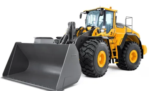
A wheel loader is a construction machine designed to move and load various materials and is commonly used on construction sites, timber yards and general working operations that need landscaping and material moving among others (Bengtsson, 1995). Volvo CE has a large range of wheel loader and the wheel loaders investigated in the project are largest wheel loaders ranging from L60 to L350. The operating weight for these machines is between 11 tons for the lightest L60 and up to 54 tons for the heaviest L350. There is typical divider in the large wheel loader range, L60 to L120 wheel loader are used in varying areas where almost all wheel loaders larger than L120 are used in producing manufacturing where they move large amounts of material. Common for all these loaders are that they are built with the same cab.
As the wheel loader has several different uses they have different attachments which is used for different operations. The most common used attachments are a variety of different buckets, forklifts and timber grapples. In Figure 4 a L180 is equipped with a general purpose bucket suited for handling a large variety of materials.
10
3.1.1 Operating environment based on industry sector
The wheel loader is used in a variety of environments and climates depending on the industry sector and intended applications. Some of the sectors and intended applications with typical environment and climate conditions are:
General construction – Executed under a wide variety of climates and temperatures. The environment can vary from dry dust to mud or snow. Often multiple vehicles and people moving in the same area.
Waste management – Most often done in a dry environment with much dust in the air.
Forestry - Executed under a wide variety of climates and temperatures. The environment can vary from dry dust to mud or snow. Often many high lifts when loading and unloading timber which requires a high and clean field of view.
Mining - Executed under a wide variety of climates and temperatures. The environment can vary from dry dust to mud or snow. Often multiple vehicles and people moving in the same area.
Agricultural - Executed under a wide variety of climates and temperatures. The environment can vary from dry dust to mud or snow.
A general rule for different environments is that dry environments with dust in the air need a dry cleaning system as wetting the windshield draws in more dust and creates mud on the windshield. For wet environments mud often splashes up on the windshield and requires a large amount of washer fluid for cleaning.
3.2 Overview of windshield´s and wiper systems
When operating a machine the field of vision is important as the operator on vision to gather 90% of the necessary information to maneuver the machine (Drury & Clement, 1978). As a result the quality and cleanliness of the field of vision are important. The first affecting element to the field of vision is the windshield.
3.2.1 Windshield´s
The windshield or front window of a vehicle exists to protect the operator or passenger from flying debris such as dirt (minerals, organic and biological), water, snow and ice. The windshield is generally made of laminated safety glass which consists of two glass sheets with plastic layers between (How Products Are Made, 2002; Pilkington, 2015a).
Initially the windshield´s shape was straight in one plane as it is easier to manufacture but in the 1950s the flat glass sheets where reheated and allowed to sag into curved molds. This technique was used to get a curved shape and the same technique is still used today. For more complex shapes the glass can be pressed between molds. The curved shape has benefits as it gives better aerodynamics and can improve the field of vision (Pilkington, 2015b).
There are some limitations to the shaping as the curved windshield is shaped before they are laminated together and need fine tolerances to fit together. There are also limitations to how far and sharp the curvature can be as it is molded from a flat sheet. A good example is to try and shape a piece of paper, the wrinkles that arises exist on the shaping of the windshield too (Eronen, 2011).
11 The shape on the windshield also affects the efficiency of the wiper system as the arm pressure and the wiper blades pressure may vary with the curvature. The angle between the wiper blade and the windshield is also affected by the windshield´s shape. Recommendation from suppliers and internal discussions states that the curvature on the windshield should be even or similar at the top and bottom for better quality of the wiper area and to lower wear on the wiper system.
3.2.2 Wiper systems
The windshield wiper was invented about ten years after the first automobile were made and is equipped on almost all motor vehicles today. The wiper system usually consists of wiper motors, cranks, wiper arms and wiper blades. The wiper system most often includes a washing system consisting of a pump, hoses, container for washer fluids and nozzles. Together these two systems form a complete cleaning system that removes water, snow and dirt from the wiped area on the windshield.
Wiper mechanics
There exist a large variety of wiper systems to keep the windshield clean. Some of the more common solutions are the five types of radial wiper systems are shown in Figure 5. These systems are commonly mounted on vehicles with a broad windshield and the most common is the tandem system which is controlled by a four link mechanism controlling the wiped area. In utility vehicle segment the opposed system is becoming more common but have a non-wiped area in the upper middle section of the windshield. For vehicles with a more square shaped windshield´s like busses, construction equipment and boats, a pantographic sweep pattern is made with two parallel arms compared to one singe arm which gives a radial sweep pattern as shown in Figure 6. The general rule for sweep patterns is windshield´s wider than it is tall are better wiped with a radial sweep pattern. For tall and narrow windshield´s a pantographic sweep pattern gives a better sweep pattern.
Figure 6 - Sweep patterns
12 The wiper system is most often used with a wiper arm which is used together
with a spring to press the wiper blade against the windshield. If the windshield is curved the wiper arm loses pressure against the windshield as the depression angle grows as illustrated in Figure 7. The angle should not exceed 10° from setup angle (Waken, 2015). If the angle is set to low the blade can scratch the windshield and damages the wiper blade as it is “digging” at the windshield´s highpoint. If the angle exceeds the recommended degree the wiper loses pressure and risks wind lift and no wiping and the quality may suffer. When designing the wiper system consideration to wear should also be taken. The wiping angle can rise up to 5° from its initial position (Waken, 2015) or 5 percent of the nominal sweep angle on both sides (Wexco industries, 2015).
Wiper blades
There are primarily two types of wiper blades today, the classic framed blades with 4-10 pressure points and a newer version of frameless wiper blades or beam blades depending on the manufacturer. The frameless wiper blade have been implemented int the automotive industry and the majority of new produced cars are fitted with these. Compared with a regular wiper blade the frameless wiper blade has a infinitive number of pressure points which gives a more even pressure along the whole blade. The frameless wiper blade is also supposed to give a better wiping quality on complex shaped windshield´s according to manufacturers (TRICO, 2015). Further is the primary development done and continued in materials of the blade which is the most important component of the wiper blade. Volvo CE have well defined technical requirements for the wiper blades wipe quality where after the wipe cycle the quality should be within Note 7-10 according to the table in Figure 8 (Volvo CE, 2015).
Figure 7 - Depression angle (Waken, 2015)
13 The angle of attack or the contact angle between the wiper blade and windshield greatly affect the performance and quality of the swiped area. Optimally the wiper blades angle should always have a 90° angle against the windshield´s surface so the wiper blade has the optimal angle of attack in both directions.
3.3 Windshield systems without wipers
There are large benefits if a technique can eliminates the wiper system function as no wiper arms and wiper blades would obstruct the field of vision. No limitations made by the wiper arms reach make it possible for larger clean areas. In this chapter three possible techniques or concepts are described that have been evaluated through the project.
3.3.1 Self-cleaning materials
When speaking of self-cleaning materials it often means a hydrophobic or super hydrophobic surface. The artificial made hydrophobic surfaces usually is trying to mimic the surface structures of self-cleaning organics and most often the surface structure on lotus leaves.
The phenomena with hydrophobic effects or reduced wettability were first described by Cassie and Baxter (1944) that described the fundamentals of water repellency. But it was not verified until Barthlott and Neinhuis (1997) investigated leaves that were artificially contaminated with various particles and subjected to rinsing water or
fog. On the water-repellent leaves the particles where completely removed by water droplets that rolled over the leaves surface carrying the contamination making in self-cleaning compared to a regular smooth surface as illustrated in Figure 9. The phenomena work due to the roughness, nanostructure and microstructure on the leaves makes the contact angle between the water drops and the surface force the water into beads that roll of the leaves.
The definition for a super hydrophobic surface is a contact angle larger than 150° between the water and the surface. As a result the water droplet has a minimal contact area with the surface. With an angle 160° the contact area between the surface and the droplet is only 2-3% of the droplet surface area (Rahmawan, et al., 2013). The benefits from super hydrophobic surfaces are great and some of the possible benefits from the super hydrophobic effect are anti-sticking of snow (Quéré, 2005), anti-reflective effects (Chang, et al., 2007) and self-cleaning windshield´s (Kako, et al., 2004; Chang, et al., 2007).
Figure 9 - Comparison between a smooth surface and the surface of a lotus leaf (Barthlott & Neinhuis, 1997, p. 6)
Figure 10 - Contact angle (Griggs, 2012)
14 The limitations in the technique today is that only hydrophobic coatings exist on today’s market and even if they improve the visual performance in vehicles (Sayer, et al., 1997) the effect diminish over time if the coating isn’t refilled. There have been good results to engrave the nanostructure and microstructure on iron but no transparent solution have been developed so far. The primary problem is that the micro and nanostructure is fragile, lotus leafs for example lose their hydrophobic effect if the leaf is exposed to friction but as it is a living organism the structure is repaired after a while. Available products today
There are primarily two types of coating on the market for windshield treatment today, silicone-based and fluorinated compounds. Silicone-silicone-based coating creates a smooth surface on the windshield but it does not create a chemical bond with the windshield which gives it low durability. Fluorinated compounds chemically bonds to the windshield and therefore it is effective longer compared with silicon-based coatings but the durability is still low.
3.3.2 Vibrating windshield´s
There exist concepts of self-cleaning techniques where the windshield is subjected to ultrasonic vibrations which move the water off the windshield. Already in 1988 Motoda Electronics Co., Ltd were granted a patent on ultrasonic wipers where rain and snow is removed with ultrasonic oscillation (Motoda, 1988) but their invention were never produced or implemented on any vehicle. McLaren is currently investigating and developing “ultrasonic force fields” to keep the windshield clean where debris will be repelled from the windshield which is plausible based on the same concept solution (Dron & Tobin, 2013).
3.3.3 Pneumatic rain removal system
Pneumatic rain removal systems have been implemented on military and commercial aircrafts for a long time but have not been implemented on manufactured ground vehicles even if several patents exist. On aircrafts, high temperature bleed air is usually drawn from the engines and is blown over the windshield to redirect and remove rain from the windshield (Federal Aviation Administration, 2012).
Several patents exist on how a solution consisting of pressurized air is implemented on cars to keep the windshield and lights clean. The general concepts is to fire burst of pressurized air to remove debris or to make an air barrier over the windshield surface so water, snow or other debris is redirected and prevented to reach the windshield (Gonzalez, 1998). One or the earliest patents on the concept is made by Ide which describe how the raindrops are scattered and blasted across the windshield (Ide, 1973).
15
3.4 Regulations and standards
In the following chapter the standards and regulations that have been used and taken into account in this project are described. In the project European standards have been used as they have the highest demands and regulations.
3.4.1 EN 474-1:2006+A4:2013
The standard EN 474-1:2006+A4:2013 are a safety standard that specifies the general safety requirements for earth-moving machinery. The standard is applied to reduce risks and hazardous situations during commissioning, operation and maintenance.
Regarding visibility and the operators field of view the standard states; “Earth-moving machines shall
be designed in accordance with ISO 5006:2006 so that the operator has sufficient visibility from the operator's station in relation to the travel and work areas of the machine that are necessary for the intended use of the machine. The travel mode as specified in ISO 5006:2006 is considered to be representative for testing visibility in both travel and operating modes.” (European Committee for
Standardization, 2013, p. 21)
3.4.2 EN 15573:2008
The European standard EN 15573:2008 specifies the appropriate technical measurements to reduce risks for road traveling earth-moving machines. The standard EN 15573 states the same as the standard EN 474 and referees to the standard ISO 5006 to ensure visibility necessary for travel on roads.
The standard also states that the front windshield must be fitted with a wiper system as it states; “The front window shall be fitted with motorised windscreen wiper(s) and washer(s). The area swept
by the wiper(s) must ensure an unobstructed forward view corresponding to a chord of the semi-circle of vision at least 8 m long within the sector of vision as described in ISO 5006. The wiper(s) shall have a frequency of ≥ 20 cycles/min” (European Committee for Standardization, 2008, pp. 15-16). The
standard also states that the system shall function between -18°C and +65°C. For machines where the maximum speed exceeds 30km/h only laminated windshield´s are permitted.
16
3.4.3 ISO Standard 5006:2006
The ISO standard 5006 (The International Organization for Standardization, 2006) describes a method to determine and evaluate the operator’s visibility and applies to earth-moving machinery operating on work sites and machines travelling on public roads. The Standard measures the visibility between a rectangular boundary at 1m from the machine and a circle with a 12m radius on the ground reference plane as illustrated in Figure 11.
The standard describes how many and how wide non visible fields are allowed to exist in each field depending on the wheel loaders operating mass. For wheel loaders under 10t two 700mm wide fields are allowed in sector A and no fields in sector B and C, for wheel loader between 10t and 25t the same fields are allowed or the fields in sector A can be exchanged for one 1300mm wide field. For wheel loader between 25t and 30t no masking’s are allowed in sector A, sector B and C are allowed to have one 700mm and one 1300mm masked field each, these values are also recommended for machines over 30t but the test circle radius may be larger.
17
4 Empiric study
In this chapter the execution of the GDP-process is described. The process follows the described process in chapter 3.1 and covers all three phases of this project.
4.1 Phase one - Problem definition
In this chapter the result from the pre-study that were conducted during the problem definition phase which includes an analysis of Volvo CE current solution and a demand specification are described.
4.1.1 Volvo CE current product
In the analysis of the current solution two categories were investigated, “general solution” and “field of vision and important visible parts”. The general solution investigates the shape and construction used today and what the problems and disadvantages with it are. Field of vision and important visible parts investigates the primary and secondary field of vision for the operator and what the necessary field of vision are operate the machine.
General solution
The current solutions consist of a tree part windshield joined with a black adhesive. The two side parts are flat laminated windshield´s that are connected to the A-pillars in the cabs framework. The middle section is the only wiped section, the section has a complex form and is double curved with a varying radius for the curves. The radius in the windshield´s top are larger compared to the bottom. The wiping system consists of a double arm system where each arm moves 60°. The wiper blade is 800mm long and the wiped area is a pantographic sweep pattern on the middle section of the windshield which have an sweep area of approximately 0,7 square meters. The Wiping system is mounted in two holes through the cabs front panel.
Fields of vision and important visible parts
Today’s cabs do not have a well-documented specification of the requirements regarding visibility and what the requirement of the primary field of vision is. From internal documents and discussions it were concluded that the primary field of vision is the area where the wiper sweep over today which is illustrated in Figure 12.
18 The primary field of vision should contain the necessary vision needed for the operator to maneuver the machine. Outside the primary field of vision are the secondary fields of vision where reduced visibility due to dirt are accepted but should be minimal. As the operator maneuver the machine there are some important parts or reference points on the machine that are especially necessary for the operator to safely operate and see the machines position. These parts are listed and illustrated in Figure 13 with red circles on the wheel loader.
An investigation on all the loader models compiled to a mapping on the visible important parts that are visible through the front windshield were done as illustrated in Figure 14. The illustration is made based on the result from the mapping in appendix 1.
Figure 13 - Important visual parts (internal document)
Figure 14 - Mapping of important parts visible throught the front windshield
19 The parts visual through the middle front windshield are the fork tips or bucket that are in the primary field which is wiped today, but when working in a high position almost nothing of the attachment is visible which force to the operator to bend forward to securely operate the machine. Some notable operations are loading/unloading timber from trucks and when using the forklift. The attachment quick lock is visible in the lower center of the wiped area or precisely under it, the front wheels is also visible in the middle section of the windshield but precisely outside the wiped area. The front fenders, rear fenders and rear corners are visible through the two side sections of the windshield. The rear fenders and the rear corners are visible in the rear view mirrors which are positioned in the top corners on almost all machines. The front fenders are positioned in the low corners of the windshield sections.
Problems/limitations
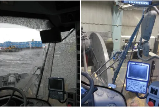
The variation of the windshield´s curvatures in all directions leads to extensive wear on the wiper system today and to the pressure in the upper part of the wiper patters loose pressure leading to lower wiping quality. Through internal discussions and recommendations from today’s supplier of the wiper system the radius in the top and bottom of the windshield should vary as little as possible for the wiper system to perform better and give a more even pressure against the whole windshield. As the current solution only wipes the middle section the two side sections of the windshield are not wiped as well as a part of the upper windshield. After some operating time in dirty environments the only clean area on the windshield is the area swept by the windshield wiper as shown in Figure 15. This leads to a smaller and narrower field of vision and many of the important visible parts are hidden by the dirt.
One other problem is that the wiper blades moves outside the middle section of the windshield and as a result get stuck so the operator needs to manually lift the wiper back onto the windshield. In Figure 16 the wiper blade have started to show tendencies to move over the black silicone bonding and outside the middle section of the windshield. This result in increased wear on the wiper blades and the momentum build up from the wiper gotten stuck breaks components in the wiper so the wiper system ceases to function. The problem seems to originate from extended wear on the system or that the tolerances on the mounting make the whole system to be mounted at an angle leading to the wipers turn positions is moved further towards one side.
20 The wiper system is used in a large variety of environments and all have different demands on the equipment. In wet environments the wiper system is used in a regular fashion to remove water, snow, ice and a variety of dry debris. In dry environments the wiper system are used to remove dust and other dry debris without usage of liquids as the liquids draw more dust to the windshield leading to a lower quality of the field of vision. Cleaning between shifts is often avoided as the machine needs to dry before use to avoid dirt sticking on the windshield´s wet surface.
4.1.2 Demand Specification
To specify the demands in a structured way a demand specification was produced. The demand specification defines what the final result should cover. The demands and values listed in Table 1 are retrieved from the system specifications for L60-L350 and relevant standards.
Table 1 - Demand specification
Function demands Value
Separate environments and keep pressure Yes Allow transparency over 75% in primary field of vision Yes Allow transparency over 70% in secondary field of vision
(when clean)
Yes Have a fitted mechanical wiper covering ≤ 8m in test circle according to ISO 5006
≤ 8m
Have fitted washers Yes
Remove water, snow and ice in primary field of vision Yes Remove debris(mineral, organic or biological) in primary
field of vision
Yes Remove water, snow and ice in secondary field of vision Yes Remove debris(mineral, organic or biological) in secondary field of vision
Yes
Geometry demands Value
Field of vision is consistent with ISO 5006 Yes
Figure 15 - View in dirty environment (internal document)
Figure 16 - Wiper blade moving outside of windscreen (internal document)
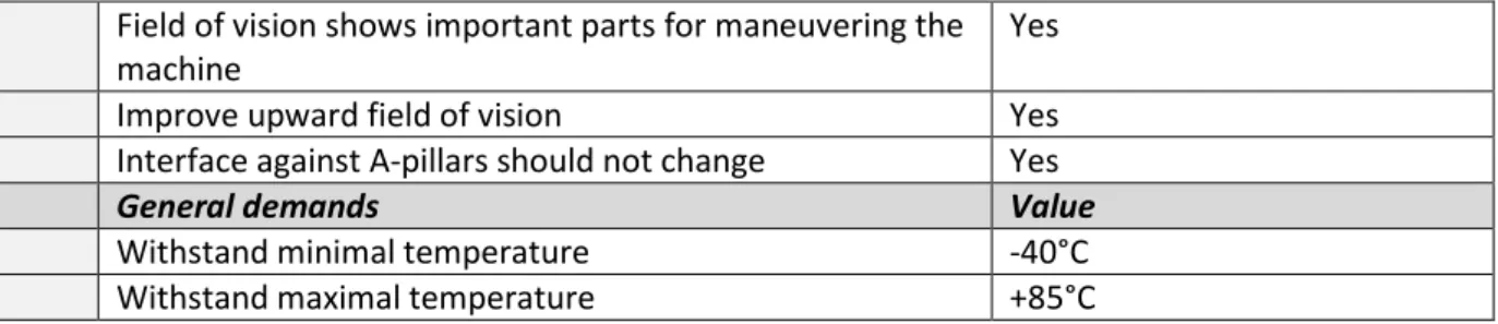
21 Field of vision shows important parts for maneuvering the
machine
Yes
Improve upward field of vision Yes
Interface against A-pillars should not change Yes
General demands Value
Withstand minimal temperature -40°C
Withstand maximal temperature +85°C
4.1.3 Function analysis
To support the concept generating and evaluating phase a function analysis were made. A structure of the functions making the solution work was broken down in different function categories. The main function was found to separate environments, to separate the operator from the outside. Sub functions to fulfil the main function were to provide a field of vision and keep this field of vision clean. The Windshield and cleaning solutions main function with the necessary sub functions and wanted functions is presented in Table 2.
Table 2 - Function analysis
Function Class Comments
Separate environments MF Enclose the cab space against the outside environment without hinder the field of vision Provide a wide field of vision N
Provide protection N Protect operator from debris Allow transparency N For visibility
Remove dirt N To keep the field of vision
Remove water, snow and ice N To keep the field of vision Provide structural integrity W
Provide large primary field of vision
W Allow easy
assembly/installation
W
Dry wiping/cleaning W Remove dust and dry debris without wetting the windshield´s surface
4.2 Phase two – Concept generation
In this chapter the empirical results from the applied methodology conducted during the concept generating phase.
The concept generating phase includes the steps conducted from the benchmarking, function analysis and concept generation of the different general solutions. The concept evaluation and choice of concept is also included in the phase. During the concept generation no consideration were taken directly to the demand specification or the function analysis.
22
4.2.1 Benchmarking
It is uncertain if the same problem with the windshield and the wiper system exist at other manufacturers also. But almost all researched competitors have a similar solution and designs for their windshield´s and wiper systems. There is one general solution all the different manufacturers of wheel loaders follow according to the benchmarking. All manufacturers use a windshield with tree parts, there are two general themes where CAT, Komatsu, LiuGong and John Deere have a relatively narrow center part and large and deep side parts. Liebherr and Doosan use a wider and middle part and as a result get a sharper bonding angle between the parts.
For the wiper system all the wheel loader manufacturers use some form of pantographic wiper system and all is mounted below the windshield. The backhoe loader also uses a pantographic wiper system but it is mounted above the windshield. Two interesting systems are brought up with the benchmarking which is the single controlled radial wiper blade used on Mercedes E-Class passenger cars where the wiper arm can control its length to optimize the wiped area. The other interesting wiper system brought up is the wiper system on busses where they have large wiper blades on a little curved windshield and uses frameless wiper blades.
In the following Table 3 and Table 4 the result from the benchmarking is illustrates and the conclusions from the solutions and competitors are shown.
23
Table 4 – Summary of benchmarking
Picture Company Modell (Type) Solution Benefits according to manufacturer
A CAT 950GC
(Wheel loader)
Three part windshield, single pantographic wiper system mounded below windshield. The wiper area is as wide as the bucket.
Wide view with flat and distortion free windshield. Excellent visibility of the bucket.
B Komatsu WA380-8
(Wheel loader)
Three part windshield, single pantographic wiper system mounded below windshield
Wide pillar-less flat glass for excellent visibility, wiper system covers large area.
C Liebherr L542
(Wheel loader)
Three part windshield, single pantographic wiper system mounded below windshield. The wiper area is as wide as the bucket.
Wide view of the working area.
D LiuGong CLG856III
(Wheel loader)
Three part windshield, single pantographic wiper system mounded below windshield
E Doosan DL220
(Wheel loader)
Three part windshield, single pantographic wiper system mounded below windshield. The wiper area is as wide as the bucket.
Large front glass surfaces and small window joints give excellent all-around visibility.
F John Deere 844K-II
(Wheel loader)
Three part windshield, single pantographic wiper system mounded below windshield. The wiper area is as wide as the bucket.
Spacious front glass, low-profile console, and large side allow unsurpassed 360-degree visibility.
G Mercedes E-Class (Passenger car)
Single part windshield, controlled mono wiper system
H Mercedes Tourismo
(Buss)
Single windshield, Opposite radial wiper system with “long” wiper blades
I Subaru Impreza WRX
STI (Passenger car)
Cleans the headlight with high pressure washer fluid. J Exair Super Air Knife
(Industrial application)
Cleans and redirects debris with high pressure air K Lechler Air nozzle
(Industrial application)
Cleans and redirects debris with high pressure air
24
4.2.2 Evaluation of existing solutions
As the traditional wiper solutions for wheel loaders are generally similar on all competitors other more conceptual solutions where also evaluated to investigate the benefits and limitations of the different solutions.
Type of solution Benefits Disadvantages
Single part windshield No joints Do not allow too complex shapes Hard and expensive to manufacture Two part windshield Allow deep shape of windshield Asymmetrical windshield or joint in
the center blocking the operators view.
Wiper blades should not move over joints.
Needs more wiper arms if all surfaces should be wiped.
Three part windshield Allow deep shape of windshield No joints in primary field of vision
Wiper blades should not move over joints.
Needs more wiper arms if all surfaces should be wiped.
Type of solution Benefits Disadvantages
Flat windshield Easy and cheap to manufacture Bad aerodynamics
Do not deflect rocks and debris as good as curved windshield´s No bending depth
Curved windshield Better aerodynamic
Wrap-around effect gives larger view
Stronger due to its curvature Smaller glass area for same view as flat glass
The wiper arm ned to move “uphill” Complex manufacturing process Can give unwanted optical effects
25
Type of solution Benefits Disadvantages
Pantographic sweep pattern
Verified solution for tall narrow windshield
High, parallel sweep pattern
Many linkages/moving parts
Radial sweep pattern Verified solution for wide windshield´s with two wiper blades
Many linkages/moving part
Opposite radial sweep pattern
Verified solution for wide windshield´s with two wiper
Many linkages/moving parts
Leaves the upper, middle part upswept Controlled radial sweep
pattern
Verified solution for wide windshield´s
Relatively sensitive mechanics
Type of solution Benefits Disadvantages
Traditional wiper blade Verified solution “only” 6 or 8 pressure points Several moving parts
Used together with washer fluid Beam wiper blade “infinitive” pressure points
Less moving parts
Developed for highly curved windshield
Used together with washer fluid
Self-cleaning technology
No wipers/wiper mechanics All glass is clean and gives “endless” primary field of vision No need for specific fuel/fluid
Water is needed to remove dust and dry debris
No mechanical cleaning High pressure washer
fluid
No wipers
All glass is clean and gives “endless” primary field of vision
Fluid residue possibly left after use No mechanical cleaning
Uses more fluid comparted to regular wipers
Wet the windshield´s surface Restricted amount of fluid Vibrating cleaning
solution
No wipers/wiper mechanics All glass is clean and gives “endless” primary field of vision Do not wet the windshield´s surface
No need for specific fuel/fluid
Unproven solution No mechanical cleaning Effective range is uncertain
Pneumatic rain removal system
No wipers/wiper mechanics All glass is clean and gives “endless” primary field of vision Do not wet the windshield´s surface
Redirect debris
No need for specific fuel/fluid
Unproven solution
Need additional power/air source No mechanical cleaning
26
4.2.3 Description and evaluation of general conceptual solutions
In the following section feasible general conceptual solutions are presented. The solutions are presented in an undefined order and not according to potential or feasibility. The general conceptual solutions are based on the existing solution to determine the direction of the development and narrow down the possible solutions for the concept development.
I – One part windshield
The windshield is manufactured in one single part so no joints are blocking the field of vision and the joint do not limit the possible sweep area for wipers.
II - Two part windshield
The windshield is manufactured in two parts and joint together with an adhesive. As there are several parts the depth of the windshield can be greater compared to if it is manufactured in one part and the assembly is easier with lighter parts. The joint are either asymmetrical or it is in the middle of the windshield.
III - Three part windshield
The windshield is manufactured in three parts and joint together with an adhesive. The manufacturing and assembly are easier compared to one or two parts windshield´s. The depths can also be greater compared to one part windshield´s and no joints are in the primary field of vision. The sweep area are however limited as a result from the joints.
IV – Mechanical wipers
Mechanical wipers are a proven effective solution which has been used during a long time. The wiper system can consists of both radial and pantographic sweep patterns. The concept consists of both regular wiper blades and the newer beam blades.
V – Self-cleaning windshield
The self-cleaning glass has high potential for large clean area as it is not limited to a mechanical arm and all the area is clean. There is also no moving part so the system is reliably. The disadvantages for self-cleaning glass are that it is relatively new and unverified technique. There are also problems with removing dry dirt and dust as the glass need water drops to transport the dirt and dust of the windshield.
VI – High pressure washer system
The high pressure washer system cleans the windshield and allows targeted cleaning in specified spots.
The disadvantages for the solution are that there can be residue from the washer fluid left on the windshield that are attracting dust and lowers the quality of the field of vision even more. It can also leave dirt on the windshield as there is no mechanical wiping.
VII – Vibrating cleaning solution
The vibrating cleaning solution consists of a regular windshield that vibrates. The vibrations hinder dirt and rain to stick to the windshield.
The disadvantages with the technique are the uncertainties as it is during development and no viable solution have been presented.
27 VIII – Pneumatic air system
The pneumatic air system removes liquids and debris with burst of air or creates a barrier that redirects or blows away liquids and other debris from the windshield. The disadvantages can be that more dust is blown in motion so a dust cloud surrounds the machine and it is an unproven solution for ground vehicles.
General conceptual solutions evaluation
The evaluation of the general conceptual solutions resulted in two tables there the first is comparing windshield solutions and the second evaluates cleaning solutions. The concepts chosen for further development were decided through internal discussions regarding the result in Pugh’s matrix, benchmarking and evaluating of existing solutions.
The first table evaluation general conceptual solutions for windshield solutions consist of three solutions where the concept with three windshield sections were selected as shown in Table 5 below.
Table 5- Pugh’s matrix, evaluation of windshield´s solutions
The general conceptual solution for the cleaning system the general solutions were many uncertainties existed regarding the general solutions as shown in Table 6. Three solutions were finally selected for further developments which were mechanical wipers, self-cleaning materials and air barrier as they can be combined and together fulfil all the requirements. The vibrating solutions were eliminated as too many uncertainties were found together with the high pressure fluid solution where the estimated result were deemed to be poor due to prototype testing’s conducted in previously projects at Volvo CE.
Demand I II III
Separate enviroments 0 0 0
Possiblity to wide/deep field of vision 0 + + Possiblity to wide/deep primary field of vision 0 - 0 Possiblity to high field of vision 0 + + Possiblity to high primary field of vision 0 0 0
Provide protection 0 0 0
Allow transparency 0 0 0
Allow easy assembly/installation 0 + +
sum + 0 3 3 sum 0 9 5 6 sum - 0 1 0 result 0 2 3 Ranking 3 2 1 Continue? No No Yes
28
Figure 17 - Concept 1 Table 6 - Pugh´s matrix, evaluation of cleaning system solutions
4.2.4 Description of final concepts
After a concept generating including the decided general solutions five concepts was deemed suitable for further investigation and development. The concepts are developed to allow as large and qualitative primary field of vision as possible
The concepts were designed according to the guidelines and recommendation regarding the shape and construction found in the literature and through discussions. The concepts were illustrated with sketches and are described and illustrated below.
Concept 1
The concept includes a three part windshield where the side sections of the windshield is flat and the middle section is double curved to give a wide and deep field of vision. The cleaning solution consists of a beam wiper blade system on the middle section similar to today’s solution. The side sections of the windshield´s have also one or two wiper each as illustrated in Figure 17. The type of wiper and wiper system is not defined.
The potential benefits with the solution are that the side sections get wiped compared with today and the side sections is flat so the wiping quality should be good. The potential disadvantages are that the middle section of the windshield has a complex shape similar to today’s solution so the wiper quality may have the same problem too.
Consequences for further development:
- Investigation and development of wiper/washer system - Development of wipers for side sections
- Investigation and application of hydrophobic coating
Demand IV V VI VII VIII
Remove dirt(mineral, organic or biological) 0 - - ? +
Remove water, snow and ice 0 + - + +
Possiblity to wide/deep primary field of vision 0 + + + + Possiblity to high primary field of vision 0 + + + +
Reliability 0 ? ? ? ?
Functionality with windshield solution 0 + + ? + Estimated quality for field of vision 0 - - -
-Allow easy assembly/installation 0 + + -
-Estimated matufacturing simplicity 0 0 0 -
-sum + 0 5 4 3 5
sum 0 9 1 1 0 0
sum - 0 2 3 3 3
result 0 3 1 0 2
Ranking 4 1 3 4 2
Continue? Yes(Combine) Yes(Combine) No No Yes(Combine)