JIANGHAO CHANG 1,2, JINGCUN YU1, JUANJUAN LI3, GUOQIANG XUE 4,
REZA MALEKIAN 5, (Senior Member, IEEE), AND BENYU SU1
1School of Resources and Geosciences, China University of Mining and Technology, Xuzhou 221116, China 2The School of Exploration Technology and Engineering, Hebei GEO University, Shijiazhuang 050031, China 3IoT Perception Mine Research Center, China University of Mining and Technology, Xuzhou 221008, China
4Key Laboratory of Mineral Resources, Institute of Geology and Geophysics, Chinese Academy of Sciences, Beijing 100029, China 5Department of Computer Science and Media Technology, Malmö University, 20506 Malmö, Sweden
Corresponding author: Jingcun Yu (yujcun@163.com)
This work was supported in part by the National Key R&D Program of China under Grant 2018YFC0807804, in part by the Natural Science Foundation of Jiangsu Province under Grant BK20170271, and in part by the Doctoral Scientific Research Foundation of Hebei GEO University under Grant BQ2018021.
ABSTRACT Mine water inrush stays as one of the major disasters in coalmine production and construction. As one of the principal methods for detecting hidden water-rich areas in coal mines, underground transient electromagnetic method (TEM) adopts the small loop of a magnetic source which generates a kind of whole-space transient electromagnetic field. To study the diffusion of whole-whole-space transient electromagnetic field, a 3-D finite-difference time-domain (FDTD) is employed in simulating the diffusion pattern of whole-space transient electromagnetic field created by the magnetic source in any direction and the whole-space transient electromagnetic response of the 3-D low-resistance body. The simulation results indicate that the diffusion of whole-space transient electromagnetic field is different from ground half-space and that it does not conform to the ‘‘smoke ring effect’’ of half-space transient electromagnetic field, for the radius of the electric field’s contour ring in whole space keeps expanding without moving upward or downward. The low-resistance body can significantly affect the diffusion of transient electromagnetic field. When the excitation direction is consistent with the bearing of the low-resistance body, the coupling between the transient electromagnetic field and the low-resistance body is optimal, and the abnormal response is most obvious. The bearing of the low-resistance body can be distinguished by comparing the response information of different excitation directions. Based on the results above, multi-directional sector detection technology is adapted to detect the water-rich areas, which can not only detect the target ahead of the roadway but also distinguish the bearing of the target. Both numerical simulation and practical application in underground indicate that the mining TEM can accurately reflect the location of water-rich areas.
INDEX TERMS Transient electromagnetic field, whole space, coal mine industry, water-rich area, numerical modeling.
I. INTRODUCTION
Mine flood constitutes a major disaster for mining industry, and mine water inrush accident can cause serious casual-ties and economic losses to coal mine [1], [2]. Therefore,
The associate editor coordinating the review of this manuscript and approving it for publication was Xiang Huang.
predicting and forecasting underground disastrous water source serves as a radical guarantee for preventing mine water inrush disasters. Compared with normal strata, the water-bearing structure in underground coal mine usually features low resistance, thus making the electromagnetic detection method a major method for detecting the underground water-bearing structure [3]–[7]. With the increase of mining depth,
the ground detection device becomes farther from the target water-bearing stratum and its detection resolution gets grad-ually reduced. In recent years, to improve the detection reso-lution, some ground detection methods have been applied to underground circumstance [8]–[10]. The underground detec-tion device is closer to the target and has obvious advantages over the ground detection. Different from the ground device, underground detection device can only be placed in the road-way. Moreover, due to limitations in underground roadway space, some ground detection methods are restricted when being applied to the underground circumstance. Among the aforesaid methods, underground transient electromagnetic method (TEM), adopting small loop device, can overcome the space limitation of underground roadway, thereby consti-tuting one of the principal methods for detecting underground water-bearing structure [11], [12].
TEM is a time-domain electromagnetic detection method that utilizes non-grounded loop to transmit stepped pulsed magnetic field to the underground so that the current induced in underground media excites a time-dependent secondary field under the primary pulse excitation [13], [14]. Dur-ing the pause of primary field, the time-varyDur-ing changes of induced secondary field amid underground media are mea-sured. Through the processing, analysis and interpretation of the induced secondary field information, the purpose of detecting various geological targets in the underground is achieved. TEM originated in the 1950s and has been widely used in mineral exploration, engineering investigation and ground water survey [15]–[18]. Early forward modeling of TEM focused on one dimension. In the 1980s, with the development of computer technology, two-dimensional and three-dimensional numerical simulation gradually began. Reference [19] studied the TEM response of 3-D body in half space using a 3-D model.
The transmitting loop of ground TEM is generally located on the ground, while the geological targets to be detected are below the ground, so the transient electromagnetic field is a half-space response. By comparison, the underground TEM has its transmitting loop within the underground road-way, so its transient electromagnetic field is affected by the electric properties of media in coal seam and both its roof and floor, and the induced secondary field information received in underground is affected by whole space. Reference [20] carried out a numerical simulation of the TEM response of water-bearing structure ahead of tunnel with a whole-space model. Targeting the problem of underground whole space, [21] calculated the whole-space transient electromag-netic field generated by magelectromag-netic dipole in a 2-D model. Reference [22] modeled the multi-component response of whole-space transient electromagnetic field using the 3-D FDTD method and applied it to the detection of underground water source in coal mine.
At present, the studies on transient electromagnetic field mostly focus on half space, while the studies on the whole-space transient electromagnetic field lag behind. In view of the problems above, in this study, the 3-D FDTD method
is used to study the diffusion of the whole-space transient electromagnetic field, and the whole-space TEM response of 3-D low-resistance body is modeled. Based on an actual geo-logical model of coal mine, the whole-space TEM response of water-rich areas generated by multi-directional magnetic source is simulated and analyzed, and the results are applied to the practical underground detection.
Against the above background, the contributions of this paper can be summarized as follows: 1) The numerical sim-ulation method is used to reveal the diffusion law of the transient electromagnetic field excited by the mine mag-netic source in whole space. The results indicate that the diffusion of whole-space transient electromagnetic field is different from half space. The diffusion of whole-space tran-sient electromagnetic field does not conform to the ‘‘smoke ring effect’’ of half-space transient electromagnetic field, for the radius of the electric field’s contour ring in a whole space keeps increasing without moving upward or downward. 2) The whole-space TEM response of water-rich areas gen-erated by multi-directional magnetic source is simulated and analyzed. The multi-directional detection method is applied to the detection of underground water-rich areas, and the theory and application technology of underground TEM are developed.
II. FDTD METHOD FOR WHOLE-SPACE TRANSIENT ELECTROMAGNETIC FIELD
A. FDTD EQUATIONS
The FDTD method is the main method used in the numerical modeling of transient electromagnetic field, which has been widely used in transient electromagnetic field simulation in recent years [23]. The grid used in [23] is shown in Fig. 1, in which magnetic-field components are placed at the center of the faces while electric-field components at the middle of the edges. In the calculation of transient electromagnetic field, Maxwell’s equations under quasi-static condition are used [19]: −∂B ∂t = ∇ × E (1) γ∂E∂t +σE = ∇ × H (2) ∇ • B =0 (3) ∇ • E =0 (4)
where B is the magnetic induction intensity, E is the electric field intensity,σ is the conductivity of the medium, and γ is the displacement permittivity.
Reference [22] applied 3-D FDTD method to the simula-tion of underground whole-space transient electromagnetic field and identified the method as having high accuracy. In the source region, equation (2) should be modified to be [22]
γ∂E
∂t +σE + Js = ∇ × H (5)
FIGURE 1. Field components in the Yee grid [23].
FIGURE 2. Diagram of multi-direction and transmitting in underground roadway.
FIGURE 3. Direction of transmitting magnetic moment.
The difference equations of electromagnetic field for source-free and source region can be obtained by using dis-crete differencing for equations (1) - (5) [19], [22], [23].
B. LOADING METHOD OF TRANSMITTING LOOP IN ARBITRARY DIRECTION
The transmitting loop of underground TEM can only be placed in underground roadway. In order to detect the targets at different positions, the transmitting loop needs to be rotated in multiple directions and angles (Fig. 2). The grids used in FDTD are Cartesian grids (Fig. 1), so source current can only be loaded on the gridlines. To load transmitting loop in arbitrary direction in the Cartesian grids, the method of equiv-alent magnetic moment may be used. Fig. 3 demonstrates the direction of transmitting magnetic moment, in which the direction of the magnetic moment generated by the loop
FIGURE 4. Diagram of the equivalent transmitting loops.
source goes along the normal direction of the loop. Let the magnetic moment be M, and the elevation and azimuth angles areθ and ϕ, respectively, then its components in Cartesian coordinate will be:
Mx = Msinθ cos ϕ (6)
My = Msinθ sin ϕ (7)
Mz = Mcosθ (8)
Let the transmitting current be I and transmitting loop area be S, then the transmitting moment will be M = IS. Substituting this equation into equations (6) - (8), we can obtain:
Mx = ISsinθ cos ϕ (9)
My = ISsinθ sin ϕ (10)
Mz = IScosθ (11)
The magnetic moments generated by three sets of equal-area loops are used to equalize the actual transmitting mag-netic moment (see Fig. 4). Those loops share the same area S as the actual transmitting loop, while their normal directions correspond to x-axis, y-axis and z-axis, respectively. Let their currents be I1, I2 and I3 respectively, then
I1S = Mx (12)
I2S = My (13)
I3S = Mz (14)
The currents in the three loops are as follows: I1 = Mx S = Isinθ cos ϕ (15) I2 = My S = Isinθ sin ϕ (16) I3 = Mz S = Icosθ (17)
The transmitting loop in arbitrary direction can be loaded in the Cartesian grid by using this method.
C. VERIFICATION OF THE METHOD
In [22], a whole-space model is used to verify the reliability of the 3-D FDTD, findings of which showed that the method does embrace a high accuracy. Here we verify the loading
FIGURE 5. Verification result of the loading method of transmitting loop.
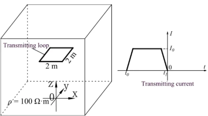
method of transmitting loop in arbitrary direction used in this paper. The result is shown in Fig. 5. The model used is a homogeneous whole-space model with the resistivity is 100·m. Coincident loops with size of 2 m × 2 m are used for transmitting and receiving and the transmitting current wave is a trapezoidal wave. The mesh used in modeling is a non-uniform mesh. The grid near the transmitting loop is 1 m, and the grid becomes larger further from the trans-mitting loop. The grid range is −1480 ∼ 1480 m. The time step in the rising and falling edges is 10−9s, and gradually increases at other times. The convolutional perfectly matched layer (CPML) boundary conditions [24], [25] are used for the modeling. The curves of induced electromotive force generated by transmission along x direction, z direction and arbitrary direction (θ = 50◦, ϕ = 30◦) coincides well with the analytical solution, indicating that the loading method of transmitting loop used in this paper has high accuracy. This method not only realizes loading the transmitting loop of arbitrary direction in the FDTD method, but also avoids re-generating the grid when changing the transmitting direction.
III. DIFFUSION OF WHOLE-SPACE TRANSIENT ELECTROMAGNETIC FIELD CREATED BY THE UNDERGROUND MAGNETIC SOURCE
A. DIFFUSION OF TRANSIENT ELECTROMAGNETIC FIELD IN HOMOGENEOUS WHOLE SPACE
Different from the ground half space, the diffusion of under-ground transient electromagnetic field is affected by the whole space. Studying the diffusion process of whole-space transient electromagnetic field is of great significance for understanding the coupling process of transient electromag-netic field with the abnormal body under whole-space condi-tion as well as interpreting the underground TEM deteccondi-tion data. Fig. 6 shows a homogeneous whole-space model with a resistivity of 100·m. A 2 m × 2 m transmitting loop is located at the origin of coordinates and its normal is parallel to the z-axis. The transmitting current is a trapezoidal wave with both rising and falling time being 1µs.
FIGURE 6. Diagram of homogeneous whole-space model.
FIGURE 7. Contours of magnetic field intensity after current interruption in homogeneous whole space. (a) t = 0.02 ms. (b) t = 0.04 ms. (c) t = 0.08 ms. (d) t = 0.16 ms.
The 3-D FDTD method is applied to the forward modeling for the model. Fig. 7 shows the contours (in A/m) of magnetic field intensity after current interruption. The contours shown in Fig. 7 is on the vertical plane passing through the center of the loop (xoz plane). The origin of coordinates in the graphs indicates the central position of the transmitting loop. On xoz plane, the component of magnetic field in y direction is 0. The magnetic field is made up of components in x and y directions only. In actual detection, the component along normal of transmitting loop is generally observed. Therefore, the magnetic field intensity in Fig. 7 is the normal component of the transmitting loop, that is, the Z component. In the initial stage, magnetic field diffuses only to the vicinity of transmitting loop; but the scope of its diffusion gradually extends over the time. On the whole, the max intensity of the magnetic field is always located at the center of the transmitting loop. In other words, the magnetic field intensity
FIGURE 8. Contours of induced electric field after current interruption in homogeneous whole space. (a) t = 0.02 ms. (b) t = 0.04 ms.
(c) t = 0.08 ms. (d) t = 0.16 ms.
at the center of transmitting loop is always higher than that at other locations.
Fig. 8 shows the contours (in V/m) of induced electric field after current interruption. The contours shown in Fig. 8 is on the vertical plane passing through the center of the loop (xoz plane). On the xoz plane, electric field intensity contains only y-direction component, which means the electric field is perpendicular to xoz plane. Therefore, the electric field intensity in Fig. 8 is the y-direction component. In the early period, the induced electric field is mainly located around the transmitting loop with its max value is the same as the depth of the transmitting loop. As time goes by, the induced electric field keeps diffusing to the surrounding area and its max value extends towards both sides of x-axis.
The half-space transient electric field follows the ‘‘smoke ring effect’’ in distribution [26], that is, the contour ring of the electric field moves downward and its radius keeps expanding. Compared with the half space, the electric field in whole space has both its positive and negative maximum contour rings located on the plane of transmitting loop. That is, the radius of the contour rings keeps expanding but never moves vertically along the axis of transmitting loop.
B. DIFFUSION OF WHOLE-SPACE TRANSIENT ELECTROMAGNETIC FIELD UNDER THE INFLUENCE OF A LOW-RESISTANCE BODY
TEM is mostly applied to the detection of low-resistance bodies. Fig. 9 shows a homogeneous whole-space model with a 3-D low-resistance body. The resistivity of whole-space
medium is 100 ·m, and a 2 m × 2 m transmitting loop
FIGURE 9. A homogeneous whole-space model with a 3-D low-resistance body.
FIGURE 10. Contours of magnetic field under the effect of low-resistance body. (a) t = 2µs. (b) t = 8 µs. (c) t = 31 µs. (d) t = 103 µs.
is situated at the origin of coordinates with its normal in the vertical direction (z-axis). The transmitting current is a trapezoidal wave with both rising and falling time being 1µs. The resistivity of the low-resistance body is 1·m, and its size is 40 m × 40 m × 40 m. It is located right below the transmitting loop, and the vertical distance between the upper end and the transmitting loop is 40 m.
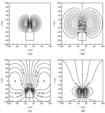
Fig. 10 shows the contours (in A/m) of magnetic field intensity after current interruption, in which the origin of coordinates indicates the central position of the transmitting loop. The contours shown in Fig. 10 is on the vertical plane passing through the center of the loop (xoz plane). As shown in Fig. 10, at initial moments, the maximum value of mag-netic field remains close to the transmitting loop. At this time, the magnetic field diffuses only to the vicinity of the
FIGURE 11. Contours of electric field affected by low-resistance body. (a) t = 2µs. (b) t = 8 µs. (c) t = 31 µs. (d) t = 103 µs.
transmitting loop and its distribution is only affected by the resistivity of the medium around transmitting loop. However, as time goes by, the diffusion scope of transient magnetic field is slowly extended and its distribution is prone to be affected by the low-resistance body. At t = 31µs (Fig. 10c), the maximum contour of the magnetic field moves already into the low-resistance body and its contour distribution is significantly affected by the abnormal body. As time further goes by, the low-resistance body constitutes completely the center of the contour of magnetic field at t = 103µs. The low-resistance body at this time turns to be a ‘‘secondary source’’ that radiates electromagnetic field into the space.
Fig. 11 shows the contours (in V/m) of induced electric field in y direction after current interruption. The contours shown in Fig. 11 is on the vertical plane passing through the center of the loop (xoz plane). As shown in this figure, at initial moments, the induced electric field is mainly dis-tributed around the transmitting loop and only affected by the resistivity of the medium around transmitting loop. The positive and negative maximum values of the induced field are located on the left and right sides of the loop, while the maximum depth coincides with the depth of transmitting loop. Over the time, the induced electric field diffuses grad-ually to the surrounding area and reaches the low-resistance body. After that, its distribution becomes affected by the
low-resistance body. At t = 31 µs, the maximum contour of
the induced electric field is already located within the low-resistance body, and the contours remains densely located in the upper part of the body under its effect. As time fur-ther goes by, the low-resistance body becomes a ‘‘secondary source’’ that radiates electromagnetic field into the space
at t = 103µs. By this time, the observed signals mainly reflect the attenuation of transient electromagnetic field under the influence of the low-resistance body. The diffusion of whole-space transient electromagnetic field under the influence of low-resistance body indicates that the distribution of transient magnetic and electric fields can significantly be influenced by the low-resistance body. Thus, the low-resistance body can be detected by observing the changes in transient electromag-netic field.
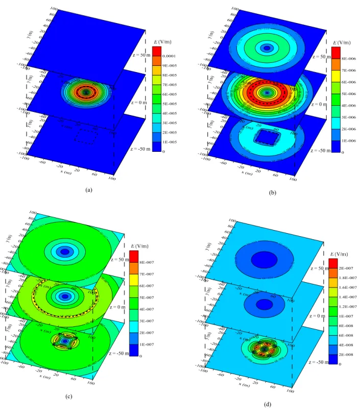
The field distributions shown in the figures above are on the vertical plane passing through the center of the loop. Fig. 12 shows the distribution of transient electric field (in V/m) on the horizontal planes with z being 50 m, 0 m and −50 m, respectively. As shown in Fig. 12, in the initial stage, the induced current is mainly located around the plane with z being 0 and its maximum radius is 20 m, while no induced current is generated yet at this time on the planes with z being 50 m and −50 m. As time goes by, the induced current diffuses upward and downward. At t = 8µs, the electric fields on z = −50 m plane and z = 50 m plane differ a lot from each other due to the effect of the low-resistance body. The maximum radius of the current ring at this moment is 38 m.
At t = 31 µs, the maximum radius of induced current
increases to be 68 m, and the current on z = −50 m plane is mainly concentrated in the low-resistance body. As time further goes by with t reaching 103µs, the maximum induced current is already within the low-resistance body. By this time, the distribution of induced electric field is mainly affected by low-resistance body.
C. COMPARISON OF WHOLE-SPACE TEM RESPONSES WITH DIFFERENT EXCITATION DIRECTIONS
The transmitting loop of ground TEM is usually laid out on the surface, and it can be moved around as per the location of target. By contrast, the transmitting loop of underground TEM is limited to the space of roadway so that it can only move within the roadway without being located as needed. To detect the target ahead of the roadway, it is feasible to achieve spatial orientation merely by changing the direction of the transmitting loop. Fig. 13 shows the model of different excitation directions. A low-resistance body is located ahead of the roadway in homogeneous whole-space media, and the excitation directions in the figure represent the normal direc-tion of transmitting loop. The resistivity of the homogeneous whole space is 100 ·m, a low-resistance body with size of 50 m × 50 m × 50 m is located 40 m ahead of the roadway. The transmitting loop is located at the underground roadway head, and the angles between the normal direction and the axis of the roadway are 0◦, 30◦, 60◦and 90◦, respec-tively. The device adopted is the coincident loop, and the receiving loop rotates synchronously with the transmitting loop.
The 3-D FDTD method is applied to the numerical simulation of the TEM responses with different exci-tation directions. The induced potential is converted to apparent resistivity according to the calculation method of
FIGURE 12. Electric field distribution on different horizontal planes under the effect of low-resistance body. (a) t = 2µs. (b) t = 8 µs. (c) t = 31µs. (d) t = 103 µs.
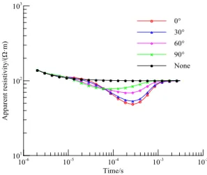
whole-space apparent resistivity [27], so as to intuitively reflect the electrical characteristics around the roadway head. Fig. 14 shows the time-varying curves of apparent resistivity under different excitation directions, in which the excitation direction means the angle between normal of transmitting loop and roadway axis. As shown in the figure, at the ini-tial moments, the response curves of different excitation
directions coincide with that with no low-resistance body, indicating the secondary field information received during this period of time is not influenced by the low-resistance body but rather by the resistivity of the stratum around the roadway head. As time moves on, the information is gradually affected by the low-resistance body and the apparent resistiv-ity curves under the influence of low-resistance body begins
FIGURE 13. Model of different excitation directions.
FIGURE 14. Apparent resistivity curves of whole-space TEM response under different excitation directions.
to be separated from the apparent resistivity curve without low-resistance body.
The apparent resistivity curves for all excitation directions are lower than that without low-resistance body, which indi-cates that the low-resistance response is manifested in all the excitation directions. Comparing the apparent resistivity response curves of different excitation directions, the smaller the angle between excitation direction and the roadway axis is, the lower the apparent resistivity curves is and the more obvious the low-resistance response is. When the excitation direction is consistent with the bearing of the low-resistance body, the coupling between the transient electromagnetic field and the resistance body is best, and the low-resistance response is the most obvious. The above results show that although all the excitation directions will cause low-resistance response, the bearing of target can be distin-guished by comparing the responses of different excitation directions.
IV. WHOLE-SPACE TEM RESPONSES OF WATER-RICH AREA GENERATED BY MULTI-DIRECTIONAL
MAGNETIC SOURCE
The diffusion pattern of the whole-space transient electro-magnetic field is studied above, and the results indicate that the low-resistance body can be detected by observing the
FIGURE 15. Model of water-bearing fault in underground coal mine.
change of transient electromagnetic field. The comparison of whole-space TEM responses with different excitation direc-tions reveals that the position of the low-resistance body can be located by comparing the response information of different excitation directions. In Fig. 15, a whole-space geoelectric model for the underground water-rich area is established on the basis of the actual coal measure strata information. A water-bearing fault exists 50 m ahead of the roadway. The fault strike is perpendicular to the tunneling direction, and the throw of the fault is 20 m. The water-bearing zone of the fault extends by 50 m along the fault strike, and its resistivity is set as 1·m. In the model, roof resistivity and floor resistivity are set as 200 and 400·m, respectively. Resistivity of coal seam is set as 800·m, and the thickness of the coal seam is set as 10 m. Multi-directional excitation can be carried out in the roadway head according to the TEM responses of differ-ent excitation directions. The abnormal body in front of the roadway head can be detected and located by comparing multi-directional responses. In order to accurately detect the water-bearing fault, multi-directional sector detection tech-nology (Fig. 15) is designed, and the direction in the figure is the normal of the transmitting loop. Furthermore, survey points are arranged every 15◦from the left to right to achieve a sector scanning.
Forward simulation of TEM responses of each excitation direction is performed. The resulting induced potential is converted to apparent resistivity [27]. The time is converted to depth through the time-depth conversion method [28]. According to the comparison results of different excitation directions, the abnormal response generated by the target located in the excitation direction is the most significant one. Based on this, the apparent resistivity results of all direc-tions can be converted into 2-D data volumes as per excitation direction. The result is a sector diagram, as shown in Fig. 16. In this figure, horizontal coordinates represent the distance perpendicular to the roadway axis (left side by negative ones and right side by positive ones), whereas vertical coordinates represent the distance along the tunneling direction of the
FIGURE 16. Whole-space TEM responses generated by multi-directional magnetic source.
roadway. The origin of coordinates corresponds to the roadway head. According to the figure, the apparent resis-tivity isoline around the roadway head (within 30 m of the roadway head) is approximately circular distribution with the roadway head as the center, indicating the induction signals of all the excitation directions change almost in the same pattern within the time range corresponding to this depth range. During this period of time, the induction signals are mainly influenced by strata. Within the range of 30 m near the roadway head, as circular radius increases, the apparent resistivity values gradually decrease. This can be accounted for by the fact that the roof and floor of coal seam in the coal-bearing strata are low-resistance relative to the coal seam. In the early stage, the apparent resistivity is mainly affected by the coal seam. With the diffusion of electromagnetic field, the received induction signals gradually enhanced by the influence of coal seam roof and floor, which causes the apparent resistivity to decrease with increasing depth.
There is a low-resistivity anomaly area at a distance of 45 - 60 m ahead of the roadway. The position of the low-resistivity anomaly area is basically consistent with the location of the fault, which is the low-resistance response generated by the water-bearing fault. According to the comparison results of different excitation directions, when the excitation direction is consistent with the bearing of the low-resistance body, the low-low-resistance response is the most obvi-ous. As a result, the low-resistance abnormal response excited at 90◦in Fig. 15 should be the most significant one, which is consistent with the location of the low-resistivity anomaly area in Fig. 16. The result suggests the low-resistance abnormal area in apparent resistivity resulting from the multi-directional sector detection technology can reflect the location of the low-resistance body. The multi-directional detection method provides a solution to the positioning of target ahead of the roadway, for it can not only detect such target but also determine its location.
V. PRACTICAL APPLICATION
The whole-space TEM responses generated by the magnetic source are studied in previous sections, the TEM responses
FIGURE 17. Cross-section of apparent resistivity of underground TEM detection.
of water-rich areas generated by multi-directional magnetic source is numerically modeled based on the actual geological model of coal mine. The results can shed some light on the detection practice. We conducted an experiment with underground TEM in a coal mine in Anhui, China. The coal-bearing strata of the mine is Carboniferous-Permian System of Shanxi Formation, Lower Shihezi Formation and Upper Shihezi Formation. There are about 10 - 30 coal seams, among which 14 remains exploitable. The experiment is adopted in the Lower Shihezi Formation with the roof being made of siltstone and mudstone and floor made of mudstone. The principal water source for the mine is from the fourth water-bearing bed in unconsolidated formation of Cenozoic erathem. To find out the water content in the rock stratum ahead of the tunneling roadway, underground TEM is employed in the roadway head. The working parameters are as follows. The transmitting voltage is 24 V, transmitting cur-rent is 4.5 A, transmitting frequency is 2.5 Hz (corresponding time windows are 0.0015 - 94.2 ms), ramping time is 1.1 ms. The detection device is made of 2 m × 2 m small multiturn loops and survey points are arranged as the multi-directional sector detection specified in Fig. 15.
During data processing, the measured voltage is converted to apparent resistivity [27]. Due to the influence of multi-turn small loop and metal mesh in roadway, the apparent resis-tivity is low on the whole, which will cause errors in depth conversion. Therefore, after the time-depth conversion [28], the depth is corrected based on the comparison of actual detection results and verification results of the past 20 years. Fig. 17 is the sector apparent resistivity contour diagrams of underground TEM. Here, horizontal coordinates represent the distance perpendicular to the roadway axis (left side by neg-ative ones and right side by positive ones), whereas vertical coordinates represent the distance along the tunneling direc-tion of the roadway. The origin of coordinates corresponds to the roadway head. In Fig. 17, there is a low-resistance area of apparent resistivity contours at front left of the roadway. The apparent resistivity in this area is significantly lower than that in other areas, Which is the low-resistance reflection of the water-rich area. In accordance with the numerical
simulation results, the bearing of water-rich area is consistent with the excitation direction of most obvious low-resistance response, that is, the location of the low-resistance area shown in Fig. 17. This result is subsequently verified by drilling, indicating underground TEM can accurately detect and posi-tion the water-rich areas.
VI. CONCLUSIONS
The diffusion of whole-space transient electromagnetic field and the whole-space TEM response generated by multi-directional magnetic source are numerically modeled by using the 3-D FDTD method. The results are applied to the practical underground detection. The conclusions are as follows:
(1) The diffusion of whole-space transient electromagnetic field is different from half space. The radius of the electric field’s contour ring in the whole space keeps increasing with-out moving upward or downward, which does not conform to the ‘‘smoke ring effect’’ of half-space transient electromag-netic field.
(2) The low-resistance body can significantly affect the diffusion of transient electromagnetic field. and the low-resistance response is manifested in all the excitation direc-tions. When the excitation direction is consistent with the bearing of the low-resistance body, the coupling between the transient electromagnetic field and the low-resistance body is best, and the low-resistance response is the most obvious. The bearing of target can be distinguished by comparing the responses of different excitation directions.
(3) The multi-directional detection method provides a solu-tion to the posisolu-tioning of target ahead of the roadway, and it can not only detect such target but also determine its location. Both numerical simulation and practical underground appli-cation have proven the capacity of the method in accurately reflecting the location of water-rich areas.
DECLARATION OF INTEREST
The authors declare that there is no conflict of interests regarding the publication of this paper.
REFERENCES
[1] Q. Wu, Y. Liu, L. Luo, S. Liu, W. Sun, and Y. Zeng, ‘‘Quantitative evaluation and prediction of water inrush vulnerability from aquifers over-lying coal seams in Donghuantuo Coal Mine, China,’’ Environ. Earth Sci., vol. 74, no. 2, pp. 1429–1437, 2015.
[2] Q. Liu, Y. Sun, Z. Xu, and G. Xu, ‘‘Application of the comprehensive identification model in analyzing the source of water inrush,’’ Arabian J.
Geosci., vol. 11, no. 9, p. 189, 2018.
[3] A. Legchenko, M. Ezersky, C. Camerlynck, A. Al-Zoubi, K. Chalikakis, and J.-F. Girard, ‘‘Locating water-filled karst caverns and estimating their volume using magnetic resonance soundings,’’ Geophysics, vol. 73, no. 5, pp. G51–G61, 2008.
[4] B. Su, R. Malekian, J. Yu, X. Feng, and Z. Liu, ‘‘Electrical anisotropic response of water conducted fractured zone in the mining goaf,’’ IEEE
Access, vol. 4, pp. 6216–6224, 2016.
[5] W. Chen et al., ‘‘A comparison of loop time-domain electromagnetic and short-offset transient electromagnetic methods for mapping water-enriched zones—A case history in Shaanxi, China,’’ Geophysics, vol. 82, no. 6, pp. B201–B208, 2017.
[6] B.-Y. Su and J.-H. Yue, ‘‘Research of the electrical anisotropic character-istics of water-conducting fractured zones in coal seams,’’ Appl. Geophys., vol. 14, no. 2, pp. 216–224, 2017.
[7] G. Xue, D. Hou, and W. Qiu, ‘‘Identification of double-layered water-filled zones using TEM: A case study in China,’’ J. Environ. Eng. Geophys., vol. 23, no. 3, pp. 297–304, 2018.
[8] J. C. Yu, Z. X. Liu, S.-C. Liu, and J.-Y. Tang, ‘‘Theoretical analysis of mine transient electromagnetic method and its application in detecting water burst structures in deep coal stope,’’ J. China Coal Soc., vol. 32, no. 8, pp. 818–821, 2007.
[9] J. Cheng, F. Li, S. Peng, X. Sun, J. Zheng, and J. Jia, ‘‘Joint inversion of TEM and DC in roadway advanced detection based on particle swarm optimization,’’ J. Appl. Geophys., vol. 123, pp. 30–35, Dec. 2015. [10] M. Y. Khan, G. Q. Xue, W. Y. Chen, and H. S. Zhong, ‘‘Analysis of
long-offset transient electromagnetic (LOTEM) data in time, frequency, and pseudo-seismic domain,’’ J. Environ. Eng. Geophys., vol. 23, no. 1, pp. 15–32, 2018.
[11] J. Chang, J. Yu, and B. Su, ‘‘Numerical simulation and application of mine TEM detection in a hidden water-bearing coal mine collapse column,’’
J. Environ. Eng. Geophys., vol. 22, no. 3, pp. 223–234, 2017.
[12] Y. Li, T. Qi, B. Lei, Z. Li, and W. Qian, ‘‘An iterative inversion method using transient electromagnetic data to predict water-filled caves during the excavation of a tunnel,’’ Geophysics, vol. 84, no. 2, pp. E89–E103, 2019.
[13] A. Swidinsky and M. Nabighian, ‘‘Transient electromagnetic fields of a buried horizontal magnetic dipole,’’ Geophysics, vol. 81, no. 6, pp. E481–E491, 2016.
[14] G. Xue, W. Chen, and S. Yan, ‘‘Research study on the short offset time-domain electromagnetic method for deep exploration,’’ J. Appl. Geophys., vol. 155, pp. 131–137, Aug. 2018.
[15] A. V. Christiansen and N. B. Christensen, ‘‘A quantitative appraisal of air-borne and ground-based transient electromagnetic (TEM) measurements in Denmark,’’ Geophysics, vol. 68, no. 2, pp. 523–534, 2003.
[16] A. Viezzoli, J. P. Cull, and D. Massie, ‘‘Mapping fly-ash water pond leakage with TEM and IP data at Loy Yang coal-mine (Australia),’’ Near
Surf. Geophys., vol. 4, no. 5, pp. 305–311, 2006.
[17] G. Q. Xue, Y. J. Yan, and J. L. Cheng, ‘‘Researches on detection of 3-D underground cave based on TEM technique,’’ Environ. Earth Sci., vol. 64, no. 2, pp. 425–430, 2011.
[18] K. Chen, G. Xue, W. Chen, N. Zhou, and H. Li, ‘‘Fine and quantitative evaluations of the water volumes in an aquifer above the coal seam roof, based on TEM,’’ Mine Water Environ., vol. 38, no. 1, pp. 49–59, 2019.
[19] T. Wang and G. W. Hohmann, ‘‘A finite-difference, time-domain solution for three-dimensional electromagnetic modeling,’’ Geophysics, vol. 58, no. 6, pp. 797–809, 1993.
[20] S. Li, H. Sun, X. Lu, and X. Li, ‘‘Three-dimensional modeling of transient electromagnetic responses of water-bearing structures in front of a tunnel face,’’ J. Environ. Eng. Geophys., vol. 19, no. 1, pp. 13–32, 2014. [21] Z. Jiang, S. Liu, and R. Malekian, ‘‘Analysis of a whole-space transient
electromagnetic field in 2.5-dimensional FDTD geoelectric modeling,’’
IEEE Access, vol. 5, pp. 18707–18714, Sep. 2017.
[22] J. Yu, R. Malekian, J. Chang, and B. Su, ‘‘Modeling of whole-space transient electromagnetic responses based on FDTD and its application in the mining industry,’’ IEEE Trans. Ind. Informat., vol. 13, no. 6, pp. 2974–2982, Dec. 2017.
[23] K. Yee, ‘‘Numerical solution of initial boundary value problems involving Maxwell’s equations in isotropic media,’’ IEEE Trans. Antennas Propag., vol. AP-14, no. 3, pp. 302–307, May 1966.
[24] M. Kuzuoglu and R. Mittra, ‘‘Frequency dependence of the constitu-tive parameters of causal perfectly matched anisotropic absorbers,’’ IEEE
Microw. Guided Wave Lett., vol. 6, no. 12, pp. 447–449, Dec. 1996. [25] J. A. Roden and S. D. Gedney, ‘‘Convolutional PML (CPML): An efficient
FDTD implementation of the CFS-PML for arbitrarymedia,’’ Microw. Opt.
Technol. Lett., vol. 27, no. 5, pp. 334–338, 2000.
[26] A. Swidinsky and M. Nabighian, ‘‘On smoke rings produced by a loop buried in a conductive half-space,’’ Geophysics, vol. 80, no. 4, pp. E225–E236, 2015.
[27] J. Chang, B. Su, R. Malekian, and X. Xing, ‘‘Detection of water-filled mining goaf using mining transient electromagnetic method,’’ IEEE Trans.
Ind. Informat., to be published. doi:10.1109/TII.2019.2901856. [28] J.-C. Yu, Y.-Z. Wang, L. Jian, and X.-B. Zeng, ‘‘Time-depth conversion
of transient electromagnetic method used in coal mines,’’ J. China Univ.
JINGCUN YU received the Ph.D. degree in geophysics from the Department of Applied Geo-physics, China University of Mining and Tech-nology, Xuzhou, China, in 2000. He is currently with the China University of Mining and Technol-ogy, Xuzhou, as a Professor. His research interest includes mine geophysics.
JUANJUAN LI received the Ph.D. degree in geo-physics from the China University of Mining and Technology, Xuzhou, China, in 2013, where she is currently with the Department of Geophysics. Her research focuses on geological disasters interpre-tation in coal mine.
REZA MALEKIAN (M’10–SM’17) is currently with the Department of Computer Science and Media Technology, Malmö University, Sweden. His research focuses on advanced sensor technolo-gies. He is also a Chartered Engineer and a Profes-sional Member of the British Computer Society. He is an Associate Editor of the IEEE INTERNET OFTHINGSJOURNALand the IEEE TRANSACTIONS ON
INTELLIGENTTRANSPORTATIONSYSTEMS.
BENYU SU received the Ph.D. degree in geo-physics from the Faculty of Earth Resource of Engineering Department, Kyushu University, Fukuoka, Japan, in 2012. He is currently an Asso-ciate Professor with the China University of Min-ing and Technology, Xuzhou, China. His current research interests include mine and environment geophysics.