Abstract
During the last century, furniture design has developed to become more finan-cially accessible. Most furniture during the past decades are designed to facili-tate the storage and transport of the product to minimise costs for the company. The company can let the customer assemble the furniture themselves at home to reduce the price even more. For customers’ to be satisfied, the assembly of the furniture needs to go quickly and easily. The objective of this thesis is to improve today’s assembling process of frame-based furniture with focus on series of FAMILY A at IKEA. To gather information about what problems a customer may encounter today when assembling the furniture different methods are used such as consulting experts and internal benchmarking. A requirement and characteristics matrix is made as a guideline for what the new concepts should fulfill. To get ideas on new concepts that can improve the design, meth-ods such as external benchmarking, patent search and brainstorming are used. The result is 19 different concepts that will improve several different problems. By consulting experts from IKEA in a focus group, one of the concepts named the Indented frame is chosen for further development. A 3-dimensional model is made to visualise the new concept and the Indented frame is adapted to existing components for wall hanging for the previous model of FAMILY A. Based on the 3-dimensional model, drawings are produced for the first prototypes. The prototypes assembly time are measured and a load test is carried out to mea-sure the durability for the new concept. The result is that the new design has a decreased assembly time and the load test shows that there is no significant difference in durability. After the tests the new concept is evaluated compared to the old design in view of form, function, quality, sustainability and low price. The conclusion is that the new concept would improve the furniture and the customers’ experience when assembling.
Sammanfattning
Under det senaste ˚arhundrandet har m¨obeldesign utvecklats och designats f¨or att bli mer ekonomiskt tillg¨anligt. Majoriteten av m¨oblerna under de senaste ˚artiondet ¨ar designade f¨or att underl¨atta f¨ovaring och transport f¨or att minimera kostnaden f¨or f¨oretaget. F¨oretaget kan l˚ata kunden montera det sj¨alva i hemmet f¨or att reducera priset ytterligare. F¨or att kunderna ska bli n¨ojda beh¨ovs det en snabb och intuitiv monteringsl¨osning. Detta projektets syfte ¨ar att f¨orb¨attra monteringen f¨or rambaserade m¨obler med fokus p˚a FAMILJ A fr˚an IKEA. F¨or insamling av information g¨allande de problem som kan komma upp n¨ar kun-den monterar ihop m¨obler anv¨ands olika metoder s˚a som intern benchmarking och konsultering av experter. En behovs- och egenskaps matris uppr¨attas som hj¨alp och riktlije f¨or vad de nya koncepten b¨or upfylla. F¨or att generera id´eer f¨or nya koncept som kan f¨orb¨attra designen, anv¨ands metoder s˚a som extern benchmarking, patents¨okning och brainstorming. 19 olika koncept och id´eer som f¨orb¨attrar och l¨oser olika problem togs fram. Genom att konsultera ex-perter p˚a IKEA i en fokusgrupp v¨aljs ett koncept ut som kallas f¨or ”Indented frame”. Konceptet vidareutvecklas och en 3-dimensionel modell genereras f¨or att visualisera det nya konceptet. Indented frame modifieras och anpassas efter dagens inf¨astningsanordning. Baserat p˚a den 3-dimensionella modellen skapas ritningar f¨or tillverkning av prototyper. Prototypens monteringstid m¨ats och ett belastningstest utf¨orst f¨or att m¨ata h˚allfastheten. Resultatet ¨ar att den nya designen har en enklare monteringsprocess, snabbare monteringstid och be-lastningstestet visar ingen st¨orre skillnad i h˚allfasthet. Efter belastningstestet utv¨arderas det nya konceptet med dagens produkt som referens. Detta g¨ors utifr˚an form, funktion, kvalit´e, h˚allbarhet och l˚agt pris. Slutsatsen ¨ar att det nya konceptet ¨ar en f¨orb¨attrad design.
Acknowledgement
We would like to acknowledge H˚akan Wernersson at Malm¨o university that has contributed and supported us through the project. We would also like to thank and pay tribute to all IKEA employees that contributed with their expert knowledge and guidance. Highlight the eminent wedge dowel team at IKEA Components AB in ¨Almhult, especially our mentor Muthumariappan Sankaran.
Contents
1 Introduction 1
1.1 Defining the problem . . . 1
1.2 Scope and objective . . . 4
1.3 Delimitations . . . 4
2 Design methodology 5 2.1 Benchmarking . . . 5
2.2 Consulting experts . . . 6
2.3 Requirement and characteristics matrix . . . 6
2.4 Patent search . . . 7 2.5 Brainstorming . . . 8 2.6 Selection of concept . . . 9 2.7 Development of concept . . . 10 2.7.1 Visualisation . . . 10 2.7.2 Calculations . . . 10 2.7.3 Testing . . . 11 2.8 Concept evaluation . . . 12 3 Result 13 3.1 Benchmarking . . . 13 3.2 Consulting experts . . . 15
3.3 Requirement and characteristics matrix . . . 15
3.4 Patent search . . . 16
3.5 Brainstorming . . . 17
3.5.1 Generated concepts for FAMILY A . . . 17
3.5.2 Generated concepts for FAMILY B . . . 23
3.5.3 Generated concepts for back panel solution . . . 25
3.6 Selection of concept . . . 29 3.7 Development of concept . . . 30 3.7.1 3-dimensional model . . . 31 3.7.2 Prototype . . . 34 3.7.3 Calculations . . . 35 3.7.4 Testing . . . 39 3.8 Concept evaluation . . . 42 4 Discussion 44 5 Conclusions 47 References 48 Appendix A1
B Comments about the 19 different concepts B1 C Assembly instruction of previous and modified design C1 D Result of evaluation of concept D1
1. INTRODUCTION
1
Introduction
Furnishing is a natural part of Swedish households today. The furniture has a practical and decorative purpose. It has not always been obvious that everyone should be able to furnish their homes. Earlier in history, it was only the wealthier people in society who could afford well-designed furniture [1]. The last century furniture design has developed to become more financially accessible [2].
The price of a furniture can be reduced by various strategies that deal with the design, such as manufacturing, packaging and choice of materials [3]. Most furniture during the past decades are designed to facilitate the transport of the product to minimise costs. Packaging of furniture in flat packages has led to a more cost effective way to store and ship the furniture [4]. To reduce the price even more, the company can let the customer assemble the furniture themselves at home. This has led to the development and improvement of various mounting solutions for furniture to increase customer satisfaction and sales. Over time, the demand for toolless assembly solutions has become increasingly important as fewer households have access to tools. Another factor influencing the design of the furniture is that the human ability to concentrate is limited [5]. Therefore, there is a market demand for an assembly which is time-effective and easy to assemble without any tools. The assembly should also be intuitive and straight-forward to assemble because numerous people do not follow the instruction’s that follows [6].
1.1
Defining the problem
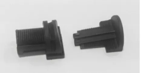
IKEA has developed a solution called wedge dowel in order to help the customer assemble the furniture themselves. The design of the plug in the wedge dowel is shown in figure 1. The solution consists of a dowel of either wood or plastic material. The dowel is pressed down into a milled groove where it wedges into place and fix the parts, as shown in figure 2. This method is similar to the methods that have been used for a long time to join wooden components with woodworking joints [7]. An identified issue with wedge dowel is that it can be difficult to assemble the parts as they need space to be placed in the groove and pushed in place to lock the parts. Another issue is that some parts needs to be assembled in a specific order. This has in particular been observed in the shelf series FAMILY A, which is shown in figure 3 [8]. FAMILY A have four frame panels that has to be assembled in a specific order. The order is the top and side panels first, then the back panel and lastly the bottom panel. This order is important so that the back panel can slide into the deeper groove in the top panel, without being offset. If the back panel is offset the last frame can not be assembled in a correct way because the panel is in the way. When a shelf from FAMILY A is assembled in the wrong way the customer has to disassemble the furniture and start over in order to do it in the correct way. It is difficult to disassemble furniture with wedge dowel because it is not clear which way to push the parts. The customer can become irritated or frustrated if the assembly takes too long or if the product breaks due to pressing the parts in the wrong
1. INTRODUCTION
direction.
IKEA have for a long time been working with what they call Democratic Design. All the products have to follow this design and include these five cor-nerstones in order to be in line with IKEA values [9]. The five corcor-nerstones include:
• Form: Support variety of styles and expressions. Through attention to details the solution should raise appearance of the final outcome.
• Function: Increase functionality and improve ease of use of final product. Support built-in functionality beyond customers’ expectations and have an inventive step.
• Quality: Risk of producing defect components and products should de-crease. Improved durability and an enjoyable assembly experience with decreased assembly time.
• Sustainability: The solution should use less material, contribute to im-prove the transport efficiency. It should also imim-prove separability and recyclability.
• Low price: The solution should be more affordable and add high value for money. Contribute to lowering cost and designed to avoid supply limitations. It should also be scaleable to produce.
1. INTRODUCTION
Figure 2: Example of how to assemble a furniture with wedge dowel.
Figure 3: One of the smallest shelf in the series FAMILY A from IKEA. Size 35x35x35.
1. INTRODUCTION
1.2
Scope and objective
The design of frame-based furniture with wedge dowel is being evaluated and improved in order to decrease the assembly time and help the customer with an intuitive solution. This is achieved by generating a new or improved concept along with a prototype. The new concept will be assembled without any tools according to IKEA requisites. However, it is not a requirement that the dis-assemble should be toolless. According to IKEA, the assembly solution should preferably be hidden, otherwise well designed and integrated in the product. The concept should also comply with IKEA Democratic Design guide lines. Fi-nal concept should be in the same price range as similar products from IKEA. The solution should be easy to assemble with as few loose components as pos-sible. In order to recycle the product, it should be able to be dissembled.
1.3
Delimitations
The benchmarking of the assortment within IKEA is focused on FAMILY A, FAMILY B, FAMILY C and FAMILY D. Only FAMILY A and FAMILY B is made with wedge dowel but FAMILY C and D is being evaluated regards to the design and their assembly process. The project is delimited based on requirements given by IKEA. These delimitation’s are made to not require any major change in today’s manufacturing process. The following delimitation’s are:
• IKEA storage platform: frame based geometry.
• Board material: Particle board and Board on Stile (BoS). • Board thickness: 18-22mm.
• Back panel position flush and 16mm indented.
• Back panel material: High Density Fiberboard (HDF), thickness: 2.5mm. • Drawings made during the project will not be included in the project
2. DESIGN METHODOLOGY
2
Design methodology
Generating concepts or ideation of concepts is a creative process of generating or developing new ideas. It is an essential part of a design process and in product development. A generated concept can be a complete solution, a partial solution or just an idea. Ideas can be taken from within a company or outside from other companies. There are different methods to achieve a good outcome with as many concepts and ideas as possible [10]. Different methods that are used is benchmarking, patent search, consulting experts and brainstorming. However, there are other options such as 6-3-5 method, mind-map, brainwalk etc. preferably for a project group with more people than two [11]. When new concepts are generated a selection of concept can be made for example with the help from experts or an elimination matrix [3]. Experts from IKEA are available during the project, therefore they help out with the selection of the final concept. The selected concept gets further developed, tested and evaluated.
2.1
Benchmarking
Benchmarking is a common initial step in product developing. It involves com-paring different business and their solutions. The comparisons could be price, quality, design and time. Benchmarking is a powerful method to find desired and suitable solutions. When using this method, information about a compa-nies competition is explored and it is a good way to learn from them. There is several benchmarking strategies such as:
• Internal benchmarking: Within the company itself, comparing differ-ent teams or departmdiffer-ents. This is good to do in order to find people with knowledge they are willing to share with other employees. This method is mainly for larger companies.
• External benchmarking: Benchmarking of competitors, this method is more difficult since other companies do not share their knowledge. How-ever, it is a good approach to research the companies on for example internet.
• Functional benchmarking: Companies in the same field but not a com-petitor. This is a good approach for improving functional areas, not just separate processes.
• Generic benchmarking: Companies in other fields. This approach is better when the process itself is of greater importance and not the detailed knowledge of a companies products. [12]
Different solutions that are available on the market are explored in order to get an overview of what already exists. If a product from the market has a solution that would solve the problem and is not protected by a patent, it can be applied as a solution.
2. DESIGN METHODOLOGY
Furniture from four different product families are acquired and assembled with the purpose of getting a better understanding of the problem. Assembly of shelf from FAMILY A, FAMILY B, FAMILY C and FAMILY D is being made so that new ideas can be generated. The furniture are assembled meticulous so that every component is looked at. For every step in the assembly pictures is being taken so that if needed, it is possible to go back and look at the different stages in the assembly. When assembling the furniture, the time for finishing the assembly is measured so that it is possible to see how long it takes and then compare it with the amount of loose fittings. The shelf from FAMILY A is also assembled in the wrong order to measure the time for that scenario.
By researching products and concepts on the internet, through literature and scientifically publications, suitable solutions can be devised and evaluated. In order to obtain necessary information about current solutions in today’s market, IKEA competitors are also benchmarked. Other prominent solutions are explored through the internet and by suggestions from IKEA employees.
2.2
Consulting experts
By interviewing and/or consulting an expert within the specific field, knowledge can be obtained in an easier way, especially if the expert is available through the company [3]. Experts are being used with the purpose of gathering information and research throughout the project. Outside counseling can also be made outside of the company for example experts from the university and from other companies.
With the help of employees at IKEA and lectures at Malm¨o University fur-ther ideas are explored and evaluated. Experts at IKEA are consulted regarding issues and questions about production, customer requirements, suppliers and evaluation of new designs. All these areas needs to be understood in order to make a design that is possible to advance. The less that the production has to adapt the better, that is why it would be a good solution if the concept can adapt to the current production or have minimum changes. Experts within IKEA are consulted throughout the project, from research to evaluation of the new concept.
Consulting experts is an easy way of getting a thorough understanding of the problem. It is particularly helpful to consult experts within issues that are specific for the company and where there is limited of information available. This method is used for various tasks especially from experts at IKEA so that everything is done accordingly to IKEA standards.
2.3
Requirement and characteristics matrix
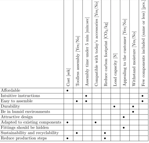
The problems revealed during the research (using benchmarking and consult-ing experts) are compiled into requirements as a guideline for generatconsult-ing new concepts. The criteria that are initially given in the assignment and that ap-pear during analysis and clarification of the task also contributes to this list of requirements. To meet the requirements the new concept needs to have certain
2. DESIGN METHODOLOGY
characteristics. The requirements often satisfy subjective expressions that give a feeling for a customers’ interests. At the same time, the requirements do not provide any specific guidance on how the new concept should be developed. Therefore, specifications are set that specify what has to be achieved in order to satisfy the requirements. A specification has measurable, objective properties with a unit and a value. The value can be expressed in different forms such as a single measurement number, an interval or by a difference. A difference may be yes or no in response to whether the requirement is met.
In a requirement and characteristics matrix, the relationship between the requirement and the characteristics is shown where the rows in the matrix cor-respond to the needs and columns to the properties. A point in a cell in the matrix means that the requirement can be measured with the corresponding property. The measurement units are also included in the matrix. The mea-surement units are usually indicated in SI units such as grams, meters and seconds. [3]
The matrix is made as a guideline for the project and what the generated concepts should achieve. This method is used to ensure that the given re-quirements are fulfilled and that the final concept will achieve the scope of this project. It is a good approach to help highlight the concepts attributes and reassuring that all generated concepts are relevant.
2.4
Patent search
Researching patents is another way of finding existing products with a suitable solution and can be done by searching the Swedish patent and registration website. Patents include technical information and drawings which explains the function. Commonly an invention that gets a patent is protected by the patent law for 20 years commencing from the day of the petition. The solutions which are not protected by law can be used freely in other designs and by other companies. However, different laws in different countries meaning that some patents can be used internationally [3]. The searching for patents is being made by using key-words and is being done on the Swedish patent and registration website [13].
The swedish patent registrations library is used to find adequate inventions or solutions to help generate new ideas. It is also used to look at and do fur-ther research on solutions found from ofur-ther methods such as benchmarking. By searching for keyword seen in table 1 patents are found, which helps generate new ideas that are adequate for the project. When a patent is found all the doc-umentation is inspected so that any helpful information can be found, drawings, technical specification etc.
2. DESIGN METHODOLOGY
Table 1: Keywords that are search for at the Swedish patent registrations web-site in order to find patents.
Keywords Frame-based furniture
Furniture Wooden furniture
Shelf
IKEA frame based furniture IKEA
Wooden shelf Wedge dowel Click function Furniture click function
Furniture with dowel V¨alinge innovation
Patent searching can be time consuming but it is a encyclopedia for inven-tions and soluinven-tions. It is a good method to explore soluinven-tions and find new ideas. Possibility to read and visulise the inventions and solutions can help form new ideas for other or similar solutions.
2.5
Brainstorming
When the problem, objective and scope is known the process of brainstorming can be used. Brainstorming is a good method for generating different creative solutions to a problem and how to solve it. By spreading ideas and talking freely in a group without criticism, ideas and different approaches can be explored and evaluated [14]. All ideas and thoughts are being noted and compiled, these ideas are later on being evaluated more thorough so that the most credible concepts are being presented. The most important part about brainstorming is that all members can speak freely without interruption and explaining their thoughts. Brainstorming is a common method and is used widely in the concept evaluation processes and product development [15].
The brainstorming session is carried out together, all thoughts and ideas are brought up and considered. In order to get the most out of the session, a freely and open-minded ambience is encouraged. By encouraging an open-minded am-bience a lot of different ideas (both relevant and non-relevant) are conceived. To make the brainstorming session more effective everything is divided in to sections. First of is one specific furniture problem (i.e FAMILY A), then gener-ally about FAMILY A. Once this is done on all the pieces of furniture, a session were all products and problems are being brainstormed is held. An example of this is to combine different product solutions or looking outside of the box, on different pieces of furniture.
2. DESIGN METHODOLOGY
to carry out. It is pertinent for this project because of the essential part it plays when it comes to generate and come up with new ideas. This method does not require any extra material or extensive research, it is done alone or in group.
2.6
Selection of concept
The idea of selecting different concepts is to focus the limited resources (for example time, material) to develop those concepts which has most probability to satisfy the objective in the best way possible. A focus group can be used as a help of selecting the concepts. A focus group is a small but selective group of people with a diverse set of skills or background who give their opinion and discusses some ideas. By presenting ideas for this selective group and encourag-ing a discussion, the ideas can be narrowed down in order to focus on the more prominent ones. A focus group approach is a qualitative method since it also consists of interviews, interviewing experts to get everyone’s opinion. During the presentation of the ideas they can be asked to write down their thoughts on paper, ensuring that everyone get their saying and opinion stated. This method can be used in various fields and markets [15]. A focus group can be carried out in different ways, ensuring that all topics are covered and that the session progress smoothly, dual moderator is used in this case. This type of organising a focus group will contribute to more productive sessions. There will be two in-stead of one moderator to oversee the focus group. One moderator ensures that all topics are covered and the second one focus on making the session progress smoothly [16].
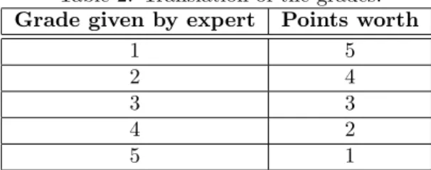
The invited participants in the focus group are experts from different de-partments at IKEA with a diverse set of knowledge, such as design, production and testing. All generated concepts and ideas are presented in the focus group. Everyone is handed a paper with the grade scale one to five where one is the best. All concepts are being discussed so that everyone knows how they work and what the thought behind them is. Continue to next stage were a open discussion is being held, in order for clarification and if the participants have any specific questions or thoughts. When all participants are familiar with the concepts and know the idea behind it, they are asked to fill in the papers handed to them with the grade scale. When the answers is compiled the grades one to five is translated, such that the concept that got a one is worth five points. See table 2 for translation of the grading. This is summarised in a bar chart, where all the concepts final score are compiled and presented.
Table 2: Translation of the grades. Grade given by expert Points worth
1 5
2 4
3 3
4 2
2. DESIGN METHODOLOGY
The concept with the highest score is chosen for further development. When the gathering is concluded, the outcome of the session is evaluated and feedback is given by the participants.
A focus group approach is used because of the access to IKEA experts in different departments. By gathering a selective group of experts and present all the ideas, their opinions can be taken in to account and evaluated during the selection process. These experts are aware of questions regarding production, design and costs. This is helpful in the process of finding the most prominent concept to continue developing.
2.7
Development of concept
The concept chosen for further development is visualised with computer aided design software. Calculations are made to emphasise issues with the associated components. Prototypes are built to test the new assembly time and a strength test is carried out to see its durability.
2.7.1 Visualisation
Sketching freely is a good way to visualise the product or concept for which is being developed. The art of visualising is an intuitive way of describing the products features and its potential for furthering the development. After the sketches being made, a technical drawing can be produced with the help of computer software. These softwares will make it easier to turn the sketches into geometrically scale plans with given tolerances [17]. When the technical drawings are finished the product can be prepared for manufacturing.
Using computer aided design for construction of drawings and 3-dimensional design is an effective tool to model components and/or a whole product. This technology is used in today’s industry whereby realistic models of the final product is made. In addition to drawings and 3-dimensional models, analyses and optimisation can be applied in order to improve and prevent possible issues. This method is time-effective compared to drawing by hand and the margin for error is significantly decreased. The finalised product can easier be prepared for manufacturing which is an advantage as well [18].
In this project, Solidworks will be used as a tool to create models. It is an adequate tool for this project because it is used within IKEA. The new model is adapted to the associated components for the furniture by an assemble. Technical drawings are made from the 3-dimensional model so that prototypes can be produced in the pattern shop at IKEA.
2.7.2 Calculations
Mathematics is a fundamental part of being able to do calculations which has been used before the common era, were it was applied to build infrastruc-ture [19]. Calculations can be used as a method to ensure the quality of a product. The method can also be used in order to predict critical areas where
2. DESIGN METHODOLOGY
the product has the highest probability to fail. Calculations can be made with the help of computer software and/or by hand. Software that is being used to do calculations is Matlab.
Calculations is being made with the help of the numerical computing pro-gramme Matlab. Matlab is a matrix-based language for computational mathe-matics. With the help of Matlab functions and subroutines that has been coded in C or Fortran can be called. This is a good tool to calculate and plot functions. It has several application areas such as machine learning, signal processing and deep learning [20]. By programming given formulas and plotting them a graph can be obtained. The graph is then interpretted and a result is given.
2.7.3 Testing
The selected concept is validated with regards to assembly time and durability by comparing the new concept with the current design.
Assembly test
The assembly time for the new concept is measured during the assembly of the prototype. Assembly test are done to see if the projects objective is achieved. The assembly of both previous model and new concept are made by four different people outside of the project to compare the new concept with the previous model. The persons doing the assembly gets different conditions. Two people gets no instructions, one of them starts with the prototype and the other one starts with the current design. Two of them gets the instructions and one of them starts with the prototype and the other one starts with the current design. The assemblies are monitored and time is clocked. After the activity, the persons are given the opportunity to comment and evaluate the assembly. The results and comments are considered important for evaluation in order to know if the new concept meets the purpose and objective of the project. Therefore, these are included in the evaluation of the concept.
Load test
A load test is done with the purpose of comparing how much load the new design can endure compared with today’s design. Therefore, the load will be applied on the most critical point of the furniture while hanging on a wall, one of the outer corners (to get the largest possible distance between the attachment and the applied force).
IKEA have a test lab where the load test takes place. The test is done in the following way. Three pieces of furniture is mounted on the wall, one is the current design of the model, from the department store and the remaining two are prototypes of the new concept. The setup consist of a machine that puts vertical pressure on the outer corner of the furniture resulting in compressive stress in the material. With the help of a computer and two loading cells, data is collected in a final test report. The applied force is variable and progressively
2. DESIGN METHODOLOGY
increased, proportional to the deflection of the furniture and the wall, until breakage occur.
2.8
Concept evaluation
When it comes to evaluation of the design IKEA have their own Product De-velopment System (PDS) score card for evaluating how good the new concept is compared to the previous one. This method is used with help of experts so that everything is being done the right way and controlled. The final result will then be more plausible and possible to implement. The score card is used to evaluate if the developed concept is better than the previous model. Therefore only these two concepts are compared in the PDS score card. The evaluation is based on the five cornerstones of the Democratic Design within IKEA such as function, form, quality, sustainability and low price. Four questions for each area is asked and scored.
The method that is used to implement the PDS score card is based on the same principle as Pugh concept selection. It is a method that is often used to select the most suitable concept. One concept is chosen to be a reference that the new concepts are being compared with. All the other concepts are being compared with the reference and given a (+) or (-) depending if it is better than the reference. If it is equally good, this will be indicated by a value of 0. The score is compiled and the concept with highest score is considered the winning concept. [3]
A handout is handed to people involved in the project, were they are asked to rank the final concept with regards to specific categories, compared to today’s solution. The score is then compiled and if the concept scores more than one on any of the questions it is improved. The result from the PDS score card is an important document that will be a key argument for why the concept should be further developed or implemented in the production. The scoring is not as in the ordinary Pugh concept selection, it is done according to IKEA standard and the grading scale can be seen in table 3. This method is used so that it is possible to see how much better the new design is compared to the current design.
Table 3: PDS score card evaluation.
Score Meaning
1 The concept ranks worse or similar 2 The concept is slightly better 3 The concept is clearly better 4 The concept is outstanding n/a The concept is not applicable
3. RESULT
3
Result
The result of benchmarking, patent search and consulting experts is insights and guidelines for what the qualifications of the new concepts should be. The needs that the new concept should meet is presented in a requirement and character-istics matrix. The matrix is used as a guideline for the new concepts that are generated. Generating of concepts are being done with perspective on Demo-cratic Design. The concepts that are being generated is mainly for FAMILY A, FAMILY B and the back panel solution. One concept is selected in the selec-tion process with help from employees from IKEA. During the development of the chosen concept, the concept is adapted to other components available for the product. Furthermore, a prototype is being built whose assembly time and durability are tested.
3.1
Benchmarking
The result of benchmarking and assembling the furniture from FAMILY A, B, C and D leads to a better understanding of how the furniture are designed and assembled. The furniture are shown in figure 4. It is also noted what components are available within IKEA, that the new concepts can use with advantage. Particularly noteworthy is the realization that FAMILY A is difficult to disassemble as it is not clear which direction the panels should slide. With this in mind, a guideline for the idea generation is that the instructions and the assembly order should be as simple and intuitive as possible, for the customers’ best interests. Another problem with FAMILY A that is revealed is that when the furniture is assembled it needs to be turned over to prevent a gap between the top panel and the back panel. This step is shown to be easy to forget as some models in the department store have this gap. When the back panel is in place, it it fixed with snap fittings, shown in figure 5.
3. RESULT
Figure 4: FAMILY A, B, C and D.
Figure 5: Snap fittings to fix the back panel on FAMILY A.
The problems with today’s FAMILY B is that there is a big gap between the back panel and the wall, the back panels edge breaks easily. There is a large hole where the back panel slides into and there is a lot of loose fittings included, 37 pieces.
The assembly that was made during the benchmarking is compiled in table 4 to show the amount of fittings and time for assembly for each FAMILY. This will show how long it takes to assemble the furniture with corresponding fittings. It will also show the difference in time when the shelf from FAMILY A is assembled the wrong way versus the correct way. Note that all the different loose fittings included in the models are not presented.
3. RESULT
Table 4: Loose fittings for the assembled furniture, the time within parentheses in family A column shows the time if it is assembled the wrong way.
FAMILY A FAMILY B FAMILY C FAMILY D
Loose fittings 16 37 63 41
Time for assembly (min) 6.30 (14.40) 8.25 16.20 14.25
Benchmarking furniture from IKEA competitors and other relevant compa-nies resulted in one particularly interesting company. This company is called V¨alinge Innovation and manufacture floors among other products [21]. These floors have a system that makes it possible to hook it on during installment. They also have a product called ”Threespine”. ”Threespine” is a click-function to assemble furniture frames, it is also possible to disassemble it with a tool that comes with it.
3.2
Consulting experts
From consulting experts at IKEA and Malm¨o University different aspects are taken in to account such as which fittings the concept should be adapted to. The experts consulted on topics regarding production, procurement, customer requirements and suppliers.
One aspect that is revealed is that the customer often discards the instruc-tions after the assembly is completed. Therefore, disassemble of the furniture should be easy and not require instructions, for moving or recycling. Infor-mation is also received that approximately half of the customers actually read the instructions. This leads to a huge requirement that the furniture assembly should be easy and intuitive.
The problems with the back panels are that they bend easily when sliding it in the groove (mainly for larger designs) and that a lot of space is needed to slide them in place. Experts at IKEA had a concept were tape is applied vertically on the back panels to form a hinge. This makes it possible to fold the back panels during transport and packaging. This contributed to concepts regarding the stability and how to assemble the back panel using as little space as possible.
Experts from IKEA contribute valuable information about the possibilities in the manufacturing process and production line. This information is more considered during the later part of the process when the selected concept is developed and evaluated. One of the most difficult aspects of the concepts is the ability to implement it in today’s production.
3.3
Requirement and characteristics matrix
The result from benchmarking and consulting experts are compiled and pro-cessed into a requirement and characteristics matrix, shown in table 5.
3. RESULT
Table 5: Requirement and characteristics matrix. The requirements of the solution are found vertically and the characteristics horisontally.
Cost [sek] T o ol le ss assem bly [Y es/No] Assem bly time under 5 min [min:sec] Compatible with to da y’s accessories [Y es/No] Reduce carb on fo otprin t [CO 2 /kg] Load capacit y [N] App ealing to the customer [Y es/No] Withstand moisture [Y es/No] F ew comp onen ts included (same or less ) [p cs.] Affordable • Intuitive instructions • • Easy to assemble • • • Durability • • Be in humid environments • Attractive design •
Adapted to existing components • •
Fittings should be hidden •
Sustainability and recyclability • • Reduce production steps • •
3.4
Patent search
From researching solutions found during the benchmark and using keywords from table 1, two new ideas is generated. The first generated idea includes a hooking system from V¨alinge Innovation. The hooking system is intended for installing floors, this contributed to the concept that later on is developed dur-ing the brainstormdur-ing process. The second idea comes from a patent regarddur-ing the system called ”Threespine” from V¨alinge Innovation [21], illustrated in fig-ure 6. This idea contributed to a concept that also is developed during the brainstoming, including a function where it is possible to click the pieces in place.
3. RESULT
Figure 6: The system ”Threespine” from V¨alinge Innovtion.
3.5
Brainstorming
The result of the brainstorming is 19 new ideas and concepts that solve various problems that exist with the current design. The concepts are sorted by gener-ated concepts for FAMILY A, FAMILY B and back panel solutions. The new concepts and ideas are presented with a sketch and basic explanation of how the new concept solves the identified problem.
3.5.1 Generated concepts for FAMILY A
Concept number 1 can prevent the issue that occurs with the back panel when assembling FAMILY A. A cut can be made in the back of the top panel. In this cut the back panel can slide down into place and stabilise the design. A plastic or wooden molding can lock the back panel in place, on this molding there can be a rubber strip or something that is elastic which helps the mold to hold the back panel in place. First the design is assembled as before with wedge dowel, but the back panel is now assembled as the last piece and then locked with a molding. This concept is called The Mailbox and is shown in figure 7.
Figure 7: Concept number 1, ”The Mailbox”.
Concept number 2 is a solution that can prevent the back panel to become offset when assembling FAMILY A. The solution is to mount the back panel by itself onto the back of the design. The frame is assembled with wedge dowel as
3. RESULT
before. When the frames are in place, the back panel is mounted on the back. The back of the frame has premanufactured holes that matches the back panel. It is attached with the help of white plugs as in FAMILY B. These plugs are inserted into the holes and then another plug into the plug, so they expand and stabilise the design. This concept is called The Lid and is shown in figure 8.
Figure 8: Concept number 2, ”The Lid”.
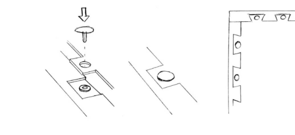
Concept number 3 and 4 are solutions similar to the one above but with the back panel fitted in an indented frame. There it can be attached with similar plugs from FAMILY B in premanufactured holes, where the holes are made in the indented frame. It can otherwise be attached with snap fittings instead. In these two concepts there will be no visible gap between the frame and the back panel, also the assembly is independent of which order it is being assembled. This concept is called The Indented frame and the two different solutions of it are shown in figure 9.
3. RESULT
Figure 9: Concept number 3 and 4. The concepts are similar and both called ”The Indented frame”.
Instead of having the back panel in FAMILY A as it is today, concept number 5 builds upon the idea that the back panel is another frame of board on stile that attaches with wedge dowel. This concept is called The Solid Frame nr 1 and is shown in figure 10. This solution eliminates the problem that the back panel can get offset. The important part in this design is that the top or the bottom has to be mounted last. The design will also be more stable since the back-part (back panel) is stiffer and stabilises the design even more. It will be more expensive compared to today’s product. The advantage with this design is that no snap fittings are needed and there will not be any gap between the frames and the back panel.
Figure 10: Concept number 5, ”The Solid Frame nr 1”.
Concept number 6 have one or two 90-degree angle on the edges (instead of 45 degrees as in FAMILY A). The order which the parts have to be assembled is
3. RESULT
more intuitive and more difficult to assemble the wrong way. With this solution the customer’s will easier realise which part should be placed where, without looking at the instructions. The back panel can be mounted as a last part, but the frames have to be mounted so that the 90-degree edges is pointed to the back. This concept is called The Solid Frame nr 2 and is shown in figure 11.
Figure 11: Concept number 6, ”The Solid Frame nr 2”.
Concept number 7 has a click function so that it is possible to assemble all the parts from the front. It will therefore not need any additional space from the side to wedge it in place. With plugs in the side frames and corresponding holes in the top panel. Four plastic fittings will then be pushed in to the holes of the top panel and lock on to the plugs. This concept is called The Plug-In-Plug and is shown in figure 12.
Figure 12: Concept number 7, ”The Plug-In-Plug”.
From benchmarking it appears that V¨alinge Innovation have an assembly solution that enables assembly of the frames from the front, called ”Threespine”. This solution has a good click on function which could be used at IKEA [21].
3. RESULT
The click function inspired to a new idea of using springs to attach the parts when assembling the furniture. A suggestion for how this could work is concept number 8, shown in figure 13. Having a spring in the groove of the top and bottom panel in FAMILY A, this spring will be able to lock the back panel in place. This could also allow for easy assembly with less fittings. The spring will be integrated in top and bottom panel whilst the back panel will have a L-shaped edge that can hook on to the spring once in place. The back panel can then be either as thick in the current design or be a bit thicker. As long as the part that goes in the groove is as the current design.
Figure 13: Concept number 8, spring function solution.
The idea of concept number 9 is to turn the wedge dowel 90 degrees and mount it on a extended part, as shown in figure 14. This solution could be used for mounting the parts from the front. This solution works unless the furniture is hanging on the wall in a certain direction. Therefore it is a better solution for wardrobes and furniture standing on the floor.
3. RESULT
Figure 14: Concept number 9, for wedge dowel mounted from the front. The idea of concept number 10 is to assemble the bottom panel with the help of a hooked formed geometry along one edge and the opposite side has a click function which connects the frames. The combination with a hook formed attachment and a click function stabilises the design in all directions. This make it possible to mount the last part from above and fit it with the back panel that is offset. This concept is called The Hook and is shown in figure 15.
3. RESULT
Concept number 11 has deeper grooves on both top and bottom. It would allow the back panel to slide further down if the customer assemble the furniture in the wrong order. Adding a red line on the back panel could indicate that the back panel should slide up before attaching the snap fittings to the back. This solution can be helpful to avoid getting a gap between top panel and back panel. The concept is called The Red Line and is shown in figure 16.
Figure 16: Concept number 11, ”The Red Line”. 3.5.2 Generated concepts for FAMILY B
FAMILY B has a round hole where the back panel slides down in. This hole is only visible on one side, and it is the side that is supposed to be faced down, so it is invisible once it is in place. Instead of having this as a round whole, concept number 12 would have the hole L shaped as it is shown in figure 17. The back panel slides into the groove through the hole and stabilises. The advantage in this solution is that the back panel will be more stable in the horisontal direction. Also making the visible hole smaller than the one in today’s design and a more stable back panel.
Figure 17: Concept number 12, circular groove on FAMILY B replaced with an L formed groove.
In today’s design of FAMILY B there is a gap between the wall and its top and bottom panel. To avoid seeing the gap from above, concept number 13
3. RESULT
makes the top panel flush with the sides and the wall. In this top panel there is a v-shaped groove so that when the customer slides the panel in place it fastens and stabilises. With the same plugs in today’s design the back panel is locked in place by tightening it in the bottom panel through premanufactured holes. This solution will eliminate the plastic plugs that locks the frame in the top panel. The number of loose fittings needed is therefore decreased. The concept is called The V-Shaped Groove and is shown in figure 18.
Figure 18: Concept number 13, ”V-Shaped Groove”.
In order to avoid the gap between the wall and the top/bottom panel on FAMILY B, concept number 14 makes the top/bottom panel flush with the sides. The top/bottom panel will have an indented edge which the back panel will be attached to with the same plastic parts as in today’s design of FAMILY B. This will make all the sides flush, so that the gap is eliminated. The number of loose fittings needed is decreased using this design. This concept is shown in figure 19.
3. RESULT
Figure 19: Concept number 14, FAMILY B with no gap between wall and shelf. 3.5.3 Generated concepts for back panel solution
Concept number 15 makes the assembly easier and more stable, the back panel will be made either a bit thicker or with sandwich material. The sandwich material will in that case have two HDF on the outside which is a bit thinner and honeycomb in-between the two HDF-panels. This will make it easier to assemble the back panel alone without any help because it will bend less than the current back panel. To avoid making the groove wider the back panel will be thinner in its edges, so it fits in today’s design. The thinner part that goes in the groove will be plan with the side that is visible once its assembled to avoid gaps. A sectional view of an example of a more stable panel is shown in figure 20.
3. RESULT
Figure 20: Concept number 15, a back panel stablilised with honeycomb mate-rial.
Concept number 16 is generated with the purpose of stabilising the back panel in larger designs. Here a stiff tape could be applied on the back. This tape will be applied by the customer before assembling the back panel in order to reduce the back panel bending. A down side with this is that there will be additional loose accessories i.e the tape. The tape could also be replaced by wood that is fixed in one side and rotate to lock it in place on the other side. The concept is shown in figure 21.
Figure 21: Concept number 16, a back panel stabilised with extra material. The line in the middle symbolise a hinge that makes the back panel foldable.
When a customer buys a larger product (for example wardrobe, shelf), it can be a problem assembling the back panel for the lack of space. To assemble
3. RESULT
it they will need twice the space in order to slide the back panel in place. To reduce this problem concept number 17 is generated, where one of the back panels side can have a ”jigsaw-tooth”-formation. The back panel could then be attached by tilting the side with no “teeth” and positioning it in the groove. Placing the side with teeth in the premanufactured cuts/holes and sliding it in place. The concept is called X-Y-Z Solution and is shown in figure 22.
Figure 22: Concept number 17, ”X-Y-Z Solution”
In concept number 18 the idea is to make a few cuts/holes in the back of the side frames, then manufacture the back panel so that there is some extra ma-terial (“jigsaw-tooth” formation) on the corresponding place of the back panel. Then placing the back panels “teeth” in the cut/hole and then sliding it in place. This will enable the customer to assemble it without using twice the space. The concept is called Puzzle and Slide and is shown in figure 23.
3. RESULT
Figure 23: Concept number 18, ”Puzzle and Slide”, a back panel with a tooth formed edge.
Concept number 19 is another solution with the “jigsaw-tooth” formation on the back panel but without the groove. It just have a few submerged parts (corresponding to the “teeth” on the back panel which it can be positioned in). The submerged part have preassembled plugs/holes in it where only the plastic heads (that fits into the assembled plug) that goes through the pre-assembled plugs comes as loose fittings. The plastic head goes through the premanufactured holes in the back panel into the plug that is preassembled in the submerged part of the frame and locks it in place. The concept is called Puzzle and Plug and is shown in figure 24.
3. RESULT
3.6
Selection of concept
The 19 different concepts and ideas are rated after presentation and discussed in the focus group. The papers that were handed out to the focus group is shown in appendix A. The rating and comments from the people in the focus group is found in appendix B. A summary of the votes from the group is shown in table 6.
Table 6: Concept scores given by the experts.
Concept 1 2 3 4 5 6 7 8 9 10 11 12 13 14 15 16 17 18 19 Participant 1 - - 1 4 3 - - - 2 - - 5 - - - - -Participant 2 2 - 5 5 - 1 - - - - 4 - - - 3 - -Participant 3 - - - 5 - - 4 - - - 3 - 1 - - - 2 - -Participant 4 - - 3 5 - - - 1 - 4 - - 2 - - - -Participant 5 - - 2 5 3 - - - 4 1 - - - -Participant 6 - - 4 5 - - - 1 - - - 2 - - 3 -Participant 7 2 - 4 1 - - 5 - - 3 - - - -PScore 4 0 19 30 6 1 9 2 0 7 13 1 3 5 2 0 5 3 0
The bar chart in figure 25 shows that concept number four (The Indented frame) gets the highest score. Concept number four is shown in figure 26 and is selected for further development.
3. RESULT
Figure 25: Each concept with scores given by the focus group with experts from IKEA.
Figure 26: Concept number four (the Indented frame).
3.7
Development of concept
To develop the Indented frame experts are consulted to get more details about the manufacturing process and possibilities. More information is obtained re-garding related parts for FAMILY A that are used for wall hanging and stacking of the furniture. The Indented frame size 35x35x35 is adapted to the additional
3. RESULT
components for wall mounting [22]. The holes for the rails are offset by 5 mm to fit the current components for wall mounting. A groove is added for the same reason. When it comes to stacking the furniture, the Indented frame is not adapted to the connection fittings [23]. The design of the components for stacking are considered easy to adapt to the new design of FAMILY A. Plastic fittings for fixing the wall mounting units onto the back of the Indented frame are modified. The plastic fittings are cut 3 mm, making it possible to fix it on the back before hanging it on the wall.
3.7.1 3-dimensional model
3-dimensional models are made in SolidWorks for visualisation and to create drawings for the new parts. The drawings for the Indented frame size 35x35x35 are sent to the pattern shop in IKEA to produce the first prototypes. Two different sizes of FAMILY A are made as 3-dimensional models and are shown in figure 27-33.
Figure 27: The 3-dimensional model assembly of the Indented frame, size 35x35x35.
3. RESULT
Figure 28: The 3-dimensional model of the assembled panels, size 35x35x35.
Figure 29: A close-up on the 3-dimensional model of the assembled panels, size 35x35x35.
3. RESULT
Figure 30: A close-up on the 3-dimensional model of the assembled panels with back panel, size 35x35x35.
Figure 31: The 3-dimensional model assembly of the indented frame, size 35x70x35.
3. RESULT
Figure 32: The 3-dimensional model of the assembled panels, size 35x70x35.
Figure 33: A close-up on the 3-dimensional model of the assembled panels, size 35x70x35.
3.7.2 Prototype
Prototypes are made in the pattern shop of IKEA of Sweden according to draw-ings made during the project. The prototype of the Indented frame is shown in figure 34.
3. RESULT
Figure 34: Prototype of the indented frame, size 35x35x35. 3.7.3 Calculations
A problem that might occur with the Indented frame regarding the snap fittings in the back, is reduction in stability. The snap fittings that stabilises the back panel will have less surface to attach to. This will lead to less stress between fitting and back panel which leads to less stability. The problem comes from the rough estimate, given by the deflection of a cantilever beam with a point load, calculated with
δ =FL
3
3EIβ (1)
and the stress is calculated with
σ = F
A (2)
[24]. From figure 35 and 36 it is seen how material from the frame is removed and takes away some of the contact surface. In equation 1, F=force, L=free length of fitting, E=Young’s modulus, β=factor of where the point load is lo-cated and I=area moment of inertia. In equation 2, A=snap fittings area that is in contact with the back panel.
3. RESULT
Figure 35: How the fitting sit in today’s model of FAMILY A, the hole is 13 millimeters deep.
3. RESULT
Figure 36: How the fitting sit in the Indented frame, the hole is 8 millimeters deep.
The new concept that has an Indented frame makes the hole which the fitting goes into five millimeters less deep. Therefore a rough estimate can be made by changing the free length of the fitting (the part that is not in the hole). This yields that the current free length is five millimeters and on the new concept it is ten millimeters. With the help of Matlab these two equation is solved for, with different data points and plotted. Figure 37 and 38 shows that the deflection of the fitting increases with the length (as expected) and the level of stress decreases with the length. This shows that the stress between the fitting and the back panel decreases and is therefore not as stable anymore. The force that is being used is the maximum recommended loading capacity for FAMILY A 35x35x35 which is 7kg [8].
3. RESULT 0 0.2 0.4 0.6 0.8 1 1.2 Deflection [mm] 0 2 4 6 8 10 12 14 16 18 20
Free length of fitting [mm]
Deflection of plastic fitting Deflection corresponding to its free length
Data points FAMILY A - modified FAMILY A
Figure 37: Deflection of a beam with a point load, calculated with different length (L) of the beam. The fitting has a semicircle cross-section.
3. RESULT
0 2 4 6 8 10 12 14 16 18 20
Free length of fitting [mm]
2.8 3 3.2 3.4 3.6 3.8 4 4.2 Stress [MPa]
Stress of plastic fitting
Stress corresponding to its free length FAMILY A
Family A - modified
Figure 38: Stress of a beam with length (L) and a semicircle cross-section.
3.7.4 Testing
The new way to assemble the furniture is presented in an instruction guide, shown in appendix C. The new instructions are presented step by step and compared to the current instructions. The result is that the new instructions have one step less than the current instructions. Furthermore, some of the remaining steps are simpler for the new instructions in the sense that the images contain less information than the current instructions. The new way to assemble this model from FAMILY A leads to a reduced assembly time. The assembly time for current design of FAMILY A, current design assembled the wrong order and the new concept is measured when four persons get to assemble the furniture. The results are presented in table 7.
Table 7: Assembly time for the current design and the new concept of FAMILY A.
Assembled by Person 1 Person 2 Person 3 Person 4 Current design 3 min 52 sec 2 min 20 sec 3 min 35 sec 2 min 45 sec
Wrong order 15 min 09 sec 14 min 40 sec 6 min 12 sec 9 min 25 sec New concept 3 min 16 sec 1 min 45 sec 3 min 10 sec 2 min 31 sec
3. RESULT
The furniture is mounted on the wall with corresponding wall mounting unit. The first load cell is connected between the loading machine and a metallic block, under the metallic block the second loading cell is connected. There is then a hard plastic block that separates the second loading cell and the furniture when pressure is applied. The setup is visualised in figure 39. The force is applied from above directed downwards, on the outer corner of the furniture to get the maximum pressure (worst scenario). The machine increases the pressure which elastically deforms the loading cells that collects the data and sends it to a computer.
Figure 39: Schematic of the test setup.
Two prototypes of Indented frame 35x35x35 and one from FAMILY A 35x35x35 are subjected to a load test in the test lab of IKEA. During the test the wall mounting bent and broke before the furniture. This happened on both the old and the new design. The wall mounting gave in after approximately 200 N. In figure 40, 41 and in table 8 the force which failure occured is presented for each tested model. The new design is approximately 5-10% weaker than current design, which can be seen in 40 and 41.
3. RESULT
Figure 40: Load test for the Indented frame prototyp 1 respectively 2. At what position corresponding to the applied force at each time is plotted. The load test setup was carried out as explained in section 2.7.3 ”Load test”. The force is increased with the deflection of the furniture, it is seen that when the furniture deflects the force is increased.
3. RESULT
Figure 41: Load test for current design. At what position corresponding to the applied force at each time is plotted. The load test setup was carried out as explained in section 2.7.3 ”Load test”. The force is increased with the deflection of the furniture, it is seen that when the furniture deflects the force is increased.
Table 8: Result from the testing, at what load the furniture fell down from the wall, due to weak wall hanging component.
Model Time when failure occur Force when failure occur
Prototype 1 95 s 206 N
Prototype 2 88 s 201 N
Current design 89 s 222 N
3.8
Concept evaluation
After doing the PDS score card it is seen that the new design is better than today’s. It has been improved in areas such as quality and sustainability. The score gained in each area of the PDS score card is summarised in a bar chart seen in figure 42. All questions for each area with respectively score can be seen in appendix D.
3. RESULT
Figure 42: Summary of the PDS score, current design compared with new design.
4. DISCUSSION
4
Discussion
Benchmarking the current designs of the furniture from IKEA was a good way to fully understand the problems that could occur for the customers. With the scope of the project in mind during the assembly, a lot of ideas were generated and written down immediately after the session. They were developed and discussed during the brainstorming session. It turned out to be an effective way to generate a good concept that is based on modifying a current design.
The patent research gave some ideas for the brainstorming session. Due to the difficulties and amount of time that it took to find adequate patents, it was not as effective as some of the other methods such as benchmarking. However, it did lead to two ideas which contributed to two concepts during the brainstorming. The keywords that was used to find the patents where based on some of the solutions that came up during the benchmarking as well as keywords from IKEA. The keywords generated a lot of results which made it a time-consuming process to go through the patents. Other keywords might have led to other/different generated concepts.
The goal was to improve easy assembly of furniture using wedge dowel. In the beginning of the project the goal was to generate two to three different ideas, therefore a lot of ideas were not focusing on FAMILY A only. After the experts scored the concepts there was a discussion in the project group if the first, second and third concept with highest scores should be developed at the same time. The decision was that only one concept was going to be developed further, due to the time limitation. It was more valuable to have a more developed solution for one concept than several less developed solutions. The testing would probably not have been achieved if several concepts had been developed at the same time.
Having a focus group was a productive and fast way of choosing a concept. Instead of going around and collecting all the necessary information in order to make a decision, all participants with knowledge in different areas was gath-ered in the same room. This also ensured that no important information was overlooked. It gave the project group new perspectives from people who work within other departments such as production, project management, design etc. As concept four received the highest score from most representatives in the group, this gives an indication that the concept is one of the most prominent ones. One plausible reason that concept four scored the highest might be due to the fact that the changes were easy and limited. Another reason could be that the experts had the scope and deadline of the project in mind. The con-cepts of FAMILY B where the bottom and top panels are flushed with the sides (see Figure 18 and 19) did not get a high score. The main reason for this was because of the gap, which helps prevent mold from spreading in homes where moist might occur in the walls. The gap also makes it possible for the customer to hide cables behind the shelf.
The snap fittings in today’s design of FAMILY A back panel is under de-velopment by IKEA. If it would be possible to adapt the fittings to the new concept, that would help stabilise the back panel even further. Since the milled
4. DISCUSSION
hole where the fittings goes into is smaller (this because the frame is thinner in that part). Note that the calculations are not made to get a true value. They were made with the purpose of showing that the level of stress in the fitting decreases which leads to less stability in the design. Also note that there are delimitation’s to the forces, shear forces are not included and the force acting on the fitting is just a point load from the back panel.
It is possible to adapt the new design in different ways in order to make it compatible with the existing components for example the snap fittings. This project deals only with one of them due to the time limitation. Other suggestions for developing the concept is to make a groove through the whole side of the panel for the wall hanging components. This modification would be made so that it could be implemented in today’s high-speed manufacturing process, also increase the gap width to avoid breakage of the milling tools. On the other hand a longer groove would probably make the design weaker. Other suggestions are to change the components or add material to the Indented frame in some way, before mounting the wall hanging components. The component that comes with FAMILY A made for stacking the furniture also needs to be adjusted. It will be shortened by 10 mm. This will lead to less material being used but a new article number will be created for this component. A paper foil also needs to be added on the milled surface to withstand moist in humid environments.
The assembly time is decreased for all persons who were clocked during this project. Despite the fact that the persons perform the assembly with different conditions, the new concept is assembled quicker. The time difference is about 30 seconds faster then the previous model of FAMILY A. Person 3 in table 7 assembled the current design in the correct way from the start, this person was then asked to do it the wrong way to measure the time difference. It took more time for the participants to read through and understand the instructions for current design than for the modified design. The main difference is that the panels for the new concept do not need to be assembled in a specific order and there is no risk of getting a gap between top and back panel. The wrong assembly order means that the furniture needs to be disassembled, which significantly increases the time of assembly and most likely make the customer frustrated. If this risk can be reduced, the average assembly time will be far lower than it is for the previous model of FAMILY A and the customers’ will hopefully be more satisfied with the assembly. One observation during the assembly test of the old design was that the persons did not see the difference between the frame panels. This might be a good reason why they assemble the furniture the wrong way. In view of this, another suggestion to help the customers’ even more with an easier assembly is to make all the four side panels exactly the same, with holes on one side and wedge dowels on the opposite side. The new concept is also easier to disassemble without instructions. This will facilitate the recycling process and transportation of bigger furniture, for example when the customer is moving.
The load test that was carried out during this project is a special test for the project’s sake and not according to the standards. The reason for this special test is that the standard test for furniture could not be implemented within
4. DISCUSSION
the time frame of the project. During the load test an error occured, the snap fittings on the back side hit the wall hanging component so that the force would be concentrated to that specific area. This was prevented by using two screws (made for adjusting the furniture so that it is horisontal) to distribute the force more. The problem here was that the force was still concentrated on these two screws so when pressure was applied it bent the wall hanging component after just 201 N, 206 N and 222 N respectively. This could be prevented if a new design of the wall hanging component was designed to maximise the force distribution or shortened the snap fittings. The prototype that was made during this project was made from a furniture that was bought at an IKEA store. This resulted in that the new holes had to be drilled to close to existing holes, which made the holes weaker. This could also have had an impacted, resulting in a weaker design. In figure 40 and 41 the applied force is a bit uniformed which can have to do with that the furniture deflected more which resulted in an increase of applied force and then bent back so that the force decreased again. It can also have to do with the selection of load cell which did not give the desired accuracy. The new design is approximately 5-10% weaker than today’s design, this is not a big issue since the assembly is much easier and eliminates the issue of assembling it the wrong way.
According to the PDS score card, the new design scored higher than a one on some of the questions. This means that the new design is slightly better than today’s and therefore worth to evaluate further. The main reason for the new design to score higher is because of the quick and easy way of assembling the furniture. It was not expected for it to score high on all questions because it is a modified design and not a complete new design. The projects objective was to improve easy assembly and this score shows that it was achieved.
5. CONCLUSIONS
5
Conclusions
• The new concept has a decreased assembly time and provides better condi-tions for completing an successful assembly without instruccondi-tions. The new design will therefore contribute to a more enjoyable and quicker assembly for the customer.
• During the load test of old and modified model the wall hanging compo-nent broke before the furniture could. The force distribution of the wall hanging is not optimal and could be improved by increasing the contact surface between wall mounting and furniture. Maximising and allocating the force distribution evenly over the furniture needs to be done.
• The Indented frame seems to be approximately 5-10% weaker than current design, but can still hold up against approximately 200 N when hanging on the wall.
• The new design fulfills almost all the desired requirements that were set at the beginning of the project. Further development needs to be done to apply the paper foil on the milled surface, in order for the design to withstand moisture.
• In order to implement the new design, more work needs to be done such as more adaptation to production, fitting of other components and more extensive furniture testing.
• It is easier to disassemble the new design which will facilitate the recycling process.
• Because of the symmetry of the new design, this will facilitate logistics during production. The parts are three instead of four different pieces. • According to the PDS score card the new design is better. The project
has fulfilled its objective by making the assembly easier and eliminate the need for assemble the furniture in a specific order.