Development of a web-based interface for SDH
Kalle Reimann
School of Innovation, Design and Engineering M¨alardalen University
Supervisor, ITTE Ericsson: Johan Henriksson Technical advisor, ITTE Ericsson: Anders Nyberg Supervisor, M¨alardalen University: Hans Bjurgren Examiner, M¨alardalen University: Mats Bj¨orkman
Abstract
Ericsson in Link¨oping has a test environment for testing telecommunica-tions equipment. New equipment was recently purchased to the fiber-optic network in the test environment, but the management system for the new equipment lacked a web based interface for users without special access to the system. The purpose of this thesis is to implement such an interface.
A web site based on Python and Django was built where users can search for circuits, with or without search filters, and get information about the matching circuits. The website has been live for two months and no major issues have appeared.
Acknowledgements
I would like to thank all of my colleagues at Ericsson, especially my super-visor Johan Henriksson, my technical adsuper-visor Anders Nyberg and the rest of the TENE team, my manager Svante Stadler, John Br¨annstr¨om for help-ing me with my programmhelp-ing questions, as well as Michael Holmgren and Michael Adams for helping me with the apartment. You were all friendly and helpful and made this thesis possible.
I also want to thank my advisor at M¨alardalen University, Hans Bjurgren. Finally, I want to thank Elin for her support.
List of Abbreviations
BSC Base Station ControllerBTS Base Station Transceiver CSV Comma Separated Values
GSM Global System for Mobile Communications LTE Long Term Evolution
MGW Media Gateway MS Mobile Station
MSC Mobile Switching Center PCM Pulse Code Modulation
PDH Plesiochronous Digital Hierarchy SDH Synchronous Digital Hierarchy SONET Synchronous Optical Networking TDM Time Division Multiplexing UML Unified Modeling Language XML Extensible Markup Language
Contents
1 Introduction 4 1.1 Background . . . 4 1.2 Problem formulation . . . 5 1.3 Purpose . . . 5 1.4 Requirements . . . 5 1.5 Target audience . . . 5 2 Theory 6 2.1 Telecommunications . . . 62.1.1 Plesiochronous Digital Hierarchy . . . 6
2.1.2 Synchronous Digital Hierarchy . . . 8
2.1.3 Ericsson test environment . . . 11
2.2 Django . . . 13 2.3 Fabric . . . 17 2.4 XML . . . 18 3 Method 20 3.1 Parser . . . 21 3.1.1 Background . . . 21 3.1.2 Implementation . . . 22 3.2 Server . . . 23 3.3 Website . . . 24 3.3.1 Design . . . 24 3.3.2 Sections . . . 25
3.3.3 Suggestions and requests . . . 28
4 Results 31 4.1 Requirements . . . 31 4.2 Design goals . . . 31 4.3 Future work . . . 32 5 Discussion 33 6 Conclusion 35
CONTENTS CONTENTS
A SDH basics 38
Chapter 1
Introduction
This thesis was conducted at Ericsson in Link¨oping as part of a Bachelor of Science, Degree Programme in Network Engineering.
1.1
Background
Ericsson is the largest provider of telecommunications equipment in the world, with more than 100,000 employees in over 180 countries [1]. The site in Link¨oping has roughly 1,500 employees, with the work mainly focused on development of GSM (2G) and LTE (4G) mobile networks, as well as simulations and tests of equipment. This thesis was arranged and supervised by the TENE (Test Network) team, which is a subsection of ITTE (IT/Test Environment) that supports and configures the test environment12.
The test environment was recently moved to a different building, due to lack of space as well as concerns that the building would not be able to handle the weight of the lab equipment. During the move, an opportunity was taken to upgrade the fiber optics equipment, as it was nearing 10 years in service. Another reason was to minimize the downtime of the test network. The new equipment is configured via a management system where only a few users can be given access, and unlike the previous system it lacked an alternative interface where users without this access can view network and configuration information.
1
Johan Henriksson & Anders Nyberg, personal communication, 2011-11-25 2Svante Stadler, personal communication, 2011-11-28
1.2. PROBLEM FORMULATION CHAPTER 1. INTRODUCTION
1.2
Problem formulation
The management system for a newly purchased fiber-optic network at Er-icsson’s site in Link¨oping has no alternative interface where users without special access can view network information.
1.3
Purpose
The purpose of this thesis is to develop a web based interface to the man-agement system that presents data about the network and does not require special access to view it.
1.4
Requirements
The minimum requirements for the final application were as follows: 1. The ability to search for circuits
2. Get management and operational information about these circuits 3. Well-documented source code to simplify future development of the
application
1.5
Target audience
The target audience is anyone with a basic knowledge of computer science, specifically computer networks, programming and databases.
Chapter 2
Theory
This chapter gives a brief theoretical background on multiplexing proto-cols in fiber-optic communications, and the various components used in this project.
2.1
Telecommunications
This section begins with a description of the multiplexing technology PDH and its drawbacks, which led to the development of the SDH standard. The section ends with a description of the test environment at Ericsson.
2.1.1 Plesiochronous Digital Hierarchy
The core telephone network was at one point all analog with voice signals transmitted as electrical voltage, but as technology advanced it was decided that it would be beneficiary to go digital, as it allowed the use of computers to manage the systems and because digital signals can be amplified and generated as new, unlike analog signals where any distortion present will also be amplified. In Sweden, for example, the switch to digital started with the development of the Automatic Cross-Connection Equipment (AXE) telephone exchange at Ericsson in the 1970s1.
Going digital requires that the voice signals are converted from analog signals to digital signals, and to accomplish this, Pulse Code Modulation (PCM) is used. It was decided that 3100 Hz (from 300 Hz to 3400 Hz) would be enough to carry a voice conversation, and with guard bands (which are used to keep the channels separate), each voice channel is set to 4000
1
2.1. TELECOMMUNICATIONS CHAPTER 2. THEORY
Hz. However, the Nyquist theorem states that to accurately reproduce an analog signal, the signal must be sampled at twice the highest frequency of the original signal. This means that the sample rate must be 8000 Hz (8000 samples/second or once every 125 µs). Each sample is then quantized (assigned) to an 8-bit value, which results in a digital voice channel with a bit rate of 64 kbit/s (8000 Hz * 8 bits). [2]
To carry multiple voice calls over the same medium, the signals are multiplexed using Time Division Multiplexing, where data from multiple sources is sent in sequence at a given interval. The multiplexing standard used in most countries is called the E-carrier system, while North America and Japan use the T-carrier system. The E-carrier system is a hierarchy of signal rates, and the basic signal rate (called level zero) is the E0, at 64 kbit/s, equal to one voice channel.
The E-carrier system, together with the T-carrier system, form the Ple-siochronous Digital Hierarchy (PDH), a multiplexing technology for trans-mitting data over fiber optic cables. Plesiochronous means “nearly syn-chronous” [3] and refers to the fact that in PDH, the equipment uses its own internal clock for synchronization, and there is no network-wide syn-chronization.
Table 2.1: E-carrier hierarchy [2]
Signal Bandwidth Number of 64 kbit/s channels Channels
E1 2.048 Mbit/s 32 32 * E0
E2 8.448 Mbit/s 128 4 * E1
E3 34.368 Mbit/s 512 4 * E2
E4 139.264 Mbit/s 2048 4 * E3
As seen in Table 2.1, an E1 signal consists of 32 64 kbit/s voice channels which are multiplexed during transmission. This is done by transmitting 8 bits from each voice channel every 125 µs in a round robin fashion (Channel 1, Channel 2, . . . , Channel 32, Channel 1, etc.). Thus, 8000 kHz * 8 bits * 32 channels = 2,048 (Mbit/s).
Each level in the E-carrier system contains some excess bandwidth (for example, E2 is 8,448 Mbit/s, but 4 * 2,048 (E1) is actually 8,192 Mbit/s). The excess bandwidth is used to recover in case an error in the synchro-nization occurs through a process called bit stuffing to bring the signals to a common bit-rate [2].
A higher-level is created from several lower-level signals by bit inter-leaving the lower-level signals. This means that the lower-level signals are combined on a bit-by-bit basis (compare this to how an E1 is created by byte interleaving several voice channels). Bit-interleaving multiplexing is a
com-2.1. TELECOMMUNICATIONS CHAPTER 2. THEORY
plex process which essentially makes individual lower-level signals “hidden” inside a higher-level signal, and make them complicated to extract.
The complexity of the multiplexing process is just one of the many draw-backs of PDH. The major issues are listed below [4].
1. To multiplex a 2 Mbit/s E1 signal to a 140 Mbit/s E4 signal, it’s necessary to traverse the entire hierarchy, meaning that the signal must first be multiplexed into a 8 Mbit/s E2 signal then into a 34 Mbit/s E3 signal, and then finally into an E4 signal. Accessing a single E1 signal within an E4 signal similarly requires the signal to pass through all the intermediate multiplexing stages.
2. Different hierarchies used in different parts of the world, requiring special equipment for interoperability.
3. Each vendor had their own proprietary TDM system.
4. E4 was the highest standardized signal rate (E5 existed, but imple-mentation differed between vendors).
5. Poor support for operation, administration and maintenance (OAM).
2.1.2 Synchronous Digital Hierarchy
The inherent issues with PDH led to a standardization process which re-sulted in the Synchronous Digital Hierarchy (SDH), a multiplexing standard used all over the world except in the North America and Japan, where the corresponding protocol Synchronous Optical Networking (SONET) is used, but the differences between them are relatively minor. [2]
SDH uses an extremely accurate centralized clock for timing purposes. Although there will be timing differences in the network, SDH has efficient mechanisms to deal with this, which will be discussed later on in this section. SDH defines a multiplexing hierarchy, seen in Figure 2.1, that begins with a E-carrier link (although SDH supports the encapsulation of other protocols such as ATM and IP) and ends up with a so called STM-N frame. The steps in the multiplexing hierarchy will be explained below.
Container (C)
The container is made up of a signal, such as an E1, which are called trib-utaries (meaning “a stream feeding a larger stream” [6]). The process of wrapping a signal in a container is called mapping. There are five different containers specified in the SDH standard, named C4, C3, C2, C11 and C12, and they correspond to the signal rates in PDH (Appendix A).
2.1. TELECOMMUNICATIONS CHAPTER 2. THEORY C-3 C-12 C-11 C-4 VC-3 VC-12 VC-11 TU-12 TU-3 TUG-2 TUG-3 VC-4 AU-4 AUG STM-N x3 x7 x3 xN 140 Mbit/s 45 Mbit/s 34 Mbit/s 2 Mbit/s 1.5 Mbit/s
Figure 2.1: SDH multiplexing structure as defined by the European Telecom-munications Standards Institute (ESTI) [5]
Virtual Container (VC)
The capacity provided by each container is greater than that of their ple-siochronous counterpart (for example the E4 rate of 139.264 Mbit/s vs. the C4 rate of 149.76 Mbit/s), so each container is padded with stuffing bits to produce a common bit-rate suitable for synchronous multiplexing.
Path overhead (“overhead” being another word for header ) is then added to the container, which contains management functions such as path status, alarms and error checking between the two end points. A container with stuffing bits and path overhead is called a virtual container (Appendix A). Tributary Unit (TU) & Administrative Unit (AU)
Although an SDH network is supposed to synchronous, in practice there’s still a risk that timing differences appear. To deal with this, virtual con-tainers are allowed to “float” freely inside STM-N frames, and even begin in one STM-N frame, and end in the next. Payload pointers are used to locate the start of a VC inside a frame in a process called aligning, and in the case of virtual containers 11, 12 and 3 (see Figure 2.1), this creates a tributary unit. A payload pointer added to VC-4 is called an administrative unit (Appendix A).
The use of pointers significantly simplifies the process of identifying in-dividual lower-level signals inside a multiplexed signal compared to the bit interleaved process in PDH (Appendix B).
2.1. TELECOMMUNICATIONS CHAPTER 2. THEORY
Tributary Unit Group (TUG) & Administrative Unit Group (AUG) Several TUs or AUs can be multiplexed to create tributary unit groups and administrative unit groups. These groups are then further multiplexed to create higher-order VCs, for example three TUG-3s are multiplexed to create a VC-4 (Appendix A).
Synchronous Transfer Module (STM-N)
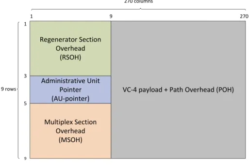
An AUG complemented with section overhead creates an STM-N frame. The section overhead consists of two sections, the regenerator section over-head (RSOH), which contains information used by every network element the signal passes through (such as repeaters and multiplexers), and the mul-tiplexing section overhead (MSOH), which contain information required by only the multiplexers. (Appendix A)
The N in STM-N represents how many AUGs have been multiplexed to create the frame. The basic unit in a SDH network is the STM-1, containing one AUG.
Table 2.2: Data rates supported by SDH [4]
STM-N rates STM-1 155.52 Mbit/s STM-4 622.08 Mbit/s STM-16 2588.32 Mbit/s STM-64 9953.28 Mbit/s STM-256 39813.12 Mbit/s
The bit-rate of an STM-1 frame is 155.52 Mbit/s and one frame is trans-mitted every 125 µs, or 8,000 frames/second (just like in PDH). This means that each STM-1 frame is 2430 bytes, and its often visualized in a rectan-gular shape consisting of 9 rows and 270 columns of bytes (9 * 270 = 2430), as seen in Figure 2.2 (Appendix A).
2.1. TELECOMMUNICATIONS CHAPTER 2. THEORY
Regenerator Section Overhead
(RSOH)
VC-4 payload + Path Overhead (POH) Administrative Unit Pointer (AU-pointer) Multiplex Section Overhead (MSOH) 270 columns 9 rows 1 1 3 5 9 9 270
Figure 2.2: STM-1 frame (Appendix A)
2.1.3 Ericsson test environment
As mentioned in the Background, the Ericsson test environment in Link¨oping is used for simulations and testing telecommunications equipment, with a focus on GSM (2G). This section contains short descriptions of the compo-nents in the network, with the topology seen in Figure 2.3.
Base Transceiver Station (BTS)
The mobile phone system is divided into geographic regions called cells (hence the name cell phone) and in the center of each cell is a Base Transceiver Station (also called Cell Site, or simply Base Station), where the antennas and transceivers are located and to which the mobile phones within range of the BTS transmit [7]. 150 BTSs are connected to the network.
Base Station Controller (BSC)
The BTSs are connected and controlled by a Base Station Controller which manages the radio resources of the cell. These management functions in-clude, for example, measuring the number of calls and the level of traffic and congestion for the cell, allocating radio channels for the calls and Mo-bile Station (MS) handover [7]. The development of BSCs is one of the main
2.1. TELECOMMUNICATIONS CHAPTER 2. THEORY
focuses of the site in Link¨oping, and there are roughly 140 of them in the test network. STM-1 STM-1 STM-16 STM-16 STM-1 STM-1 BSC MGW E1 E1 BTS TSS 870 870 BSC MGW E1 E1 BTS TSS 870 870 STM-1 STM-1 1664 MSC SIM2500 STM-1 STM-1 1664 MSC SIM2500
Figure 2.3: The (condensed) network topology of the test lab at Ericsson2
Mobile Switching Center (MSC)
There are four Mobile Switching Centers in the test network, and they man-age the calls in the mobile network. This includes setting up and routing the call, supervision, and call teardown. They also control other services such as SMS and FAX, and keeps track of the charge of the calls for billing purposes. The MSCs communicate with BSCs to organize call setup and arrange MS handover from one BSC to another [7].
Media Gateway (MGW)
The Media Gateway provides conversions of digital streams, for example from a circuit-switched E0 to a packet-switched VoIP call. It also has
2.2. DJANGO CHAPTER 2. THEORY
functions for reducing echo in calls and adds support for Dual Tone Multi-Frequency signaling (DTMF), also known as touch tone [8]. There are 11 MGWs in the network.
Traffic simulators (TSS & SIM2500)
These devices simulate voice calls and other types of transmissions, which is needed when testing the equipment.3 There are about 90 simulators connected to the network in total.
OMS1664 - Digital Cross-connect (DCS/DXS)
The OMS1664 is a model of Digital of Cross-Connect by Marconi (now owned by Ericsson). A DCS is designed to transfer lower-level signals from one higher-level signal to another, also known as circuit switching. Consider the topology in Figure 2.3, where the two DCSs are connected to BSCs over a STM-1 link. The connection between one BSC and one DSC contains a number of lower-level circuits, such as E1s, which all might have different destinations in the network. The circuits are transported in a STM-1 from the BSC to the DSC, where they are first demultiplexed and then multi-plexed again, and sent out different ports to their respective destination. [2] There are two DCSs in the network, both seen in Figure 2.3.
OMS870 - Add/Drop Multiplexer (ADM)
An Add/Drop Multiplexer is able to insert and drop tributaries to and from STM-N signals without affecting the rest of the traffic in the stream. This is, as mentioned previously, one of the major advantages of SDH over PDH, as the multiplexing/demultiplexing is done in a single step. [2] There are roughly 30 ADMs in the network, which are connected to BTSs and simu-lators over E1 links.
2.2
Django
Django is a web framework for creating dynamic websites using the pro-gramming language Python. It’s arguably the most popular web framework for Python [9], and a collection of websites powered by Django can be found at http://www.djangosites.org.
2.2. DJANGO CHAPTER 2. THEORY
Django is based on a Model-View-Template pattern, which separates the database management (in the model), the decision of which data on a web page should be displayed (in the view) and how the data should be display on the web page (in the template). This separation makes it easy to extend and reuse code for future projects. An explanation of the model, view and template follows.
Model
The model describes the data in a database, and in each model, attributes (also known as fields) are defined which map to columns in a database, while the model itself maps to a database table.
Listing 2.1: Django model
1 from django.db import models 2 from datetime import datetime 3 4 class Employee(models.Model): 5 first_name = models.CharField(max_length=50) 6 last_name = models.CharField(max_length=50) 7 age = models.IntegerField() 8 address = models.CharField(max_length=50) 9 hire_date = models.DateField() 10 11 def days_hired(self):
12 date_diff = datetime.today() - self.hire_date 13 return date_diff.days
We define an Employee model in Listing 2.1 with a number of attributes. Each attribute represents a column in our database (for example MySQL or PostgreSQL) and is given a field type, which in this case are CharField, IntegerField and DateField, and are used to set the column data type in the database. There’s also a custom method defined in the model class named days hired, which simply returns the number of days that an employee has been employed. [10]
View
The View describes which data is presented on a given page. For exam-ple, on an employee’s profile page, you might want to display the fields in the Employee Model (name, age, address, hire date), as well as every project the employee has been involved in, stored in a Projects Model.
When the user requests a certain profile page, the ID of the employee is captured from the URL (more on this later), which is used to get the Employee object (an instance of the Employee Model) associated with that ID. Using the employee ID, we can also get a list of Project objects that reference the employee.
2.2. DJANGO CHAPTER 2. THEORY
Listing 2.2: Django view
1 from django.http import Http404
2 from django.shortcuts import render_to_response 3 from company.models import Employee, Project 4
5 def profile(request, employee_id): 6 try: 7 employee = Employee.objects.get(pk=employee_id) 8 except Employee.DoesNotExist: 9 raise Http404 10 employee_projects = Project.objects.filter(employee = employee_id)
11 return render_to_response(’profile.html’, {’employee’: employee, ’projects’: employee_projects})
In Listing 2.2, a profile view is declared. It takes two parameters, request which is a Django request object, but can be thought of as a HTTP request (such as GET or POST). The second parameter is the employee ID, which is used to identify a specific employee.
The function starts with trying to get the Employee object associated with the ID, and if no such employee exist, it displays a HTTP 404 not found page. If it’s successful, however, it will continue and get all the Project objects associated with the employee ID. It’s not necessary to display an error page if no Project objects are found, because it’s possible that an employee has not been involved with any projects, which we will handle later on in the template. The view finally renders a template with the objects provided (the employee and his projects), and returns a HTTP response with the rendered template. [11]
Views are also closely related to another important concept in Django, namely the URL dispatcher. The idea is that when a user requests a web page at a certain URL, Django searches through a URL configuration file (URLconf), which maps regular expressions to Views. After running through the regular expressions in order, as soon as there is a match, it executes the corresponding View.
Listing 2.3: Django URLconf
1 from django.conf.urls.defaults import * 2
3 urlpatterns = patterns(’’,
4 (r’ˆ$’, ’company.views.index’),
5 (r’ˆprofile/(\d+)/$’, ’company.views.profile’), 6 )
URL patterns are relative to the base URL, which we in this case can assume to be http://www.example.com/. The example in Listing 2.3 contains two mappings. The first one has the regular expression ˆ$, and ˆ in regular expressions means “start of the line” and $ means “end of the line”. In
2.2. DJANGO CHAPTER 2. THEORY
other words, if there is no extra text after the base URL, execute the index View.
The regular expression ˆprofile/(\d+)/$ in the second mapping will look for the string profile, followed by a forward slash, one or more digits and then one final forward slash. \d+ means “one or more digits”, and it’s enclosed by parentheses which means that the value should be captured and sent to the View as a parameter. This is precisely what employee id in the profile View is. A URL that would be matched by this regular ex-pression is for example http://www.example.com/profile/86/, and 86would be sent to the profile View as employee id. [12]
Template
Finally, the Template describes how the data should be presented, which is accomplished using a special template language. The Template itself is nothing more than a text document, and while it’s primarily used to create HTML documents, it’s possible to create any type of document using it, for example XML or LATEX.
The template language supports simple control structures such as for-loops or if-statements, called block tags, and also variables to display dy-namic values. When the Template is rendered in the View, it basically replaces the variables in the Templates with the corresponding values from the view.
Listing 2.4: Django template
1 Name: {{ employee.first_name }} {{ employee.last_name }} <br> 2 Age: {{ employee.age }} <br>
3 Address: {{ employee.address }} <br>
4 Employed at company for {{ employee.days_hired }} days. <br> 5 Number of projects: {{ projects|length }}
6 {% for project in projects %} 7 <h4>{{ project.title }}</h4> 8 {% if project.completed %}
9 Status: Completed on {{ project.completion_date }} <br> 10 {% else %}
11 Status: Not completed 12 {% endif %}
13 {% endfor %}
The Template in Listing 2.4 mixes both Django template tags and HTML markup tags to create an HTML document when rendered. The View will pass in the employee objects and list of project objects. By enclosing a string in double curly brackets we declare that it’s a variable and should be replaced by a value. For example {{ employee.age }} will display the value of the age attribute of the employee instance that is currently being processed.
2.3. FABRIC CHAPTER 2. THEORY
The for-loop and if-statements at the end of the template are enclosed by curly brackets and percent signs, which denotes a block tag. The for-loop will iterate over all the projects that were extracted from the profile View. As previously mentioned, it’s possible that an employee has not been involved in any projects, and in that case the for-loop is skipped. The if-statement simply checks if project.completed is set to True, and in that case displays the completion date. [13]
Result
This simple web application might produce a page like this: Name: Kalle Reimann
Age: 25
Address: Vitm˚aragatan 3
Employed at company for 1024 days. Number of projects: 2
Development of a web based interface for SDH Status: Not completed
Computer networks, project course Status: Completed on 2010-06-02
2.3
Fabric
Fabric is a Python library used to aid the deployment of projects by simpli-fying the use of local and remote shell commands. In this project it is used to update the database used by the web reporter, which is done through a number of shell commands and scripts. By writing a script that makes use of the simple calls that Fabric provides, this process is made easy.
The commands used for this are local, which executes a command on the local host, and run, which executes a command on a remote host. Other useful commands include get (copy a file on a remote host to the local host), put (copy a file on the local host to a remote host) and sudo (run a command on a remote host as superuser). [14]
Listing 2.5: Simple script using Fabric 1 from fabric.api import run, env 2
3 env.hosts = [’host1@ericsson.com’, ’host2@ericsson.com’] 4 env.warn_only = True
2.4. XML CHAPTER 2. THEORY
6 def get_sys_info():
7 result = run(’uname -a’) 8 if result.failed:
9 print ’Execution failed’ 10 else:
11 print result
The example in Listing 2.5 will execute the shell command uname -a on the hosts host1@ericsson.com and host2@ericsson.com. By set-ting warn only to True, we specify that that we want to use custom error handling, instead of aborting the script as soon as an error occurs. run will return the result of the remote command’s standard output, and as-sign it to the variable result. result also gets a special boolean flag, result.failed, which is set to True if the command failed. In this case, the script checks if the command failed, and then prints a custom error message. If the command succeeded though, we print the output from the command.
Note that every time this script is run, the passwords to host1 and host2must be entered manually, so it’s recommended to setup SSH public key authentication if the process is supposed to be automated.
2.4
XML
Extensible Markup Language (XML) is just like the name says a markup language and is in many ways similar to HTML. While HTML describes how to display content, XML describes the content itself by storing data in a structured manner.
Listing 2.6: Example of an XML document 1 <network>
2 <host name=’host1’>
3 <subnetwork id=’12’> 4 <ip_address> 5 192.168.12.1 6 </ip_address> 7 </subnetwork> 8 </host>
9 <host name=’host2’>
10 <subnetwork id=’13’> 11 <ip_address> 12 192.168.13.1 13 </ip_address> 14 </subnetwork> 15 </host> 16 </network>
An XML document is made up of a number of elements, which is the content between an opening tag and a closing tag, including the tags themselves.
2.4. XML CHAPTER 2. THEORY
An element can contain other elements, text, a combination of both, or be empty. An element that is contained within another element is a child element to a parent element. The example in Listing 2.6 describes a simple network where the elements are colored in blue and include network, host, subnetwork and ip address. There is always a single root element in an XML document which contain all other elements, and in this case it’s network.
Just like HTML, XML elements can contain attributes. The attribute names in the example are marked in orange and the attribute values are marked in purple. The IP address values in the example are simply referred to as text content. There are no major differences between attributes and text content, it’s up to the creator of the document to decide whether a value should be an attribute or text content. [15]
Chapter 3
Method
The thesis was divided into three phases. 1. Pre-study
The first week of the project was spent reading up on the basics of SDH. This was done through lectures by Ericsson employees as well as educational material from Ericsson and Telia. An email was also sent to the various sections at Ericsson, asking if there are any specific features they would be interested in for the new web reporter.
2. Evaluation of XML database and implementation of parser
During this phase, the XML database was examined and a method to access it was implemented.
3. Implementation of web frontend
The final phase was to build the website and get it to interact with the database.
The programming language chosen for this project is Python. The rea-sons being that it produces simple and readable source code, and has a large standard library and many third-party libraries. It’s also a program-ming language that already being used internally at Ericsson. The source code in this project closely follows the PEP 8 style guide.1
To create the website, the Python web framework Django is used. There are a lot of web frameworks for Python to choose from, but as mentioned in Section 2.2, Django is probably the most popular and has a large and
1
3.1. PARSER CHAPTER 3. METHOD
comprehensive documentation, which was the major reason it was chosen, as many questions and problems would undoubtably arise during the project, and easy access to information would be essential.
ServiceON Network Manager is the management system used in the newly installed fiber optics equipment, which allows for configuration and monitoring of the network. It contains an interface called PSB-NI for out-putting information from the system as XML documents (which will be re-ferred to as the XML database) through the applications NETINFO, which outputs information about the network in its current state, and CLIFE, which outputs a history of the circuits in the network. NETINFO is what will be used for this project.
The design goals of the application were:
1. Code readability. Make it as easy as possible to maintain and modify the code in the future.
2. Performance. No one likes a slow website.
3. Stability. Any application used in a work environment should be stable and reliable.
3.1
Parser
This section explains how the interface to the XML database works.
3.1.1 Background
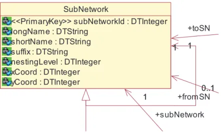
The first order of business during the development of the parser was to examine the XML database. PSB-NI has a fairly detailed user manual de-scribing the XML documents (each XML document can be seen as a table in a relational database), with UML class diagrams that show the relationships between them as shown in Figure 3.1.
Some key facts about the XML database:
1. It is static and is only updated when the NETINFO application is run. 2. It consists of several XML documents, which reference each other
through ID numbers or other identifiers.
3. The number of records in each file range from a couple of hundred to several thousands.
4. It will continue to grow slowly but steadily. At the start of the project the total file size was roughly 30 megabytes and at the end of the project it had reached a size of 35 megabytes.
3.1. PARSER CHAPTER 3. METHOD
SubNetwork
<<PrimaryKey>> subNetworkId : DTInteger longNam e : DTString s hortName : DTString s uffix : DTString nestingLevel : DTInteger xCoord : DTInteger yCoord : DTInteger 0..1 0..1 1 +toSN 1 1 +from SN 1 1 +subNetwork 1
Figure 3.1: UML class diagram of the XML database
With an understanding of how the database is organized, the development of the parser began, and the idea is to import the XML-based database to an SQL-based database, in this case MySQL. Having the data in an SQL database would simplify the coding effort, both for this project and in the future, as Django has a nice object-relational mapping (ORM) for working with SQL-databases, and SQL is a well-known and popular query language.
3.1.2 Implementation
The parser is a Python script where a dictionary, elements, first is de-clared. A dictionary in Python is a mapping between a key and a corre-sponding value. The keys of the elements dictionary is the name of the XML documents (and also the name of the tables in the database). The value to each key is a dictionary as well, which maps the database field name to the XPath query to extract the value. XPath is a query language for XML files for extracting values.
Listing 3.1: Mapping between field names and XPath query 1 elements = { 2 ‘Path’: 3 { 4 ‘CircuitLO’: ‘@Id’, 5 ‘pathId’: ‘Path/Path.pathID/*/text()’, 6 ‘pathname’: ‘Path/Path.username/*/text()’, 7 ‘payload’: ‘name(Path/Path.payLoad/*/*)’, 8 ‘customerData’: ‘Path/Path.customerData/*/text()’ 9 } 10 }
3.2. SERVER CHAPTER 3. METHOD
The following is a description of the control flow of the parser: It begins by iterating over every XML document, and for each record in the current XML document (for example each Path in Path.xml), use the XPath queries specified for that document to extract the associated values. Each extracted value is put in a dictionary with its associated attribute name.
Listing 3.2: The list of dictionaries after parsing one XML document 1 parsed_xml = [
2 {
3 ‘pathId’: 1,
4 ‘pathName’: ‘Example circuit 1’, 5 ‘payload’: None
6 }, 7 {
8 ‘pathId’: 2,
9 ‘pathName’: ‘Example circuit 2’, 10 ‘payload’: None
11 } 12 ]
Listing 3.2 shows a simple example of the result from parsing one XML document. All the values are stored in dictionaries which in turn are stored in a list, which provides easy access to the contents of the document.
The next step is to write the values to a CSV (comma separated values) file, which as the name implies, is simply a text file with a number of values that are separated by a common delimiter (it does not have to be a comma, in fact it’s a tab character in this script). After all the XML documents have been converted to CSV files, the script truncates the relevant tables in the MySQL database to prepare it for the new data. It then calls the external application mysqlimport2 which imports the CSV files into the database,
and at this point, the database is up to date.
3.2
Server
The application is hosted on a virtual server running the SUSE Linux distri-bution. The database is updated through the use of script using the Python module Fabric, which is executed every 15 minutes using cron.
1: The script for outputting the XML documents is executed, along with a configuration file where it’s specified which parts of the management sys-tem should be included. This produces the following five XML documents:
3.3. WEBSITE CHAPTER 3. METHOD
AccessPoint.xml, CrossConnection.xml, NetworkElement.xml, Path.xmland Subnetwork.xml.
2: Every XML document contains a Summary element, which contains a time stamp of when the file was generated. This causes an issue when checking if there are any changes to the files, as every time the documents are generated, the time stamps are updated, and thus the files have changed. This will cause the database to be updated every time the script is run, even though there are no actual changes to the network. To solve this, a sedcommand is run on every XML document generated, which looks for a regular expression that matches the Summary element, and removes it from the document. Now, if no changes have been made to the network between two consecutive executions of the script, the generated XML documents will be identical, and the local database will not be updated.
3: rsync is a program that syncs the contents of a directory on one host with the contents of a directory on another host. If any changes have been made to the files on the source directory, only the changes to the files (in other words, not the entire file) will be sent to the destination host. The files on both hosts will then be identical. The server running ServiceON Network Manager is in this case the source while the web server is the destination.
4: The script checks if rsync updated any files on the web server, and if no changes were made, the script exits. Otherwise, it continues on to the next step.
5: The script described in the previous section is run and the database is updated.
If an error occurs at any step, the script will output a warning message and abort. The warning message is displayed on the front page of the web reporter to alert the users that the database might not be up to date. The error message will remain for as long as the script fails to execute, and is removed the next time the script is executed successfully.
3.3
Website
3.3.1 Design
Ericsson has a number of brand identity documents available on the internal corporate network. The documents contain guidelines for the proper use of design elements such as fonts, colors and graphics, and also include assets such as icons and various templates. Although it was not a requirement from Ericsson, these documents were followed as closely as possible.
The basic design of the website is based on the design of http://www. ericsson.com, while the layout of the front page is inspired by the front
3.3. WEBSITE CHAPTER 3. METHOD
page of Google3. The idea is to have a clean and simple interface where the users are not overwhelmed by options. The old web reporter had, according to those who used it, an excessive amount of search options and information presented. Those questioned only needed an option to search for circuit names, and this is the only search option that the web reporter provides. It’s however possible to filter the circuits based on a number of search options. These search options are by default hidden, and only shown when Advanced Search is selected.
The font of the “SDH web reporter” logo on the front page is Ericsson Capital, which is the recommended font for headers in the guidelines. The logo toggles between five different gradients which are the secondary Erics-son brand colors, as seen in Listing 3.2. The primary brand colors are white and dark blue, as seen in the Ericsson logotype.
Figure 3.2: The secondary Ericsson brand colors
JavaScript
The JavaScript libraries jQuery4and jQuery UI are used to improve the user experience and provide visual flair. jQuery is used to hide and show elements on the web page, which can be seen on the front page when enabling and disabling the advanced search options. jQuery UI is an extension to jQuery and provides the autocompletion feature as well as the calendar under the advanced search options used to limit the creation date of the circuits.
3.3.2 Sections
This is a rundown of the various sections of the website. Front page
The front page provides several search options:
3
http://www.google.com 4http://jquery.com/
3.3. WEBSITE CHAPTER 3. METHOD
1. Search for a circuit name, or part of a circuit name
2. Search for circuits connected to a specific network element 3. Search for circuits created before, after, or between two dates
None of these options are mandatory, and in other words it’s possible to leave all of the options empty which will return all the circuits in the network.
Searching was initially slow, and could take up to 30 seconds to return the results, but after adding MySQL indexes5 it usually takes less than a second.
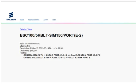
Details
The search results page displays a list of circuits matching the search criteria with links to a page with details about the circuit. This page offers two views; basic and detailed. The basic view displays information that should be sufficient for most users, such as network elements connected to the circuit along with slot and port ID. The detailed view on the other hand displays essentially every piece of information about the circuit from the database.
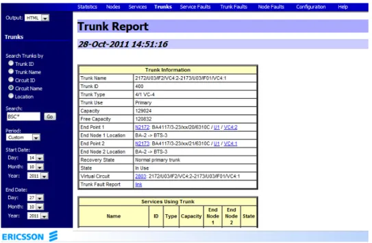
Figure 3.3: Front page of the former web reporter
5
3.3. WEBSITE CHAPTER 3. METHOD
Figure 3.4: The front page of the new web reporter
3.3. WEBSITE CHAPTER 3. METHOD
Figure 3.6: The basic view for a circuit Abbreviations, About & Help
There is a myriad of abbreviations in the telecommunications world, and it’s difficult to remember all of them. For this reason there is a page showing the most common abbreviations that might show up in the web reporter, along with their meaning. There is also an About page and a Help page, whose contents should be obvious.
3.3.3 Suggestions and requests
The following is a description of some of the more notable suggestions and requests that were received.
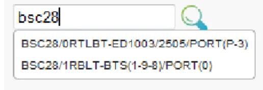
Auto completion
Auto completion of circuit names in the search box has been implemented to aid users when searching. When a user is searching for a circuit, for example BSC21/122RBLT-BSC21/123RBLT, after the user has typed the first four letters, “BSC2”, a box with matching circuits pops up. If are there more than ten matching circuits, the suggestion box groups together circuits, so that if the input “BSC2” returns many results, the suggestion box might display “BSC2, BSC22, BSC27, BSC202”. If there are less than ten matching circuits, the full circuit names of the matching circuits are displayed.
3.3. WEBSITE CHAPTER 3. METHOD
Figure 3.7: Auto completion showing an abbreviated list of matches
Figure 3.8: Auto completion showing the full names of the matching circuits Wild card search
The previous web report did an exact search for the search query, meaning that if a user searched for “BSC”, it would only display circuits named exactly that. The new web reporter, however, by default matches all the circuit names with the search query as a substring. In other words, searching for “BSC” will return every circuit whose circuit name contains the substring “BSC”.
To get this functionality in the previous web reporter, one would have to use wild cards, “*”. The new web reporter still supports wild cards though, and while the search query “*BSC*” is identical to “BSC” (as both search for circuits containing “BSC”), the use of wild cards can be help-ful when searching for circuits containing two separate substrings, such as “BSC*MGW”.
Excel
There are a number of test tools connected to the network, for example sim-ulators to simulate phone calls. The users who work with these tools have a document which list which tool is connected to what network element, and on which port and slot. Previously, this document had to be manu-ally updated, which was a hassle, and some users wanted this to be done automatically in the new web reporter.
3.3. WEBSITE CHAPTER 3. METHOD
Table 3.1: Parsing the circuit BSC72/120RBLT-6/PORT(1)/LENA09
Port Slot Connector Dip Tool
2 4 BSC72 120RBLT LENA09
At the time of the project, all the test tools were connected to a sin-gle ADM, and by checking the name of every circuit passing through that multiplexer, it’s possible to get a list of all the tools in the network. A tool can only be identified by looking at the name of the circuit, and by using regular expression to parse the name of the circuit, the relevant values can be extracted.
Using the Python module xlwt, an Excel document is created which the user can download. This make the generation of the document automatic, always containing the latest information from the database.
It should be noted that because it’s parsing text strings, this function is extremely sensitive to any misspellings or changes to the formatting of circuit names. This shouldn’t be a major issue in practice though, as fixing the name of a circuit is a simple procedure.
Chapter 4
Results
4.1
Requirements
1. The ability to search for circuits
The application is able to search for circuits.
2. Get management and operational information about these circuits
The application presents both basic and detailed information about the circuits.
3. Well-documented source code to simplify future development of the application
The source code is well-documented.
4.2
Design goals
1. Code readability
The code has been thoroughly commented, verbosity has been favoured over cleverness (as clever tricks in the code tend to degrade readabil-ity), and a user manual has been written that documents the applica-tion, which includes the Fabric script, parser and Django files.
In certain sections, the code is designed to accommodate likely future changes, such as the test tools being connected to a single multiplexer, as mentioned in Section 3.3.3. The only modification needed if another multiplexer is added is to add the ID of the multiplexer to a list in the code.
2. Performance
With the current implementation, it takes 20-30 seconds to update the database. This includes everything from running the script for
4.3. FUTURE WORK CHAPTER 4. RESULTS
generating the XML documents on the remote server to importing the CSV files into MySQL. This is somewhat unfortunate, but it shouldn’t affect the end users, as the website is still functional during the process. The website itself is fast and responsive, and searches take one to two seconds to complete. The website should stay responsive, even as more circuits are added, thanks to the MySQL database.
3. Stability
At the time of writing this, the website has been live for almost two months, and while bugs have popped up (that have been fixed), there are no signs of instability.
4.3
Future work
In the detailed view for each circuit, the names of the values (such as “NEIdOnNM” or “LayerSN”) are taken directly from the database, and has caused some confusion to the users. Some names have been exchanged for more human friendly names, but in many cases the names have been difficult to decipher. This should be looked into in the future as the de-tailed view is of limited use if the users don’t understand what the values represent.
A common request that was scrapped due to being somewhat out of scope for the project and a lack of time, was a page displaying alarms in the network. These are logged in a database separate from circuit information using a different structure (not XML), and would require a new parser.
Chapter 5
Discussion
It could be argued that parsing the XML documents and then importing them into MySQL is not the most elegant solution as it adds extra perfor-mance overhead in both time and space. The preferable way of accessing the database might have been to simply query the XML documents on demand, when the users request the information. XQuery1 is a query and
program-ming language for XML which at first looks like a good solution for this, but it came with a number of drawbacks.
First and foremost it meant having to learn a new programming language on an already tight schedule. It also increases the difficulty for anyone who in the future wants to modify the code, and last but not least, it might even degrade the performance. Certain search queries requires that all five XML documents (or tables in MySQL) are scanned, and while this is done in almost an instant with an SQL-database, it will almost certainly take a significantly longer time with an XML-based database. For these reasons, XQuery was put on the shelf, and other alternatives were explored.
Another method that initially looked promising was the LOAD XML INFILE2 statement in MySQL, which imports an XML file into MySQL. Two issues immediately arose, however, making it not seem like a viable solution.
First of all, the LOAD XML INFILE statement only supports simple and well-formed XML documents, of which the XML documents generated by the management system is neither. There are for example cases where the XML generated is not even valid according to the W3C recommendation [16], as shown in Listing 5.1 where the value true is stored inside a markup tag,
1http://www.w3.org/TR/xquery/
CHAPTER 5. DISCUSSION
and MySQL would unforunately be unable to extract this value.
Listing 5.1: Non-valid XML present in the XML documents 1 <Element>
2 <DTBoolean>
3 </DTBoolean.true> 4 </DTBoolean>
5 </Element>
The second reason was that the version of MySQL (5.1) running on the central database server simply doesn’t have support for LOAD XML INFILE. Therefore other options were explored.
Chapter 6
Conclusion
The purpose of this thesis has been to implement a web-based interface to a management system. The final application meets the requirements and has been online for two months without any major issues. The choice of Python and Django as the basis for the website proved to be successful combination, as it provided a quick and simple way of developing the website and testing new features, yet was powerful enough to do what was required.
Most features requested by the users have been implemented, for example certain search filters and the ability to download an Excel document with a table of how networks tools are connected to the network.
The website is fast and responsive, and while it might take up to 30 seconds to update the database, this doesn’t affect the end users as the website is functional during this time.
Bibliography
[1] Ericsson.com, Company factshttp://www.ericsson.com/thecompany/company_facts Last accessed: November 25, 2011
[2] Alwayn, Vivek. Optical Network Design and Implementation ISBN: 978-1587051050
Indianapolis: Cisco Press, 2004
[3] Dictionary.com, Plesiochronous — Define Plesiochronous at Dictio-nary.com
http://dictionary.reference.com/browse/ plesiochronous
Last accessed: November 13, 2011
[4] Tektronix, SDH Telecommunications Standard Primer
http://www.tek.com/Measurement/App_Notes/sdhprimer/ 2RX_11694_2.pdf
Last accessed: November 13, 2011
[5] European Telecommunications Standards Institute (ETSI), Syn-chronous Digital Hierarchy (SDH) multiplexing structyre
http://www.etsi.org/deliver/etsi_i_ets/300100_ 300199/300147/01_60/ets_300147e01p.pdf
Last accessed: December 5, 2011
[6] Merriam Webster, Tributary - Definition and More from the Free Merriam-Webster Dictionary
http://www.merriam-webster.com/dictionary/ tributary?show=1&t=1298147913
Last accessed: November 10, 2011
[7] Ericsson Radio Systems AB, GSM Site Survey
[8] Freeman, Roger L. Fundamentals of Telecommunications ISBN: 0-471-71045-8 Hoboken: John Wiley & Sons, 2005
BIBLIOGRAPHY BIBLIOGRAPHY
[9] HotFrameworks.com, Python web frameworks rankings http://hotframeworks.com/languages/python Last accessed: November 21, 2011
[10] Django Documentation, Models
https://docs.djangoproject.com/en/1.3/topics/db/ models/
Last accessed: November 21, 2011 [11] Django Documentation, Views
https://docs.djangoproject.com/en/1.3/topics/http/ views/
Last accessed: November 21, 2011 [12] Django Documentation, URL dispatcher
https://docs.djangoproject.com/en/1.3/topics/http/ urls/
Last accessed: November 22, 2011
[13] Django Documentation, Template language
https://docs.djangoproject.com/en/1.3/ref/ templates/api/
Last accessed: November 22, 2011 [14] fabfile.org, Fabric 1.3.3 documentation
http://docs.fabfile.org/en/1.3.3/index.html Last accessed: December 7, 2011
[15] W3Schools, XML tutorial
http://www.w3schools.com/xml/ Last accessed: December 7, 2011
[16] W3C recommendation, Extensible Markup Language (XML) 1.0 (Fifth Edition)
http://www.w3.org/TR/REC-xml/ Last accessed: December 3, 2011
![Table 2.1: E-carrier hierarchy [2]](https://thumb-eu.123doks.com/thumbv2/5dokorg/4861357.132306/10.892.196.701.646.753/table-e-carrier-hierarchy.webp)
![Figure 2.1: SDH multiplexing structure as defined by the European Telecom- Telecom-munications Standards Institute (ESTI) [5]](https://thumb-eu.123doks.com/thumbv2/5dokorg/4861357.132306/12.892.184.713.197.415/multiplexing-structure-european-telecom-telecom-munications-standards-institute.webp)