Flexible and Printed Electronics
PAPER • OPEN ACCESS
A ferroelectric polymer introduces addressability in electrophoretic
display cells
To cite this article: Negar Sani et al 2019 Flex. Print. Electron. 4 035004
View the article online for updates and enhancements.
PAPER
A ferroelectric polymer introduces addressability in electrophoretic
display cells
Negar Sani1 , Déborah Mirbel2 , Simone Fabiano1 , Daniel Simon1 , Isak Engquist1 , Cyril Brochon2 , Eric Cloutet2 , Georges Hadziioannou2and Magnus Berggren1
1 Department of Science and Technology, Linköping University, SE-60174 Norrköping, Sweden
2 Laboratoire de Chimie des Polymères Organiques(LCPO), Université de Bordeaux, CNRS (UMR 5629), INP Bordeaux-Allée Geoffroy Saint Hilaire, Bât B8, CS 50023, F-33615 Pessac Cedex, France
E-mail:simone.fabiano@liu.se
Keywords: ferroelectric, electrophoretic display, passive matrix display Supplementary material for this article is availableonline
Abstract
During the last decades, tremendous efforts have been carried out to develop
flexible electronics for a
vast array of applications. Among all different applications investigated in this area,
flexible displays
have gained significant attention, being a vital part of large-area devices, portable systems and
electronic labels etc electrophoretic
(EP) ink displays have outstanding properties such as a superior
optical switch contrast and low power consumption, besides being compatible with
flexible
electronics. However, the EP ink technology requires an active matrix-addressing scheme to enable
exclusive addressing of individual pixels. EP ink pixels cannot be incorporated in low cost and easily
manufactured passive matrix circuits due to the lack of threshold voltage and nonlinearity, necessities
to provide addressability. Here, we suggest a simple method to introduce nonlinearity and threshold
voltage in EP ink display cells in order to make them passively addressable. Our method exploits the
nonlinearity of an organic ferroelectric capacitor that introduces passive addressability in display cells.
The organic ferroelectric material poly(vinylidene fluoride-co-trifluoroethylene) (P(VDF-TrFE)) is
here chosen because of its simple manufacturing protocol and good polarizability. We demonstrate
that a nonlinear EP cell with bistable states can be produced by depositing a P(VDF-TrFE) film on the
bottom electrode of the display cell. The P(VDF-TrFE) capacitor and the EP ink cell are separately
characterized in order to match the surface charge at their respective interfaces and to achieve and
optimize bistable operation of display pixels.
1. Introduction
With an increasing demand for thin,flexible, light-weight electronics on the market, a major research effort is directed towards developingflexible displays that run at low power consumption protocols and are possible to produce using a simple and low-cost fabrication process [1–7]. Electrophoretic (EP) inks have been considered as one of the candidates for such applications due to their ability to be integrated with flexible electronics, superior optical properties and low power consumption when incorporated in EP image displays(EPIDs) [8–10]. The EP ink technology consists of colored charged particles in an inert media that is encapsulated between a rear and a transparent
top electrode. Upon applying voltage to the electrodes, the charged particles migrate, according to electro-phoresis, towards the electrode with the opposite polarity causing the cell to adopt the color of the particles that accumulate along the transparent top electrode.
A display device consists of individual pixels that are exclusively addressable to enable updating of the image to be displayed. Commonly, matrix addressing is utilized, which is a technology concept that includes pixels that are arranged in a 2D cross-point matrix. Individual pixels are addressed via row and column lines. There are two main approaches for matrix addressing: active matrix (AM) and passive matrix (PM) addressing. AM addressing is a mature
OPEN ACCESS
RECEIVED
18 March 2019
REVISED
31 July 2019
ACCEPTED FOR PUBLICATION
29 August 2019
PUBLISHED
12 September 2019
Original content from this work may be used under the terms of theCreative Commons Attribution 3.0 licence.
Any further distribution of this work must maintain attribution to the author(s) and the title of the work, journal citation and DOI.
technology that has been used for displays since the first liquid crystal displays were introduced to the mar-ket[11]. In an AM display, an active element i.e. a thin film transistor (TFT) is used as a switch in each pixel. PM addressing has a simpler architecture as compared to the AM; the crossing between a row electrode and a column electrode together with the characteristics of the pixel device is utilized to achieve addressability. Since PM does not require any active addressing cir-cuitry in each pixel, it is tempting to consider PM addressing before AM ditto, since a PM addressing cir-cuit is relatively much simpler and enables a fabrica-tion protocol of lower cost. However, addressability in a PM scheme requires pixels with a current–voltage and switching characteristic that is strongly nonlinear.
Several approaches have been demonstrated for AM addressing of EPIDs among which the technolo-gies based on organic materials are promising due to their compatibility withflexible and printed electro-nics[12–16]. PM addressing has been used for display technologies that are based on pixel elements that have some intrinsic nonlinearity such as light emitting diodes(LEDs) and ferroelectric liquid crystals. How-ever, very few approaches have been reported on uti-lizing PM addressing in EPIDs[17–19]. In general, it is believed that since EPID pixels do not exhibit an inherent current–voltage threshold they are not good candidates for PM addressing. A possible solution would be to use a nonlinear element in combination with the linear EPID pixel in order to introduce the desired threshold characteristics in the current–volt-age characteristics of the pixels. Lilja et al have used two diodes to add nonlinearity in EPIDs, introducing an extra layer of complexity to the system[19]. Here, we report a simple approach to implement nonlinear I–V characteristics in IPED pixels using a thin film of an organic ferroelectric polymer.
Ferroelectric polymers belong to a class of materi-als with permanent electrical dipoles that can gain a stable polarization by applying an electricfield. Ferro-electrics are used in a variety of applications including sensors, microsystems, memories and high frequency electrical components[20,21]. Work on organic fer-roelectrics and their applications started in the 1980s; however, only in the past few years researchers boos-ted investigating organic ferroelectrics mainly as a solution for downscaling problem of conventional electronic memories[22–24]. Among the ferroelectric polymers, poly(vinylidene fluoride) (PVDF) and its copolymers with the trifluoroethylene (TrFE) moiety have been the center of interest for many research stu-dies[25]. This is due to the particular properties of poly(vinylidene fluoride-co-trifluoroethylene) (P (VDF-TrFE)) including simple, low temperature and solution-based processing and stability beside the gen-eral advantages of organic materials such as being flex-ible and feasflex-ible for large scale manufacturing[24,25]. P(VDF-TrFE) has been incorporated in ferroelectric capacitors [26, 27], TFT [28–30] and diodes [31]
intended for energy storage and memory applications and in switching units for passive driving of an organic LED matrix[32,33].
In this work, we show that by connecting a P(VDF-TrFE) capacitor to one of the EPID cell electrodes a threshold voltage can be introduced in the EPID cell current–voltage characteristics making the cell addres-sable in a PM configuration. In order to obtain bist-ability in a ferroelectric capacitor, sufficient charge must be provided at thefilm interface to compensate for the polarization charge along the surface of the fer-roelectric[34]. If the layer adjacent to the capacitance, in our case the EP ink, does not provide the compensa-tion charge, the ferroelectric cannot completely polar-ize. Depending on the ability of the adjacent layer to provide positive and/or negative charges on the sur-face, one or both of the polarization states can be instable. The surface charge in an EP cell can be char-acterized by measuring the double layer capacitance formed on the cell electrodes. With this capacitance value at hand, the surface area ratio between the ferro-electric and the EP cell can be adjusted to balance the surface charges along the two interfaces, which encompasses the EP dispersion layer. Here, we have used impedance spectroscopy to measure the double layer capacitance on the EP cell electrodes to estimate the proper surface area ratio. The results from impe-dance spectroscopy measurement reflects the impe-dance of the whole cell that is a combination of different impedance contributions, such as the ink resistivity and the contact resistance besides the dou-ble layer capacitances. Therefore, an appropriate elec-trical equivalent circuit is chosen for the cell and the impedance spectroscopy data is analyzed to identify the impedance of the individual circuit components. We demonstrate that with a proper choice of the sur-face area ratio, a cell with bistable electrical character-istics can be obtained. To the best of our knowledge this is thefirst time nonlinearity is introduced to an EPID cell using a ferroelectric capacitance and also the first time bistable switching of the ferroelectric layer using an EP dispersion is demonstrated.
2. Method
The synthesis of the macroinitiator PLA23-SG1 is
inspired by the work from Charbonnier et al [35]. TiO2@SiO2 core–shell particles are synthesized
fol-lowing the Stöber process. Silanization of the TiO2@SiO2particles surface is performed with OTS
coupling agents leading to TiO2@SiO2-OTS [36].
Poly(AA-co-LA23), a macroinitiator and acrylic acid
(AA, purchased from Sigma Aldrich) are then poly-merized via dispersion polymerization in Isopar G in presence of TiO2@SiO2-OTS leading to the creation of
hybrid core–shell particles. Dispersion polymerization in Isopar G involves the following steps: TiO2@SiO2-OTS is dispersed in Isoparaffin G in a
2
round bottom flask, then AA and macroinitiator is solubilized. This solution is degassed by nitrogen bubbling for 1 h. After oxygen removal, the solution is heated at 120°C under magnetic stirring (375 rpm) for 15 h. Once the reaction is complete, the particle dispersion is cooled down and purified by 3 cycles of centrifugation and re-dispersion in Isoparaffin G to remove the residual monomers.
Hybrid particles are charged using tridodecyla-mine, a basic charge control agent, leading to nega-tively charged particles with tridodecylamonium counter cations[37]. For the electrophoretic display application 8.8 wt% of PED G5 particles and 0.13 wt% blue dye oil are mixed into Isopar G solutions to obtain an electrophoretic ink with white/blue states.
For preparing the electrophoretic display cellfirst a 50μm Kapton spacer is placed on top of an ITO coated glass bottom electrode and another ITO coated glass is glued on top of the spacer using a Bondic UV curable welder. Then the ink is injected between the electrodes and the cell is sealed using the same welder. An Alpha High Resolution Dielectric Analyze poten-tiostat is used to conduct the electrochemical impe-dance spectroscopy and the voltage–current measurements are performed using a Keithley 4200-SCS source meter.
The preparation of the ferroelectric capacitors starts with dissolving the P(VDF-TrFE) 70/30 mol % copolymer, purchased from Solvay SA, in diethyl car-bonate(DEC) at a concentration of 4 wt%. The solu-tion is then filtered through a 0.45 μm filter. Gold bottom electrodes are deposited on Si substrate via thermal evaporation. To obtain a 140 nm thickfilm the 4 wt% P(VDF-TrFE) in DEC solution is spin coated on the gold electrodes on Si wafer with 2000 rpm spin rate for 30 s and annealed in 130°C for 20 min and slowly cooled down to RT. This step is repeated multiple times to obtain thicker layers of P(VDF-TrFE). An aluminum top electrode is then deposited via thermal evaporation.
3. Results
3.1. Characterization and modeling of the ink The EP ink used in this work comprises white negatively charged particles in a blue dyed Isopar G media. The schematic cross section of an EPID pixel is shown infigure1(a). The ink is encapsulated between two ITO coated glass electrodes separated with a spacer. When a positive voltage is applied to the top electrode, the negatively charged white particles accu-mulate along the top electrode causing the pixel to display the white color state. Conversely, when a voltage with opposite polarity is applied the particles migrate towards the bottom electrode making the pixel display the blue color originating from the media. To record the color switching of the cell the measure-ment setup illustrated in figure 1(b) is used. In this
setup, a red laser beam is pointed at the top ITO coated glass electrode of the cell. The beam is reflected by the surface of the electrode and then recorded by a photodiode. The changes of the current of the photo-diode therefore corresponds to the reflective changes of the display pixel color[38]. The measurement is performed in a dark box to avoid any external optical noise. Figure1(c) shows the cell current and color while a voltage pulse train is applied. The zero point on the color axis represents the color white and one represents blue state of the display cell. The white particles tend to sink down with time, therefore the color of the cell in the neutral state(i.e. 0 V bias) lies closer to the blue state rather than white. The cell has a capacitive response as indicated by the current and voltage profiles versus time. As can be seen in figure1(c), with a voltage pulse with an amplitude of 5 V or above, the cell color can be completely switched between two stable states.
Impedance spectroscopy is conducted on a 50μm thick EP cell with 0.3 cm2surface area, over the fre-quency range from 1 to 106Hz(figure2). The impe-dance of the cell reveals the electrical characteristics of the different cell components(i.e. electrodes, ink, con-nections etc) and the interaction between them upon application of an electricfield. These characteristics and interactions can be modeled using an appropriate electrical equivalent circuit. Assuming a condition where there is no electrochemistry at the cell electro-des, the charges and the charged particles start moving towards the electrodes as thefield is applied. This drift of charges can be assigned to a resistance in the equiva-lent circuit(Rf). As the charges reach the electrodes,
they start forming a double layer capacitance on the electrodes that is modeled with a capacitor(Cdl) in
ser-ies with the cell resistance in the equivalent circuit. Another parameter that should be considered is the parallel plate capacitance between the cell electrodes, which can be modeled by a capacitance(Cg) in parallel
with Rf and Cdl. The connections to the cell for the
measurement also add a small contact resistance(Rs)
that is configured in series with the cell impedance. The equivalent circuit composed of the described four parameters is illustrated in the inset offigure2(a). A similar approach to what Yezer et al have suggested is taken to extract the values of the model parameters from the impedance spectroscopy data [39]. The values of Cdl, Rf, Cgand Rsare estimated to be 20 nF,
1.8×10⁸Ω, 0.5 nF and 400 Ω respectively for a cell
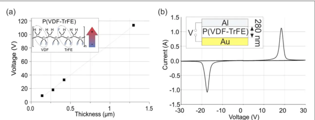
with 50μm thickness and 0.3 cm2 surface area. The simulation results of the model show a good match with the experimental data as shown infigure2. 3.2. Characterization of the P(VDF-TrFE) capacitor P(VDF-TrFE) (see the inset of figure3) is the most commonly used organic ferroelectric material with a typical remnant polarization of about 10μC cm−2 [40,41]. In order to polarize a P(VDF-TrFE) film an
electricfield should be applied across it. The minimum electricfield needed for the polarization of the P(VDF-TrFE) is called the coercive field. When the electric field applied across the P(VDF-TrFE) film, increases from zero, the electric dipoles start to align with the field. Close to the coercive field the polarization of the dipoles results in an electric current across thefilm which peaks at the coercivefield and decreases to zero after all the dipoles are aligned. To estimate the coercive field, ferroelectric capacitors with different thicknesses are fabricated and the polarization voltage
is measured. Figure3(a) shows the polarization voltage of ferroelectric capacitors versus thickness. The coer-civefield is calculated from the slope of the line to be approximately 91 MV m−1 which is in good agree-ment with previously reported values[40]. The I–V characteristics of a P(VDF-TrFE) capacitor with an Au electrode and an Al electrode sandwiching a 280 nm thick polymer ferroelectric layer is shown in figure3(b).
Figure 1.(a) Schematic structure of the EP cell. (b) Measurement setup used to record the color of the cell. (c) The current, the applied voltage and the color of the cell plotted versus time(in the color axis zero corresponds to the blue state and one corresponds to the white state of the cell).
Figure 2.(a) The Nyquist plot of the cell impedance (circles) and the model (solid line). The inset of the left side image shows the electrical equivalent circuit used to model the cell.(b) The amplitude and phase of the cell impedance (circles) and the model (solid line).
4
3.3. The integrated device
As discussed before, an electrophoretic display has a linear capacitive current–voltage relation and the voltage needed for switching of the color depends on the cell thickness. A nonlinear element is needed to provide a threshold voltage of the cell. Here the ferroelectric capacitor is used as a passive nonlinear element to set the threshold voltage for switching of the display color. The structure of the display cell integrated with the ferroelectric capacitance is sche-matically shown infigure4(a1). However, for all of the measurements and characterizations, the setup in figure4(a2) is actually used. This configuration is in fact the exact equivalent of the integrated cell.
In order to switch the polarization of the ferro-electric capacitor an equal amount of compensation charge should be available on the electrodes otherwise the ferroelectric layer depolarizes. As shown in figure1(c), the color of the EP cell with 50 μm thick-ness is completely switched at±5 V. At a steady state condition, under electric bias, the surface charge on the electrodes equals the product of C and V, where C
is the sum of Cdland Cg. For a cell biased at 5 V with
1 cm2surface area this calculation gives a value about 330 nC. Therefore, in order to provide the compensa-tion charge for the polarizacompensa-tion of the ferroelectric (10 μC cm−2) the surface area of the EP cell must be at
least 30 times larger than that of the ferroelectric[34]. However, in reality the true equivalent circuit of the EP cell appears more complicated since the cell cannot be perfectly modeled using ideal capacitors and resistors. Therefore, an optimum surface area ratio for the actual physical device to work properly might be larger or smaller than the calculated value. Never-theless, the calculation can be used as a starting point to balance the areas of the top transparent electrode and the area of the ferroelectric device. The calculation indicates that the surface charge per unit area that the electrophoretic ink can provide is about two orders of magnitude less than that of the ferroelectric surface. In order tofind the optimum surface area ratio between the ferroelectric capacitor and the cell(AFE/AEP), three
different surface area ratios, 1/30, 1/125 and 1/500 were tested. Among these three AFE/AEPratios, 1/125
Figure 3.(a) The polarization voltage of the P(VDF-TrFE) versus the film thickness. The inset shows the molecular structure of P(VDF-TrFE). (b) The 10 V s−1I–V curve of a 280 nm P(VDF-TrFE) capacitor in the inset with the coercive voltage of about 16 V.
Figure 4.(a1) The structure of the designed electrophoretic cell integrated with the ferroelectric capacitor. (a2) The equivalent circuit of the integrated cell that is used for the measurements before polarizing.(a3), (a4) The measurement circuit when the ferroelectric is positively and negatively polarized.(b) The current and the color of the device (with a 280 nm thick ferroelectric) versus the applied voltage(in the color axis zero corresponds to the blue state and one corresponds to the white state of the cell). (c) Color and the current of the setup plotted versus time.
yields the best result, suggesting a reasonable error in our calculations. Figure4(b) shows the current of the device versus the applied voltage while the display color is recorded using the setup shown infigure1(b) for a ferroelectric capacitance with 1 mm2surface area and 280 nm thickness coupled to a display cell with 1.25 cm2surface area. Starting from 0 V when the fer-roelectric is not polarized, the current of the device remains low until the coercivefield is reached. As soon as the voltage drop on the ferroelectric capacitor reaches the coercive voltage, the ferroelectric is polar-ized and the charge displacement currentflows in the device allowing the charged particles in the display to move and change the display color (figure 4 (a3)). Once the ferroelectric is polarized, the current drops, and the ferroelectric layer remains polarized until the coercive voltage with the opposite polarity is applied (figure4(a4)). The color of the display switches simul-taneously with the current peak in the I–V curve, which means that the ferroelectric polarizes. The amplitude of the voltage needed to switch the color of the electrophoretic cell with the ferroelectric capacitor (30 V as shown in figure4(b)) is higher compared to the cell without the ferroelectric capacitor (5 V as shown infigure1(c)). However the switching voltage of the integrated device is mainly dictated by the thick-ness of the ferroelectric layer and therefor by lowering the thickness of the ferroelectric layer lower opera-tional voltages can be attained.
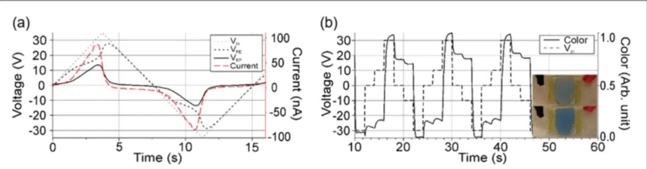
The capacitance of the P(VDF-TrFE) is field dependent and has a maximum at the coercivefield. This trend can be observed in the current and voltage profile of the device in figure5(a), which shows the current and the voltage drop on the ferroelectric capa-citance and the EP cell separately. The current peak is an identification of the switching of the ferroelectric polarization. Since the voltage is proportional to the inverse of the capacitance, a large portion of the input voltage drops over the ferroelectric capacitance before and after the polarization when the capacitance is low. During the polarization, the voltage drop on the EP cell has a peak and the input voltage is divided almost equally between the EP cell and the FE capacitor. Figure5(b) shows the color of the EP cell when a pulse
train with levels below and above the coercive voltage is applied. The color of the display remains almost constant as long as the voltage drop on the ferro-electric is below the coercive voltage. Once the coer-civefield is applied the color changes.
In case the surface area ratio AFE/AEPis larger than
the optimum value, the display cannot provide enough surface charge to compensate for the remnant polarization of the ferroelectric. To exemplify this, the electrical and the color profile of an EP cell with 1.25 cm2surface area connected to a 4 mm2 P(VDF-TrFE) capacitor (AFE/AEP≈1/30) is shown in figure
S1 is available online at stacks.iop.org/FPE/4/ 035004/mmedia. Increasing the surface area of the ferroelectric cell results in higher ferroelectric capaci-tance and leakage current. Consequently, the voltage drop on the EP cell is higher and the leakage current of the ferroelectric allows the charged particles in the dis-play to move and the disdis-play color switches. However, the voltage drop on the ferroelectric does not reach the coercive voltage and the ferroelectric does not polarize.
A small surface area ratio AFE/AEP, has an opposite
effect in that the ferroelectric capacitance polarizes completely, but the color of the EP cell does not com-pletely switch. Figure S2 shows the electrical and the color profile of an EP cell with 1.25 cm2surface area connected to a 0.25 mm2 P(VDF-TrFE) capacitor (AFE/AEP≈1/500). In this case, there are more than
enough surface charges available in the display to com-pensate for the remnant polarization of the ferro-electric. The capacitance and the current leakage of the ferroelectric are lower resulting in a larger portion of the input voltage to fall over the ferroelectric. There-fore, once the coercivefield is applied, the ferroelectric completely polarizes. However, a smaller ferroelectric surface area results in a smaller charge displacement current. The current is not high enough to allow all the charged particles to move to the electrode with oppo-site polarity and the display cannot switch the color completely. This effect is clearly illustrated infigure S2(b) showing the EP cell color versus time when a voltage sweep is repeatedly applied. The color levels in
Figure 5.(a) The current, input voltage and the voltage drop on the EP cell and on the ferroelectric capacitor versus time. (b) The color of the cell while the input pulse train with amplitudes higher and lower than the coercive voltage of ferroelectric are applied(in the color axis zero corresponds to the blue state and one corresponds to the white state of the cell). The inset shows the two-color states of the EP cell.
6
different cycles are not stable since the current is not enough to allow all of the charged particles to move.
4. Conclusion
In summary, we present a simple approach to define a threshold voltage for an electrophoretic display cell by depositing a layer of the organic ferroelectric P (VDF-TrFE) on one of the electrodes of the cell. As a first step, the electrophoretic ink is characterized using impedance spectroscopy and modeled with an elec-trical equivalent circuit to estimate the capacitance and consequently the surface charge density of the display cell. The surface area ratio between the ferro-electric and the display cell is balanced so that the electrophoretic ink can provide enough surface charge to polarize the ferroelectric thinfilm. The ferroelectric displacement current is just enough for the display to fully switch the color. We have used the electrical equivalent of nonlinear EP cell structure to show that a threshold voltage is added to the I–V characteristic of the electrophoretic cell by addition of a ferroelectric layer, meaning that the color of the cell does not change unless the input voltage overcomes the coer-cive voltage of the ferroelectric layer. This nonlinearity in the device characteristics makes the reported device suitable for passive addressing, which is a simple and low-cost alternative to the active addressing configura-tion commonly used for EPIDs.
Acknowledgments
This research was partially supported by the Advanced Functional Materials Center at Linköping University and the Önnesjö Foundation. The authors thank the Knut and Alice Wallenberg Foundation(Power paper project, scholar) and the Swedish Foundation for Strategic Research (Synergy project) for financial support.
We would like to thank ARKEMA for the blocbuilder-SG1® and the Aquitaine region for the funding. The authors thank Arkema for the CIFRE PhD fellowship allocated to DM. This work was per-formed within the framework of the Equipex ELOR-PrintTec ANR-10EQPX-28-01 and the LabEx AMADEUS ANR-10-LABEX0042-AMADEUS with the help of the French state Initiative d’Excellence IdEx ANR-10-IDEX-003-02 and the LCPO/Arkema INDUSTRIAL CHAIR ‘HOMERIC’ ANR-13CHIN-0002-01.
ORCID iDs
Negar Sani https://orcid.org/0000-0002-6157-4767
Daniel Simon https: //orcid.org/0000-0002-2799-3490
References
[1] Andersson Ersman P, Kawahara J and Berggren M 2013 Printed passive matrix addressed electrochromic displays Org. Electron.14 3371–8
[2] Tehrani P et al 2009 Improving the contrast of all-printed electrochromic polymer on paper displays J. Mater. Chem.19 1799–802
[3] Gelinck G H et al 2004 Flexible active-matrix displays and shift registers based on solution-processed organic transistors Nat. Mater.3 106–9
[4] Liang J, Jiang C and Wu W 2019 Toward fiber-, paper-, and foam-basedflexible solid-state supercapacitors: electrode materials and device designs Nanoscale11 7041–61
[5] Liu L, Feng Y and Wu W 2019 Recent progress in printed flexible solid-state supercapacitors for portable and wearable energy storage J. Power Sources410-411 69–77
[6] Wu W 2017 Inorganic nanomaterials for printed electronics: a review Nanoscale9 7342–72
[7] Wu W 2019 Stretchable electronics: functional materials, fabrication strategies and applications Sci. Technol. Adv. Mater.
20 187–224
[8] Heikenfeld J et al 2011 Review paper: a critical review of the present and future prospects for electronic paper J. Soc. Inf. Disp.19 129–56
[9] Comiskey B et al 1998 An electrophoretic ink for all-printed reflective electronic displays Nature394 253–5
[10] Chen Y et al 2003 Electronic paper: flexible active-matrix electronic ink display Nature423 136–136
[11] Kawamoto H 2002 The history of liquid-crystal displays Proc. IEEE90 460–500
[12] Henzen A et al 2004 Development of active-matrix electronic-ink displays for handheld devices J. Soc. Inf. Disp.12 17–22
[13] Burns S E et al 2005 A scalable manufacturing process for flexible active-matrix e-paper displays J. Soc. Inf. Disp.13 583–6
[14] Gelinck G H et al 2004 Flexible active-matrix displays and shift registers based on solution-processed organic transistors Nat. Mater.3 106–10
[15] Kawase T et al 2003 Inkjet printing of polymer thin film transistors Thin Solid Films438–439 279–87
[16] Edzer H et al 2006 Flexible electronic-paper active-matrix displays J. Soc. Inf. Disp.14 729–33
[17] Park J and Jacobson J M All printed bistable reflective displays: printable electrophoretic ink and all printed Metal-Insulator-Metal Diodes Materials Research Society Symp.—Proc.. 1998 [18] Bert T et al Passive matrix addressing of electrophoretic image
display 22nd Int. Display Research Conf. (IDRC 2002/ Eurodisplay 2002). 2002. Society for Information Display (SID) [19] Lilja K E et al 2010 Printed organic diode backplane for matrix
addressing an electrophoretic display Thin Solid Films518 4385–9
[20] Scott J F and Araujo C A P D 1989 Ferroelectric memories Science246 1400–5
[21] Setter N et al 2006 Ferroelectric thin films: review of materials, properties, and applications J. Appl. Phys.100 051606
[22] Yagi T, Tatemoto M and Sako J-I 1980 Transition behavior and dielectric properties in trifluoroethylene and vinylidene fluoride copolymers Polym. J.12 209–23
[23] Yamauchi N 1986 metal-insulator-semiconductor (mis) device using a ferroelectric polymer thinfilm in the gate insulator Japan. J. Appl. Phys. 125 590–4
[24] Ling Q-D et al 2008 Polymer electronic memories: materials, devices and mechanisms Prog. Polym. Sci.33 917–78
[25] Mai M et al 2015 Ferroelectric polymer thin films for organic electronics J. Nanomater.2015 14
[26] Xu H et al 2007 Ferroelectric and switching behavior of poly (vinylidene fluoride-trifluoroethylene) copolymer ultrathin films with polypyrrole interface Appl. Phys. Lett.90 092903
[27] Li X et al 2013 P(VDF-TrFE) ferroelectric nanotube array for high energy density capacitor applications Phys. Chem. Chem. Phys.15 515–20
[28] Fabiano S, Crispin X and Berggren M 2014 Ferroelectric polarization induces electric double layer bistability in electrolyte-gatedfield-effect transistors ACS Appl. Mater. Interfaces6 438–42
[29] Zheng Y et al 2009 Gate-controlled nonvolatile graphene-ferroelectric memory Appl. Phys. Lett.94 163505
[30] Sekitani T et al 2009 Printed nonvolatile memory for a sheet-type communication system Electron Devices, IEEE Trans.56 1027–35
[31] Asadi K et al 2008 Organic non-volatile memories from ferroelectric phase-separated blends Nat. Mater.7 547–50
[32] Naber R C G et al 2010 Organic nonvolatile memory devices based on ferroelectricity Adv. Mater.22 933–45
[33] Asadi K, Blom P W M and Leeuw D M D 2011 The MEMOLED: active addressing with passive driving Adv. Mater.23 865–8
[34] Fabiano S et al 2017 Ferroelectric polarization induces electronic nonlinearity in ion-doped conducting polymers. Sci. Adv.3 e1700345
[35] Charbonnier A et al 2013 Synthesis of functional polymer particles by dispersion polymerization in organic media: a tool toward stable electrophoretic inks J. Polym. Sci. A51 4608–17
[36] Stöber W, Fink A and Bohn E 1968 Controlled growth of monodisperse silica spheres in the micron size range J. Colloid Interface Sci.26 62–9
[37] Noel A et al 2018 Tridodecylamine, an efficient charge control agent in non-polar media for electrophoretic inks application Appl. Surf. Sci.428 870–6
[38] Kawahara J et al 2012 Improving the color switch contrast in PEDOT:PSS-based electrochromic displays Org. Electron.13 469–74
[39] Yezer B A et al 2015 Use of electrochemical impedance spectroscopy to determine double-layer capacitance in doped nonpolar liquids J. Colloid Interface Sci.449 2–12
[40] Kliem H and Tadros-Morgane R 2005 Extrinsic versus intrinsic ferroelectric switching: experimental investigations using ultra-thin PVDF Langmuir–Blodgett films J. Phys. D: Appl. Phys.38 1860
[41] Ferris R J et al 2013 Electric double layer formed by polarized ferroelectric thinfilms Acs Appl. Mater. Interfaces5 2610–7
8