V¨aster˚as, Sweden
Thesis for the Degree of Bachelor of Science in Engineering -Computer Network Engineering 15.0 credits
SOFT MIGRATION FROM
TRADITIONAL TO SOFTWARE
DEFINED NETWORKS
Authors:Darian Mohammed
dmd16002@student.mdh.seLiver Toma
lta16001@student.mdh.se Examiner: Moris Behnam moris.behnam@mdh.se Supervisor: Mohammed Ashjaei mohammed.ashjaei@mdh.se Svetlana Girs svetlana.girs@mdh.se June 18, 2019Abstract
The concept of Software Defined Networking (SDN) may be a way to face the fast growing computer network infrastructure with its demands and requirements. The concept is at-tracting the interest of enterprises to expand their respective network infrastructures, but one has to consider the impacts of migrating from an existing network infrastructure to an SDN network. One way that could minimize the impacts is to proceed a soft migration from a traditional IP network to SDN, creating what is so called a heterogeneous network. Instead of fully replacing the network infrastructure and face the impacts of it, the idea of the soft migration is to replace a part of it with an environment of SDN and examine the performance of it. This thesis work will analyse the performance of a network consisting of a traditional IP network combined with SDN. It is essential during this work to identify the differences in performance when having a heterogeneous network in comparison with having a dedicated traditional IP network. Therefore, the questions that will be addressed during this thesis work is to examine how such a heterogeneous network can be designed and measure the performance of it in terms of throughput, jitter and packet losses. By the method of experimentation and the studying of related works of the SDN fundamentals, we hope to achieve our goals with this thesis work, to give us and the reader a clearer insight.
Acknowledgements
This thesis for the degree of Bachelor of Science in Engineering - Computer Network En-gineering 15.0 credits is written by Darian Mohammed and Liver Toma in M¨alardalen University.
Due to this thesis work, we have gained an insight into a big part of the network industry. We have learned that there will be obstacles that we have to overcome in order to better ourselves. By completing this thesis, we have taken our responsibility and structured our time, therefore we want to thank each other for the support and the encouragement we have given each other during the past three years and specially during this thesis work. We would like to express our very great appreciation to our supervisors, Mohammed Ash-jaei & Svetlana Girs and examiner, Moris Behnam for taking their time and helping us form this work, the patient guidance given by them has been invaluable and we will always be thankful for that.
We would also like to extend our thanks to all the teachers in the Computer Network Engineering program, School of Innovation, Design and Engineering.
Finally we would like to give a special thanks to our friends and families for always being there and supporting us throughout the entire journey.
Table of Contents
1 Introduction 1
1.1 Problem Formulation . . . 1
2 Background 2 2.1 Control and Data Plane . . . 2
2.2 Types of Communication . . . 2
2.2.1 Connection-Oriented Communication . . . 2
2.2.2 Connectionless Communication . . . 3
2.3 Transmission Protocols . . . 3
2.3.1 Transmission Control Protocol . . . 3
2.3.2 User Datagram Protocol . . . 4
2.4 Network Performance . . . 4
2.4.1 iPerf3 . . . 4
2.5 Traditional IP Networks . . . 5
2.5.1 Data Link Layer . . . 6
2.5.2 Network Layer . . . 6
2.5.3 Traditional Switch . . . 6
2.6 Software Defined Networking . . . 7
2.6.1 SDN Controller . . . 7
2.6.2 The Southbound and Northbound Interface . . . 8
2.6.3 OpenFlow Switch . . . 9
2.6.4 OpenFlow Protocol . . . 10
2.7 VirtualBox . . . 10
2.8 Raspberry PI . . . 10
3 Related Work 11 3.1 Constructing a Heterogeneous Network . . . 11
3.1.1 OSPF Based SDN . . . 12
3.1.2 MPLS Based SDN . . . 13
4 Method 14 5 Ethical and Societal Considerations 15 6 Design and Implementation 16 6.1 Scenarios . . . 16
6.1.1 Scenario 1: The Heterogeneous Network . . . 16
6.1.2 Scenario 2: The Traditional Network . . . 17
6.2 Testing Program . . . 18
6.2.1 iPerf3 . . . 18
6.2.2 Python Codes . . . 18
7 Results 19 7.1 Scenario 1: The Heterogeneous Network . . . 19
7.2 Scenario 2: The Traditional Network . . . 25
8 Discussion 29 8.1 Design choice . . . 29 8.1.1 Scalability . . . 29 8.2 Performance Analysis . . . 30 9 Conclusions 32 10 Future Works 33 References 36
List of Figures
1 TCP Communication . . . 3
2 Cisco Hierarchical Network Model . . . 5
3 Traditional Switch: Cisco Catalyst 2960 . . . 6
4 Control and Data Plane Separation . . . 7
5 SDN Architecture . . . 8
6 OpenFlow Switch: Zodiac FX . . . 9
7 SDN & OSPF Topology . . . 12
8 SDN & MPLS Topology . . . 13
9 The Waterfall Methodology . . . 14
10 Scenario 1: The heterogeneous network . . . 17
11 Scenario 2: The traditional network . . . 17
12 Delay Early Packets . . . 19
13 TCP Throughput . . . 20
14 TCP Retransmission . . . 21
15 UDP Throughput . . . 22
16 Jitter . . . 23
17 UDP Packet loss . . . 24
18 TCP Throughput . . . 25
19 UDP Throughput . . . 26
20 Jitter . . . 27
21 UDP Packet Loss . . . 28
List of Tables
1 Technical Documentation . . . 162 Scenario 1: Values for delay early packets . . . 19
3 Scenario 1: Values for TCP throughput . . . 20
4 Scenario 1: Values for TCP retransmissions . . . 21
5 Scenario 1: Values for UDP throughput . . . 22
6 Scenario 1: Values for jitter . . . 23
7 Scenario 1: Values for UDP packet loss . . . 24
8 Scenario 2: Values for TCP throughput . . . 25
9 Scenario 2: Values for UDP throughput . . . 26
10 Scenario 2: Values for jitter . . . 27
1
Introduction
In the digitized world of today, computer networks are growing inevitably. The fast grow-ing infrastructure is demandgrow-ing the traditional networks to face more complex require-ments. To solve the upcoming problems, a new concept, also known as Software Defined networking (SDN), was introduced [1]. The concept of a centralized controller has been going along since the beginning of the OpenFlow project and the term SDN was born to describe the concept of utilizing a logical controller. Today, the concept is used to de-scribe more flexible and scalable network solution where SDN is considered the innovative method for design, implementation and network management.
Considering the impact that SDN makes when migrating from a traditional IP network infrastructure, new challenges such as managing new equipment, teaching current staff and new routines have been introduced for companies. One way to minimize the impact is to proceed a soft migration from the traditional IP network to SDN, creating a heterogeneous network.
1.1 Problem Formulation
The fast growth in the SDN development and community are attracting the interests of enterprises to expand and develop their respective network infrastructure [2]. One has to keep in mind that this procedure is not as easy as it seems. Migrating from traditional IP networks to the SDN field may be a step forward, but a new network infrastructure comes with several disadvantages such as:
1. The network needs to be reconfigured which can prevent the enterprise to manage their business for an indeterminate amount of time.
2. Provide expertise and knowledge to the staff so that they can manage the new infrastructure.
3. A new network also requires new tools such as monitoring, administration and main-tenance.
Our main goal during this thesis is to reach for a better scenario where an existing network infrastructure is successively aiming towards new and more efficient, scalable and central-ized network infrastructure such as SDN. Instead of initiating large projects to replace the network infrastructure, our idea is to successively replace parts of the network and create what is now called a heterogeneous network. Thus, in this thesis we consider a network consisting of a traditional IP part and another part of a software defined network. The idea is to prevent the process of replacing the network infrastructure with new equipment at once but instead moving slowly towards the migration from the traditional network to the SDN. The main focus of this thesis is to implement the heterogeneous network and to evaluate the network performance on a set of parameters. It is essential for us to identify the differences and measure the network performance that will differ when having a het-erogeneous network and having a dedicated traditional network. Therefor, the following questions will be addressed during this thesis work:
• How such a heterogeneous network can be designed?
• How will the heterogeneous network perform in terms of throughput, jitter and packet loss?
2
Background
This section presents the fundamental information about networking and software defined networking.
2.1 Control and Data Plane
There are three types of network planes, these are the control, data and management plane with each one of them responsible for different main tasks [3]. The following section will present the fundamentals for the control and data plane which is the essentials for this thesis work.
Control Plane
Routers and multi-layer switches have the task of detecting and forming neighborhoods using routing protocols. The forming of neighborhoods happens in the control plane [4]. The control plane in a network device manages the network topology and other network devices it knows. Control plane also handles the Forwarding Information Base (FIB) and Media Access Control (MAC) tables. The FIB table is used to do look-ups and decides where packets will be forwarded while the MAC table stores the unique layer 2 addresses. A network device can check where to send packets using the tables in the control plane. Data Plane
Data plane, also referred to as the forwarding plane, is the plane responsible for delivering data packets to the end devices [4]. It is composed of networking equipment such as switches and routers specialized and implemented for packet forwarding. Depending on the routing decisions the control plane makes, the data plane is able to performs its tasks. The data plane handles packets that are not for the device itself, but which must be forwarded to other devices.
2.2 Types of Communication
In computer networking, one could find two distinct methods used in network cation for transmitting data, including connection oriented and connectionless communi-cation [5]. Depending on the design and requirements of the system, the choice of com-munication method can be crucial for the system to work properly since each individual communication type manages everything from establishment to exchanging transmissions with a different approach. Depending on the choice of communication system, there are suitable protocols that can be found to fulfill the main design and purpose of each system. 2.2.1 Connection-Oriented Communication
In connection-oriented communication, a sender and a receiver should establish a com-munication channel before they can transmit information. [5]. In this type of communi-cation, the sender and receiver can dynamically control the transmission data rate. In a connection-oriented communication, authentication is needed and every exchanged packet between the transmitter and receiver is inspected. If some kind of error is detected or in the worst case, that the destination did not receive the packet, errors are corrected or message is sent again. Connection-oriented communication is considered as reliable com-munication but can experience high delay during comcom-munication due to the time it takes to establish a communication channel.
2.2.2 Connectionless Communication
In a connectionless communication, a sender and a receiver can transmit information without any early connection establishment [5]. The necessary information is added to the data such as source and destination, but there are no guarantees that the destination has received the information. In this type of communication, there can be limits due to the physical medium and layer protocol when sending data at a specific data rate. In a connectionless communication, no authentication is needed and packets are sent without taking into account whether the destination has received the packet correctly or received the message at all.
2.3 Transmission Protocols
Based on section 2.2, the requirements needed to be fulfilled for a connection-oriented and connectionless communication, there are a variety of transmission protocols that can be used during the design of such a communication. The Transmission Control Protocol (TCP) and the User Datagram Protocol (UDP) is so called transmission protocols and the most well-known amongst them all [6,7]. These two protocols manages transmissions between nodes in a computer network, with each one of them approaching it differently where you find TCP more useful in a connection-oriented communication whilst UDP is a better design choice for connectionless communication.
2.3.1 Transmission Control Protocol
The Transmission Control Protocol is a connection-oriented, end-to-end reliable protocol that provides reliable communication between a pair of nodes [8]. Applications and hosts can create a connection such as a virtual circuit where they can exchange streams of data. The sender and receiver exchange their data in form of packets also known as segments in TCP, the size of these segments is controlled by the TCP. The transmission in TCP is reliable due to the smart use of sequences and acknowledgments. Each sequence is assigned a sequence number and for every sent segment TCP expects an acknowledgment before sending the next one. TCP creates a copy of the sent segment and if no acknowledgment is received before a fixed amount of time, the segment is resent again. Figure1demonstrates a TCP communication after establishment between two hosts. The figure illustrates the sequences sent between the hosts and the respective acknowledgement of each sequence.
HOST A HOST B
Initial Sequence Number for host A
Initial Sequence Number for host B
SYN (SEQ = X)
SYN (SEQ = Y
, ACK = X + 1)
SYN (SEQ = X + 1, ACK = Y + 1)
2.3.2 User Datagram Protocol
The User Datagram Protocol provides unreliable, minimum and best effort packet delivery and is referred to as a connectionless communication protocol [9]. While TCP supports authentication, connection establishment, error and flow control, no such function and mechanisms are supported in UDP. It differs from TCP in the sense that no virtual circuit is required to be established before transmitting data and is the main reason why UDP is considered as a connectionless protocol. The protocol is used mainly for establishing low latency and loss tolerating connections and sends packets also known as datagrams in UDP, which is considered as a best effort mode. Since UDP is not in need of any connection setup and re-transmission of lost packets, the transmission of data comes at a low cost at lower delay compated to TCP. This makes UDP an excellent choice for delay sensitive applications.
2.4 Network Performance
Network performance refers to the quality of service evaluation. There are several pa-rameters that are important to measure in a network, including bandwidth, throughput, delay, jitter and packet loss.
Throughput Throughput is used to measure a device over a specific period of time. Measuring throughput in a network shows the amount of data trans-ferred between two devices in a period of time. In this thesis work, throughput is used to measure the network communications, but through-put can also be used to measure processors and memory.
Delay Delay is the amount of time it takes for a packet to traverse from source to destination.
Jitter Jitter is the variation in delay.
Packet Loss Packet loss is when packets fails to reach their intended destination. 2.4.1 iPerf3
iPerf3 is a tool for measuring the maximum achievable bandwidth for networks [10]. The tool is developed by ESnet/Lawrence Berkeley National Laboratory and is released under BSD license. iPerf3 supports traffic generation with several protocols (TCP, UDP and SCTP). It is used for collecting statics, such as jitter, packet loss and bandwidth. When running tests, iPerf3 allows users to change parameters, such as buffer size, bandwidth, parallel streams and the type of communication protocol.
2.5 Traditional IP Networks
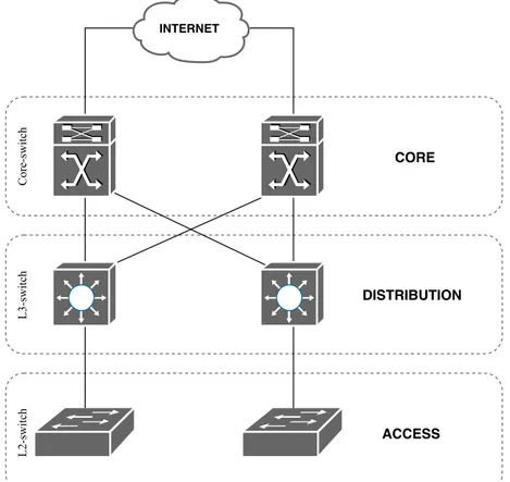
Traditional networks usually follow best practice methods [11]. Cisco Hierarchical network model is considered what is called the best practice when the design of the network is being planned. By using the hierarchical model the network gets divided into layers with the main aim of reducing the network complexity. A network build with the hierarchical model consists of three layers: Core, Distribution and Access, see Figure2.
CORE DISTRIBUTION ACCESS L2switch INTERNET Coreswitch L3switch
Figure 2: Cisco Hierarchical Network Model
Access The access layer manages users and workgroups access to the network. The access layer works with layer 2 devices such as switches and access points to provide connectivity between end users and the outer network. Distribution The distribution layer is the middle layer between core and access layers. The primary functions of the distribution layer is to route traffic between core and access layers. The distribution layer determines which route is the fastest for a requested service. This layer consists of routers and multilayer switches.
Core The core layer, also referred to as the network backbone, is in charge of connecting the three layers to a network. The core layer has the responsibility to transport heavy amount of data as fast as possible, thus the traffic that leaves and enters the three layered network is not filtered and verified in the backbone layer for the maximum data rate.
2.5.1 Data Link Layer
The Data Link layer is also referred to as Layer 2 in the Open System Interconnec-tion (OSI) model [5]. The data link layer offers a range of more complex functions for connection-oriented and connectionless communications compared to the other OSI lay-ers. The fundamentals for the data link layer is to establish communication between the entities and guarantee the data transfer between the nodes. It defines the access strategy when multiple nodes share a physical medium including data link and media access issues, based on MAC addresses. The MAC address is a unique hardware address found on every network device. At the data link layer, the network devices are able to communicate within the network, thus is the main function of the MAC addresses. At a more complex state, the data link layer can detect errors due to physical channels being exposed to interference and other distortions.
2.5.2 Network Layer
The network layer also known as the Layer 3 in the OSI model, is responsible for routing of data from one network to another and controlling the subnets [5]. The layer is providing transfer of variable length network packets through one or more networks. Some well known protocols as the Enhanced Interior Gateway Routing Protocol (EIGRP), Open Shortest Path First (OSPF) and Internet Control Message Protocol (ICMP), all operates at the network layer. The main function of the mentioned protocols, and other protocols in the network layer, is to select the best path and verify connectivity from source to destination and sending data along that path. This is done based on the Internet Protocol (IP) addresses and implicates to the main function of the network layer.
2.5.3 Traditional Switch
A traditional switch is used for connecting devices together in a network and an effective approach to add extra ports to an existing network [12]. Several Ethernet ports on the switch can be used for connecting various types of network devices such as different com-puter groups localized in the same or different geographical areas. Based on the type of the switch, packets are forwarded differently. A layer 2 switch forwards packets based on the MAC address whilst a layer 3 switch, also called multilayer switch, forwards packets based on MAC and IP addresses.
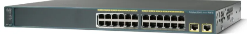
The traditional switch used in this thesis work is the Cisco Catalyst 2960, shown in Figure
3. Catalyst 2960 series switches, developed by Cisco, are the leading Layer 2 edge switch [13]. It consists of 24 x 10/100 Mb and 2 x 10/100/1000 Ethernet Ports.
Figure 3: Traditional Switch: Cisco Catalyst 29601
1Cisco Catalyst 2960-24TT-L Switch. URL: https://www.cisco.com/c/en/us/support/switches/catalyst-2960-24tt-l-switch/model.html Accessed: 2019-03-14
2.6 Software Defined Networking
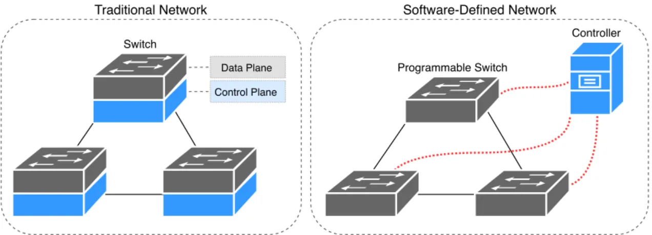
Software Defined Networking (SDN) is an architecture for networks that aims to simplify the management and administration [14]. By separating the control plane and the data plane on the network devices, SDN makes a more centralized network by moving the control functions to the controller, as shown in Figure 4. SDN provides a programmable access and becomes more efficient for increasing complexity and network growth. SDN is not only used for configuration of the network, SDN applications makes it possible for users to use Quality of Service (QoS), traffic engineering, security, routing, load balancing, virtualization, monitoring and in the future most likely new innovations.
Switch Controller Data Plane
Control Plane
Programmable Switch
Traditional Network Software-Defined Network
Figure 4: Control and Data Plane Separation
2.6.1 SDN Controller
SDN controller is the core of an SDN architecture. The SDN controller is the central point of the SDN network, which means that all communication between applications and the network is done with the help of the controller [15]. The controller uses several protocols and decides where packets should be sent. The traffic is directed according to policies in the flow table, set by a network administrator. A number of the most popular Open Source SDN controllers in use today are:
Floodlight Amongst the many SDN controllers, Floodlight is one of the most pop-ular OpenFlow controllers. Floodlight is an open source and Apache li-censed java based OpenFlow controller invented by Big Switch Networks [16]. Floodlight supports a broad range of virtual and physical Open-Flow switches and can handle mixed-OpenOpen-Flow and non-OpenOpen-Flow net-works.
Ryu Ryu is a component-based and open source SDN controller written in Python [17,18]. Ryu is supported by Nippon Telegraph and Telephone Corporation (NTT). Ryu integrates with OpenStack and has support for OpenFlow. It has a well defined API, making it easier for network administrators to create and manage the network and applications.
OpenDaylight OpenDaylight (ODL) is an Open Source SDN controller by Linux Foun-dation Collaborative Community [15]. ODL combines open community developers and open source code. ODL can be a core component in the SDN network. ODL reduces complexity and extends the lifetime of the existing infrastructure. ODL has a clear focus on network programma-bility. ODL focuses on data center networks.
ONOS Open Network Operating System (ONOS) is another Open Source project by The Linux Foundation [19]. ONOS’s goal is to create an operat-ing system that is scalable, has high performance and high availability. ONOS is used for service provider networks.
2.6.2 The Southbound and Northbound Interface
For the SDN controller to be able to communicate with the network devices, the South-bound Interface (SBI) is used [20]. A SBI includes a protocol, usually OpenFlow protocol, to enable communication between the SDN controller and the network devices. The SBI also includes an Application Programming Interface (API). With the API, an application can exchange data with another application. Therefore, the SBI is used as an interface between the SDN controller and a network device, allowing the SDN controller to program the data plane forwarding tables.
The Northbound Interface (NBI) opens up the possibility for programs to collect network information from the SDN controller and use its functions, making the network more pro-grammable [20, pp. 768–769]. This makes room for automation and the use of third-party applications. Figure5 shows the two mentioned communication interfaces in an SDN ar-chitecture. Data Plane Application Plane Control Plane Southbound Interface SDN Controller Northbound Interface
Application Application Application Application
2.6.3 OpenFlow Switch
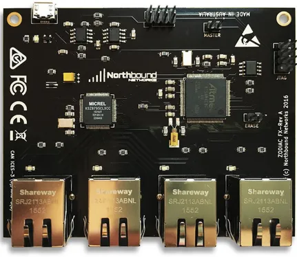
An OpenFlow switch is a unit that forwards packets in an SDN network [21]. An Open-Flow switch forwards packets by sending a request to the SDN controller and makes the forwarding to the correct destination based on the response. This means that the Open-Flow switch is not responsible for taking decisions about forwarding traffic, instead the SDN controller takes care of that. The OpenFlow switches consist of three parts: a flow table, a controller and the OpenFlow protocol. When a specificed entry for a network does not exist in the flow table, the switch requests the SDN controller for the correct infor-mation regarding the entry. The inforinfor-mation is stored for later use in the OpenFlow switch. The OpenFlow switch used in this thesis work is the Zodiac FX, see Figure6. The Zodiac FX, made by Northbound Networks, is a small OpenFlow switch designed to sit on your desk and not in a datacenter [22,23]. Zodiac FX is developed for researchers and devel-opers for SDN services. The Zodiac FX consists of four 10/100Mbs Ethernet Ports and is USB powered. The firmware is full Open Source and the configuration is both USB Serial and web-based. The size of the Zodiac FX switch is 100mm x 80mm and it weights 115 grams, making it one of the smallest OpenFlow switches. As default, the Zodiac FX is configurated to have one port directly connected to an SDN controller and the other three to clients.
Figure 6: OpenFlow Switch: Zodiac FX2
2Northbound Networks: Zodiac FX Overview. URL: https://northboundnetworks.com/products/zodiac-fx Accessed: 2019-03-14
2.6.4 OpenFlow Protocol
The communication between the controller and the OpenFlow switch is established with the OpenFlow protocol [24]. The protocol enables the controller to determine the path of a packet throughout the network consisting of switches. As mentioned, in the tradi-tional network each switch has its proprietary software that takes the decisions, with the OpenFlow the path decisions are centralized independently of the individual switch. The OpenFlow protocol is implemented and used on the control plane that is centralized on the SDN controller. The protocol makes sure that communication between the control plane and the data plane, which is distributed amongst the network units in the SDN network is established and verified.
2.7 VirtualBox
VirtualBox is a cross-platform virtualization application, meaning that it makes it possible to run, manage and host one or several operating systems virtually inside one physical device [25]. It was initially developed by Innotek GmbH, which later on was acquired by Oracle Corporation in 2010. VirtualBox runs on Windows, Linux, Macintosh, Solaris and FreeBSD.
2.8 Raspberry PI
The Raspberry PI is a low cost and small sized computer, capable of anything a desktop computer can do [26]. The Raspberry PI can interact with the outside world and is often used in projects. The idea of Raspberry PI began with teaching basic computer science to students. The first generation, called Raspberry PI 1 Model B, was releases in 2012 and had 256 Mb of RAM. Today there is several models with different CPUs and RAMs.
3
Related Work
The works in [27,28, 29] have addressed the possibility of having a hybrid of SDN and traditional IP networks. A study in [27] shows that a sudden and direct transition from the traditional IP network to a pure SDN network is unlikely to happen due to financial and business challenges. Instead of a purely SDN-network the study discussed the deploy-ment of hybrid SDN.
The work in [28] implemented two Autonomous Systems (AS), one as SDN and the other as IP. The IP AS was implemented to communicate with Border Gateway Protocol (BGP). The main task of the implementation was to create a mechanism for the SDN AS to com-municate with IP through the BGP network. The BGP protocol is very frequently used to share large amounts of data such as announcing large AS networks to neighbour ASes. Therefore the design of the two ASes created for this work, was to simulate a typical BGP topology where the IP part represents one AS and the SDN part another. The solution was implemented and evaluated for feasibility and performance and addresses the possi-bility of creating variety size of networks consisting of IP and SDN. Their implementation demo was evaluated using Mininet. The authors of [29] studied how a hybrid SDN which is basically a heterogeneous network with SDN as one part and another infrastructure as the other part, was fully working and verified combined with traditional IP networking based on distributed protocols. In another study [29] the authors show how hybrid SDNs can be used in different cases to soften the limitations of traditional IP networks.
The studies above give an insight into how a traditional IP network can be combined with SDN implemented in a heterogeneous network environment. Our goal is similar to the recent studies, to verify the link between an SDN network and a traditional IP net-work, however the recent studies did not present any measurements on how the topologies performed with respect to performance parameters such as throughput, delay and packet loss. These parameters are the main factors that will differ and separate our work from the recent studies found above. Further in this section we will review the state of the art in building a hybrid network architecture.
3.1 Constructing a Heterogeneous Network
One of the tasks declared in the problem formulation is to take a closer look at how a heterogeneous network can be designed. The purpose of this is to get a better understand-ing of different heterogeneous network topologies and their advantages and disadvantages. The study shows different heterogeneous topologies and their possibilities and limitations of building and verifying such a network. The following sections will present previously implemented heterogeneous SDN environments with a various type of equipment. The conclusions and results of the following works presented will be used to analyze and com-pare the decisions of our final design.
3.1.1 OSPF Based SDN
The authors of [30] analyze and test the possibility of building a heterogeneous network with SDN and legacy traditional routers running Open Shortest Path First (OSPF). The main goal of their migration from the traditional IP network to the heterogeneous network was to evaluate the received gain from the perspective of traffic engineering. The received gain in form of traffic engineering during this work is according to the authors to make the most out of the available network resources. It is to optimize the maximum link utilization by for example optimizing the routing for traffic delivery. The main performance metric used in this work and evaluated through algorithms is the so called path cost. In a dis-tributed protocol such as OSPF, this metric is used for deciding the best path from source to destination throughout the network, the path with lowest cost is preferred and priori-tized. The authors raised the problems occurring when migrating to a pure SDN-enabled network and the complexity of this task due to economical and technical challenges. The heterogeneous network was implemented by the use of SDN routers in a hybrid mode which were controlled by an external controller, see Figure7for full topology. The routers in hybrid mode were both SDN-enabled and OSPF-enabled which brings support for OSPF and arbitrarily use of the outgoing flows of the SDN routers through the central-ized controller is possible. The other legacy routers are operating in OSPF mode and only support the OSPF routing protocol. The specific type of equipment used during this implementation is unclear, but shows a possible topology to use with traditional units combined with SDN as our main topology during this work. According to the authors of the paper, migrating from the traditional IP network to the hybrid SDN & OSPF is a practical and significant way of gaining benefits from the perspective of traffic engineering.
SDN Controller Legacy Router SDN Router
3.1.2 MPLS Based SDN
The author of [31] examined how to combine SDN with Multiprotocol Label Switching (MPLS) in a switched environment. The main goal of the work was to use the standard MPLS data plane combined with a control plane, based on OpenFlow for their hybrid model. The network topology used, see Figure8, consist of an SDN controller, SDN com-patible switches and non-SDN switches. All the units used in the paper support MPLS and Spanning Tree Protocol (STP). OpenFlow was used to push MPLS entries into the SDN switches whereas it uses Open vSwitch Database Management (OVSDB) protocol to control the legacy switches. The OpenFlow switch used during this implementation is a model named P F 5240, which is an SDN switch considered operating at high class with high standard with the support of a various amount of protocols such as STP, MPLS, OSPF and more. This medium sized network topology used during this work could pos-sibly reflect to our final design of topology for the performance and evaluation part.
SDN Controller
SDN Switch Legacy Switch OpenFlow OVSDB
4
Method
Since SDN is not an uncharted area, a reasonable amount of literature studies can be found for initiating the research phase about the essentials of SDN. The literature studies and related works will give us the ability to initiate and construct our design and im-plementation phase which will later lead to the evaluation of the final result. The main method of evaluating the system will be experimental, therefore throughout this thesis experimentation of the final system is of high importance since the goal is to collect the essential data from the heterogeneous network to draw the final conclusions for the eval-uation results. For the best possible outcome of our documentation of the work, the final thesis report should constantly be worked on from the beginning of the thesis until the final approach.
The search for literature studies and related works are done using Google Scholar, IEEEx-plore and M¨alardalen University database Primo ExLibris. The following keywords are: Heterogeneous network, SDN, Traditional network, SDN Controller, Hybrid SDN, SDN Transition, SDN migration.
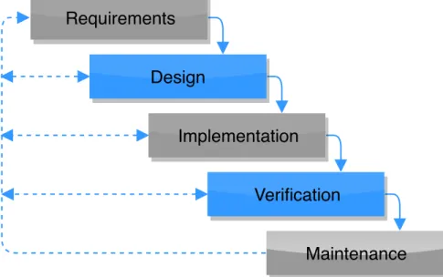
The engineering research method that will be used is the Waterfall method [32]. This method is well known and suitable methodology for this thesis since the phases is a direct representation of our main steps during the time plan. The Waterfall method is divided into five steps, see Figure9, and represents the beginning of a project till the end with the focus on system and software development. However, the M aintenance phase, will not be exploited during this thesis since the final goal is to measure and verify the heterogeneous network. One must also take into consideration that it can be crucial to fall back to already completed Waterfall phases due to the risk of a possible problem occurring at the present phase, which is why we have the reversed arrows in Figure9.
Requirements
Design
Implementation
Verification
Maintenance
5
Ethical and Societal Considerations
The goals of this thesis work is to build a heterogeneous network and to do measurements on the network. The experimental part will be build locally without any influence on Internet. No user information or related data will be saved. This thesis work will therefore not be a part of any ethical or social questions.
6
Design and Implementation
The goal of this thesis is to answer the questions in section1.1by creating two scenarios, one heterogeneous and one traditional. Both scenarios are set up and configured using the same set of equipment but in different topologies. To answer the questions, data needs to be collected from the network. The network measuring tool iPerf3 and Python codes will be used to collect data between clients. The following sections are used to describe how the experiments and measurements will be done. The following equipment are used in this thesis work:
• 1 Lenovo Ideapad laptop • 1 Cisco Catalyst 2960 switch • 1 Zodiac FX switch
• 2 Windows 10 clients
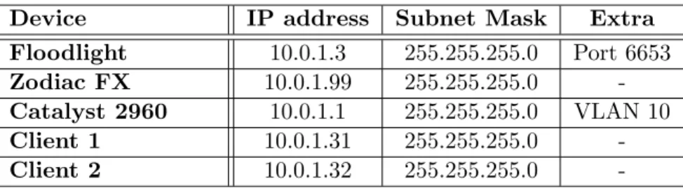
A virtual machine running Floodlight as the SDN controller is installed and configured on the Lenovo laptop with the help of VirtualBox. The virtual machine runs with one core, 2 GB of RAM, and have Ubuntu as operating system. Table 1 shows the configuration of IP addresses, subnet masks and additional information of each device operating in the network.
Device IP address Subnet Mask Extra
Floodlight 10.0.1.3 255.255.255.0 Port 6653
Zodiac FX 10.0.1.99 255.255.255.0
-Catalyst 2960 10.0.1.1 255.255.255.0 VLAN 10
Client 1 10.0.1.31 255.255.255.0
-Client 2 10.0.1.32 255.255.255.0
-Table 1: Technical Documentation
6.1 Scenarios
The following sections give an explanation of the scenarios, including how they are set up and how the experiments are done.
6.1.1 Scenario 1: The Heterogeneous Network
The first scenario, also referred to as the heterogeneous network is illustrated in Figure
10. The heterogeneous network consists of two parts, one traditional part and one SDN part. The traditional part consists of the Catalyst 2960 switch and a client. The SDN part, contrariwise consists of the Zodiac FX switch, the Lenovo laptop with Floodlight installed and configured as a virtual machine and a client.
It can be seen in Figure10, the traditional network is connected to the SDN network with the help of both switches. Port 1 on the traditional switch is connected to the client while port 24 is connected to port 2 on the OpenFlow switch. Port 1 on the Zodiac FX switch is connected to the client and port 4 is connected to Floodlight. Floodlight runs on port 6653.
Traditional Network SDN Network OpenFlow Switch Traditional Switch SDN Controller FloodLight Client Client
Figure 10: Scenario 1: The heterogeneous network
6.1.2 Scenario 2: The Traditional Network
The second scenario, also referred to as the traditional network is illustrated in Figure
11. To compare the collected data from scenario 1, scenario 2 was set up and configured. This illustration of a traditional network is a basic Local Area Network (LAN) consisting of a Cisco router, Cisco Catalyst 2960 switch and two clients. The clients are connected to port 1 and 2 on the traditional switch. The router interface is configured with the IP address of 10.0.1.1/24 and the clients are addressed with 10.0.1.31 and 10.0.1.32.
Traditional Network
Router
Traditional Switch
Client Client
6.2 Testing Program
In order to measure the performance we use, iPerf3 and Python codes. In this section, the measuring process are explained.
6.2.1 iPerf3
With a focus on throughput, jitter and packet loss Iperf3 was used to collect information for plotting on how the scenarios differ from each other.
Sender The sender, also referred to as the client can not send data if the server is not running. When the server is running, the client can initiate a connection and start exchangning data. When connected, the results are displayed on a new line based on an interval of how much data is transfered and for how long.
Receiver To start Iperf3 and collect data, the receiver also referred to as the server, needs to run. When starting the Iperf3 server, it listens to a port. When a client initiates a connection on that port, the client and the server can exchange data.
In this experiment, UDP and TCP was chosen as transport protocols. UDP for measuring throughput, jitter and packet loss while TCP is used for measuring throughput and packet retransmission. When measuring, the iPerf3 client sent 100 MB each second for a time period of 300 seconds for both TCP and UDP scenarios.
6.2.2 Python Codes
With a focus on delay, two Python codes were used to collect the delay on the first packet in the heterogeneous network. Both Python codes were found on a previous thesis work [33]. By restructuring the codes for this thesis the delay could be measured. In this section the codes are explained.
Sender The first code, named udp send.py, is the sender. The code start ups by making a time stamp, then sends a message and awaits for a response. By receiving the another timestamp is taken and the previous time is subtracted. In order to get one-way delay, the round-trip time is divided by two. The sender code, sends a specified number of packets and saves each delay in a file, where each line is the delay for each packet sent. Receiver The second code, named udp receive.py, is the code that acts like a server
and responds to received packets. This code replies with the same data as it receives.
In this experiment, the program were started by having the server running and then on the client side typing where to send data and how many packets to send. When the tests finishes running, the program prints out the amount time it was running and a makes a files with delay on each packet sent. The delay was measured in milliseconds (ms).
7
Results
This section will present the results achieved during the experimental phase on the final system. The results are presented in form of graphs and tables for each measurement performed. For a better cohesiveness this part will be divided into two headlines, where the results for the heterogeneous network will be represented first following by the traditional network scenario.
7.1 Scenario 1: The Heterogeneous Network
By looking at the early packets generated in the heterogeneous network, an isolated view of the delay from the SDN controller can be visualised. Figure12 represents the delay for each early packet transmitted, which can also be described as the amount of time it takes for the SDN controller to perform the first lookup and modification in the OpenFlow table to transmit the packet. Note that for each new packet, a new session is initiated to gen-erate a new value with the SDN controller included. Thus, the graph does not represent a burst of packets but instead the first packet for every new session. The round-trip time measured is divided by two, to get the one-way delay between the clients. The output from this test shows a significant high delay, this is due to OpenFlow switches making a request for forwarding directions to the SDN controller every time a new packet arrives which is not necessarily done when the flow is added to the table and packets are recog-nized. Table 2 presents the minimum, average and the maximum time in ms achieved during this experiment.
0 500 1000 1500 2000 2500 1 2 3 4 5 6 7 8 9 10 Delay (ms) Packet number Delay Early Packets
Figure 12: Delay Early Packets
Min: 1800 ms
Average: 2025 ms
Max: 2300 ms
Figure13represents the throughput for TCP in the heterogeneous network for a time pe-riod of 300 sec, with the bandwidth set at a maximum of 100 M bits/sec. Table3presents the minimum, average and maximum throughput achieved in M bits/sec during this ex-periment. It can be seen in Figure13, there is significantly higher throughput values at certain intervals during the runtime and drops to approximately 70 M bits/sec at certain intervals. The decreasing throughput during some intervals is due to the amount of TCP retransmissions, thus, where you find the amount of TCP retransmissions above zero is directly affecting the amount of data being transmitted between the devices. This means that where a drop in a throughput interval is recognized, is also the intervals where the result of the measurements confirmed a higher amount of TCP retransmissions.
0 20 40 60 80 100 0 50 100 150 200 250 300 MBits/sec Seconds TCP Throughput Figure 13: TCP Throughput Min: 69.6 Mbits/sec Average: 85.9 Mbits/sec Max: 92.3 Mbits/sec
M¨alardalen University Darian Mohammed & Liver Toma
Figure14represents the amount of TCP retransmissions in the heterogeneous network for a time period of 300 sec. Table4 presents the minimum, maximum and the total amount of TCP retransmissions made during the runtime of this experiment. The graph illus-trates a clear pattern where the TCP retransmissions are confirmed to be high during the interval of 2 seconds to then drop to zero or just above at the interval of each and every 3rd second. The pattern is repeated throughout the entire runtime of this experiment and is also found in Figure17where the results of the UDP packet losses in the heterogeneous network have a similar pattern. At a first sight the pattern may not make much sense, but a distinct factor gave the answers to the ambiguous result after a few various experiments. After performing the same type of measurements on an isolated Zodiac FX and at the same time without the Zodiac FX, there was a similar pattern found in the results of the measurements on the isolated Zodiac FX but no similar values for the network without the Zodiac FX. Due to the clear results of the experiment, the Zodiac FX is concluded as the node in the network that contributes to the high amount of TCP retransmission and the similar patterns as seen in the figures. We believe that this behavior is related to the hardware architecture of the Zodiac FX switch, and most probably coming from the buffering and memory management. However, since there is not much information about the internal architecture of this switch we could not validate this scenario.
0 20 40 60 80 100 120 140 0 50 100 150 200 250 300 Count Seconds TCP Retransmissions
0
20
40
60
80
100
120
140
0
50
100
150
200
250
300
Count
Seconds
Figure 14: TCP Retransmission Min: 0 Max: 126 Total: 18731Figure15represents the UDP throughput in the heterogeneous network for a time period of 300 sec with the bandwidth set at a maximum of 100 M bits/sec. Table5presents the minimum, average and maximum throughput achieved in M bits/sec during this experi-ment. The result shows significantly high throughput values with regards to the maximum bandwidth available, this is due to the design of the protocol since no mechanism unlike TCP is found for establishment, handshakes and error correction in form of retransmission of lost and faulty packets.
0 20 40 60 80 100 0 50 100 150 200 250 300 MBits/sec Seconds UDP Throughput
Figure 15: UDP Throughput
Min: 87.30 Mbits/sec Average: 93.87 Mbits/sec Max: 95.70 Mbits/sec
Figure 16 represents the jitter in ms in the heterogeneous network for a time period of 300 sec. Table6 presents the minimum, average and maximum jitter achieved during the total runtime of this experiment. The values show a minimal change of the jitter during the total runtime of the experiment which means that no unexpected and high changes of jitter that can be questioned is recognized.
0 1 2 3 4 5 6 7 0 50 100 150 200 250 300 Jitter in ms Seconds Jitter Figure 16: Jitter Min: 0.202 ms Average: 0.760 ms Max: 6.441 ms
Figure 17 represents the amount of UDP packet losses in the heterogeneous network for a time period of 300 sec, the figure is divided into two parts, one where the amount of lost packets is up to 4500 and one where it is up to 100, to get a clearer view of packets between 0-100. Table7 presents the minimum, maximum and the total amount of packet losses out of the total amount of packets sent. This pattern can be recognized from the TCP retransmissions in Figure14which is concluded and arises from the Zodiac FX. For every time interval out of 2 seconds, the network experiences a similar amount of packet losses and at the interval of each and every 3 seconds the losses drop to zero or just above, which is a credible value for a small network such as this. The TCP retransmission experi-ences the same effect at the same time interval as the measurements from the packet losses show, which is coherent to each other. Thus, if packets are lost in TCP, retransmissions are initiated, which Figure17is presenting substantiation for with its respective packet losses. Regardless of the effect the Zodiac FX puts on the final graphs, another pattern can be recognized in Figure 17 and Figure 21 which is the packet losses in UDP for the het-erogeneous network and the traditional network. A similar and high amount of packet losses spikes and repeats itself at just about the same time in both experiments. The phe-nomenon appears in both experiments, which means that random noise being the main cause is excluded. During other measurements with the same prerequisites regardless from the packet size transmitted, showed that the high amount of packets lost that is seen in the patterns, increased and decreased constantly depending on the transfer size of the packet. This part will be discussed furthermore under section8.
0 500 1000 1500 2000 2500 3000 3500 4000 4500 0 50 100 150 200 250 300 Amount of L ost P ack ets Seconds Packet Loss 0 20 40 60 80 100 0 50 100 150 200 250 300 Seconds Packet Loss Seconds
Figure 17: UDP Packet loss
Min: 0
Max: 4036
Total: 22555/457777
7.2 Scenario 2: The Traditional Network
Figure18 represents the TCP throughput in the traditional network for a time period of 300 sec, with the bandwidth set at a maximum of 100 M bits/sec. Table 8 presents the minimum, average and maximum throughput achieved in M bits/sec during this experi-ment. The traditional network experiences a high TCP throughput value with regards to the maximum bandwidth available throughout the total runtime of the experiment. The throughput varies a maximum of 3.9 M bits/sec in comparison to the TCP throughput in the heterogeneous network, which had a variation of a maximum 22.7 M bits/sec.
0 20 40 60 80 100 0 50 100 150 200 250 300 MBits/sec Seconds TCP Throughput Figure 18: TCP Throughput Min: 90.5 Mbits/sec Average: 93.92 Mbits/sec Max: 94.4 Mbits/sec
Figure19 represents the UDP throughput in the traditional network for a time period of 300 sec, with the bandwidth set at a maximum of 100 M bits/sec. Table 9 presents the minimum, average and maximum throughput achieved in M bits/sec during this experi-ment. The result shows significantly high throughput values with regards to the maximum bandwidth available, this is yet again due to the design of the protocol where transmitting is prioritized at maximum and no retransmissions are needed. The graph shows an even and stable throughput value throughout the total runtime of the experiment and has an average of 1.66 M bits/sec higher than the TCP throughput in the traditional network, and a total of 9.68 M bits/sec higher than the TCP throughput in the heterogeneous net-work. 0 20 40 60 80 100 0 50 100 150 200 250 300 MBits/sec Seconds UDP Throughput
Figure 19: UDP Throughput
Min: 89.8 Mbits/sec Average: 95.58 Mbits/sec Max: 95.9 Mbits/sec
Figure 20 represents the jitter in ms in the traditional network for a time period of 300 sec. Table 10 presents the minimum, average and maximum jitter achieved during the total runtime of this experiment. The values show a minimal change of the jitter during the total runtime of the experiment which means that no unexpected and high changes of jitter that can be questioned is recognized.
0 1 2 3 4 5 6 7 0 50 100 150 200 250 300 Jitter in ms Seconds Jitter Figure 20: Jitter Min: 0.257 ms Average: 0.870 ms Max: 6.222 ms
Figure 21 represents the amount of UDP packet losses in the traditional network for a time period of 300 sec. Table11 presents the minimum, maximum and the total amount of packet losses out of the total amount of packets sent. The graph illustrates that the pattern recognized from Figure 17 caused due to the Zodiac FX is no longer existing in the traditional network which reduces the total amount of packets lost heavily. The total percentage of packets lost in UDP for the heterogeneous network reached 4.9% while the total percentage of packets lost in the traditional came down to 2.9% which shows a sig-nificant decrease of lost packets without the SDN involved. The repeated pattern with the high packet loss spikes are yet affecting the traditional network which will as mentioned earlier be discussed in section8.
0 500 1000 1500 2000 2500 3000 0 50 100 150 200 250 300 Amount of L ost P ack ets Seconds Packet Loss
Figure 21: UDP Packet Loss
Min: 0
Max: 2568
Total: 13424/457700
8
Discussion
Based on the results achieved from the experimental phase, this section will discuss the differences and the distinct factor that separates the following two designs of network and its final results. It is also important to discuss the choice of design in our final system, as one of the questions included in this thesis was to explore how such a network can be built and designed.
8.1 Design choice
Figure 10 and 11 represents the final design of the heterogeneous and the traditional network based on the available equipment for this thesis work. The purpose of the design is to achieve a network with such a complexity that can stay within the time frame of this work and issue in essential and reliable results. It is also important to achieve some kind of balance in form of the equipment used in the two separated networks since a difference in size of networks eventuates in more distinguish results. Based on the related works where several kinds of heterogeneous networks was illustrated, our choice of design in form of protocols and software used is argued for in form of the simplicity and more essential results without the need of taking other factors into consideration such as layer 3 protocols. Our main goal was to provide the difference in performance analyses on migrating to a heterogeneous network, thus the need of layer 3 routing protocols such as OSPF, MPLS and BGP would add several other factors to the results presented due to the design and construction of each routing protocol which is not essential to include in our main parameters for this work. However, the use of several communication types such as connection oriented and connectionless communication could result in more interesting and utilized use depending on the main field where a varied use of communication systems is used. Therefore, we have included the TCP and UDP protocol as a result. As the results illustrate, a significant difference in form of the performance parameters can apply based on the choice of communication type where systems with the crucial need of reliable communication would prefer a protocol such as TCP and systems with less complexity and the need of delay sensitive connections would prefer a protocol such as UDP. The choice of collection data on a system that operates at layer 2 provides the results of the network in its raw form without as mentioned earlier, the need of taking other design factors into consideration.
8.1.1 Scalability
When deciding the design of the topologies for both scenarios we had to consider the available equipment provided for this thesis work. One of the benefits of SDN is the scalabilty, adding SDN equipment should reflect a simple process which in our case was not performed due to the lack of equipment and time. However, adding switches and nodes in the heterogeneous network would give our results different conclusions. In some measurements, presented in the next section, we concluded that the results were not optimal due to the lack of its performance. However, if an expansion of this topology was done by adding more equipment in form of switches and nodes and still receiving similar performance values, a conclusion that the network actually performs well could be set. If the network performs in a similar way independent of the amount of nodes used compared to a traditional network which would most likely lack in several performance parameters constantly with the amount of added equipment, the heterogeneous network with the Zodiac FX operating could be concluded as a more optimal solution to use.
8.2 Performance Analysis
During the experimental phase on the final design of the system, the first measurements presented unreliable and unessential results. The system experienced a heavy amount of packet losses which reached up to a total percentage of 97 % during the first tries. After troubleshooting, a conclusion that the Raspberry Pis used in the design was not the opti-mal equipment to use for achieving proper measurements. After several resets and changes in the configuration without any improvements, we decided to continue and try Windows 10 as the clients instead of the Raspberry Pis which resulted in a great improvement and led us to the final results presented in this report.
By gathering and comparing the results from experiments performed in the heterogeneous network and the traditional network, several main differences can be seen. It is important to know that the Zodiac FX switch was lacking of performance as seen in Figure 14 and
17. There is a similar pattern found for the packet retransmission and the packet loss in the heterogeneous network which was due to the Zodiac FX. It brings a high amount of packet loss, which is mostly due to the hardware architecture. As a comparison, it can be seen in Figure 21 that the pattern is not recognized in the final results of the tradi-tional network which makes the Zodiac FX a main factor of the deteriorating performance. An experiment of the TCP retransmission in the traditional network was performed with the same prerequisites and it resulted in zero retransmissions, resulting in no failures in the traditional network. The traditional network did great when comparing the packet retransmissions to the heterogeneous network, the traditional network had no packets fail-ures while the heterogeneous network retransmissed a total of 18731 packets. Comparing the packet loss in both scenarios, it was concluded that the Zodiac FX was the main fac-tor for the packet losses, but besides the pattern seen there was spikes recognized in both Figure17 and 21. Since both figures had these spikes, it was possible to exclude that the Zodiac FX was the cause of it. When minimizing the transferred packet size on iPerf3, we noticed that the spikes were decreasing constantly with the size of the packets. We could not find any valuable sources, instead there is a suggestion that the spikes is caused by the Catalyst 2960, due to the buffer getting full and causing packet losses.
When comparing the TCP throughput in both scenarios it was clear once again that the Zodiac FX was performing with high retransmissions. Due to the retransmission in the heterogeneous network, seen in Figure 14, the TCP throughput was spiking. Figure 13
shows that each time packets were retransmitted, a decreasing drop could be recognized in the throughput. Comparing the traditional network TCP throughput, see Figure18, to the TCP throughput in the heterogeneous network, it was clear that the traditional network had significantly better performance, where the average throughput was 93.92 M bits/sec compared to the average of 85.9 M bits/sec in the heterogeneous network. It can be concluded that the TCP throughput is significantly higher and more stable with an increasing average of 8 M bits/sec in the traditional network without the involvement of SDN. The UDP throughput, seen in Figure 15 for the heterogeneous network and in Figure 19 for the traditional network both illustrated positive values for both scenarios. The throughput for traditional network with an average of 95.58 M bits/sec was slightly higher than the heterogeneous with the average of 93.92 M bits/sec. This due to using more equipment in the heterogeneous network in comparison to the traditional.
Both the heterogeneous and the traditional network showed equal and positively good performance in jitter. When comparing the averages, the heterogeneous had an average
jitter of 0.760 ms, while the traditional had an average of 0.870 ms. Both scenarios had similar values in minimum and maximum values and the variation was not unexpectedly high, giving both scenarios significantly good jitter performance.
9
Conclusions
The goal of this thesis work was to give a clearer head on the effects when performing a soft migration from a traditional network to SDN. The results from the experiment indicates that it is possible to perform and can be done in several ways with several possibilities. However in our case, it comes with a few disadvantages in terms of network performance. The results indicates a lack of performance in the SDN based on our performance pa-rameters compared to the traditional equipment and this due to the usage of a small and less performance switch (i.e, Zodiac FX). The Zodiac FX is concluded as a non-optimal device to use in a real enterprise network compared to the Catalyst 2960 which has been a well-used switch in the industry. However, we still believe that the Zodiac FX can serve its purpose on a heterogeneous network running non crucial, smaller applications where other requirements are needed. Although the SDN network infrastructure introduced sev-eral effects in the heterogeneous network, such as packet losses, high first packet delays and high amount of retransmissions, we still believe that using this heterogeneous archi-tecture would be beneficial. Mainly because of the important features that has not been exploited in SDN during this work.
The purpose of this work was to highlight the differences in network performance, either gained or lost when proceeding a soft migrating to an SDN network, however other parts has not been exploited during this work where the Zodiac FX or a heterogeneous SDN in general may serve a purpose with gained performance as a result. Several related works studied during the first phases of this work such as [30], showed a great gain by implementing SDN combined with traditional equipment in terms of traffic engineering and the main metric used in the OSPF protocol which is path cost. Although the high operating equipment used in the related works compared to the Zodiac FX, the conclusion that SDN can come to handy and serve its purpose on a different field of set is proven. The SDN controller which is the central point of the SDN network, comes with a large range of software with a variety of advantages for each one of them. This concludes the SDN controller to be powerful with its wide variety and range of Open Source SDN controllers to use for specified and customized applications.
10
Future Works
Completing the following work has led to several ideas with several possibilities for future works. One of the most general improvements would be to investigate similar perfor-mance parameters with the Zodiac FX replaced with higher operating SDN equipment. This could lead to the possibility of exploring other benefits of SDN such as single unit administration, centralized security control and troubleshooting while retaining network performance.
Studying the related works has led to the ideas of exploring the possibility of gaining performance with the implementation of a layer 3 routing protocol. With every routing protocol designed for a specified purpose with its own advantages, it could be interesting to examine if the implemented protocol in a heterogeneous SDN environment would perform better in its own field of advantage. One idea would be to look into the efficiency and fast convergent time of EIGRP with the combination of using an SDN controller, whether the discovering of new neighbours or the automated routing decisions based on the value of the path would be more efficient.
For a more futuristic perspective, one idea is to move the SDN controller to a cloud based environment and observe its performance managing several applications for several end users throughout the cloud could be interesting. The idea of not only having one appli-cation and a single end user could lead to the possibility of exploring several parameters such as bandwidth limitations, Quality Of Service (QoS) and the availability of provid-ing several applications in one place. If a cloud base infrastructure similar to this would lead to positive and efficient results, the utilization of the automated SDN controller for management would be endless.
References
[1] K. Benzekki, A. El Fergougui, and A. Elbelrhiti Elalaoui, “Software-defined net-working (sdn): a survey,” Security and Communication Networks, vol. 9, no. 18, pp. 5803,5833, 2016-12.
[2] K. Kirkpatrick, “Software-defined networking,” Commun. ACM, vol. 56, no. 9, pp. 16–19, Sep. 2013. [Online]. Available: http://doi.acm.org.ep.bib.mdh.se/10.1145/ 2500468.2500473
[3] G. Whelan. (2016-11-15) Software defined networking
fun-damentals part 1: Intro to networking planes.
Ac-cessed: 2019-05-02. [Online]. Available: https://www.linux.com/learn/ software-defined-networking-fundamentals-part-1-intro-networking-planes
[4] M. Karakus and A. Durresi, “A survey: Control plane scalability issues and ap-proaches in software-defined networking (sdn),” Computer Networks, vol. 112, pp. 279,293, 2017-01-15.
[5] M. M. Alani, Guide to OSI and TCP/IP models. Cham: Springer, 2014.
[6] J. Postel, “Transmission Control Protocol,” Internet Requests for Comments, RFC Editor, RFC 793, September 1981. [Online]. Available: https://tools.ietf.org/html/ rfc793
[7] J. Postel, “User Datagram Protocol,” Internet Requests for Comments, RFC Editor, RFC 768, August 1980. [Online]. Available: https://tools.ietf.org/html/rfc768
[8] S. Kulkarni, Analysis of TCP performance in data center networks, ser. SpringerBriefs in electrical and computer engineering. New York: Springer, 2014.
[9] C. Irfaan, C. Pierre, and S. S. (2016-01-07) Experimental performance comparison between tcp vs udp tunnel using openvpn. [Online]. Available:
10.1109/CCCS.2015.7374133
[10] iperf - the ultimate speed test tool for tcp, udp and sctp. Accessed: 2019-03-29. [Online]. Available: https://iperf.fr/
[11] Lammle, Todd., CCNA Cisco Certified Network Associate study guide, 7th ed., ser. Serious skills. Indianapolis, Ind: Wiley Pub., 2011.
[12] Thayumanavan Sridhar. (1998, September) Layer 2 and layer 3 switch evolution - the internet protocol journal - volume 1, no. 2. [Online]. Available: https://www.cisco.com/c/en/us/about/press/internet-protocol-journal/ back-issues/table-contents-19/switch-evolution.html
[13] Cisco catalyst 2960-24tt-l switch. Accessed: 2019-03-14. [Online]. Available: https://www.cisco.com/c/en/us/support/switches/
catalyst-2960-24tt-l-switch/model.html#∼tab-documents
[14] J. Wickboldt, W. Jesus, P. Heleno Isolani, C. Both, J. Rochol, and L. Granville, “Software-defined networking: Management requirements and challenges,” IEEE Communications Magazine, vol. 53, pp. 278 – 285, 01 2015.
[15] S. Azodolmolky, Software defined networking with OpenFlow. Birmingham: Packt Publishing, 2013.
[16] S. Asadollahi and B. Goswami. (2018-02-08) Experimenting with scalability of floodlight controller in software defined networks. Mysuru, India. [Online]. Available:
10.1109/ICEECCOT.2017.8284684
[17] Ryu sdn framework. Accessed: 2019-03-02. [Online]. Available: https://osrg.github. io/ryu/
[18] D. Sakellaropoulou, “A qualitative study of sdn controllers,” Master’s thesis, Athens University of Economics and Business, Athens, 2017.
[19] P. Berde, M. Gerola, J. Hart, Y. Higuchi, M. Kobayashi, T. Koide, B. Lantz, B. O’Connor, P. Radoslavov, W. Snow, and G. Parulkar, “Onos: Towards an open, distributed sdn os,” in Proceedings of the Third Workshop on Hot Topics in Software Defined Networking, ser. HotSDN ’14. New York, NY, USA: ACM, 2014, pp. 1–6. [Online]. Available: http://doi.acm.org/10.1145/2620728.2620744
[20] W. Odom and S. Hogg, CCNA Routing and Switching ICND2 200-105 Official Cert Guide. Cisco Press, 2017.
[21] N. McKeown, T. Anderson, H. Balakrishnan, G. Parulkar, L. Peterson, J. Rexford, S. Shenker, and J. Turner, “OpenFlow: Enabling Innovation in Campus Networks,” SIGCOMM Comput. Commun. Rev., vol. 38, no. 2, pp. 69–74, Mar. 2008. [Online]. Available: http://doi.acm.org.ep.bib.mdh.se/10.1145/1355734.1355746
[22] Zodiac fx. Accessed: 2019-03-14. [Online]. Available: https://northboundnetworks. com/products/zodiac-fx
[23] F. Nazir, Q. Humayun, R. B. Ahmad, and S. J. Elias, “Software-defined network testbed using zodiacfx a hardware switch for openflow,” EAI Endorsed Transactions on Scalable Information Systems, vol. 4, no. 14, pp. 1,6, 2017-09-01. [Online]. Available: https://doaj.org/article/7df969c20c87447eaa583c80c2263a93
[24] S. Azodolmolky, Software defined networking with OpenFlow. Birmingham: Packt Publishing, 2013.
[25] Virtualbox user manual’s first chapter. Accessed: 2019-03-14. [Online]. Available:
https://www.virtualbox.org/manual/ch01.html
[26] What is a raspberry pi? Accessed: 2019-03-14. [Online]. Available: https: //www.raspberrypi.org/help/what-%20is-a-raspberry-pi/
[27] Sandhya, Y. Sinha, and K. Haribabu, “A survey: Hybrid sdn,” Journal of Network and Computer Applications, vol. 100, pp. 35 – 55, 2017. [Online]. Available:
http://www.sciencedirect.com/science/article/pii/S108480451730317X
[28] P. Lin, J. Hart, U. Krishnaswamy, T. Murakami, M. Kobayashi, A. Al-Shabibi, K.-C. Wang, and J. Bi, “Seamless interworking of sdn and ip,” SIGCOMM Comput. Commun. Rev., vol. 43, no. 4, pp. 475–476, Aug. 2013. [Online]. Available:
[29] S. Vissicchio, L. Vanbever, and O. Bonaventure, “Opportunities and research challenges of hybrid software defined networks,” SIGCOMM Comput. Commun. Rev., vol. 44, no. 2, pp. 70–75, Apr. 2014. [Online]. Available: http: //doi.acm.org.ep.bib.mdh.se/10.1145/2602204.2602216
[30] Y. Guo, Z. Wang, X. Yin, X. Shi, J. Wu, and H. Zhang. (2016-02-17) Incremental deployment for traffic engineering in hybrid sdn network. [Online]. Available:
10.1109/PCCC.2015.7410320
[31] Y. Sinha, S. Bhatia, C. Shekhawat, and G. Chalapathi. (2017-06-08) Mpls based hybridization in sdn. [Online]. Available: 10.1109/SDS.2017.7939157
[32] J. Kasser, “The cataract methodology for systems and software acquisition,” 2002. [33] F. K¨ohler, “Network virtualization in multi-hop heterogeneous architecture,”


![Figure 7: SDN & OSPF Topology [30]](https://thumb-eu.123doks.com/thumbv2/5dokorg/4810147.129352/17.892.207.683.660.1077/figure-sdn-amp-ospf-topology.webp)
![Figure 8: SDN & MPLS Topology [31]](https://thumb-eu.123doks.com/thumbv2/5dokorg/4810147.129352/18.892.229.665.437.869/figure-sdn-amp-mpls-topology.webp)