1
A Code Generator for Software Component
Services in Smart Devices
Author:
Manzoor Ahmad
Supervisor & Examiner:
Frank Lüders
Master Thesis, 30 Credits (D-Level)
November 4, 2010
School of Innovation, Design and Engineering
Mälardalen University, Västerås, Sweden
2
Dedications
3
TABLE OF CONTENTS
Abstract ... 5 Perface ... 6 Acknowledgement ... 7 Chapter 1. Introduction ... 8 1.1 Problem Statement ... 91.2 Technology adaptation and Scope... 10
1.3 Report Outline ... 12
Chapter 2 Component Based Software Engineering ... 13
2.1 Software Component ... 14
2.2 Component Models... 15
2.2 Component Specification ... 16
2.2 .NET Component Specification ... 17
Chapter 3 Component Based Embedded Real Time Systems...19
3.1 Real Time Systems ... 19
3.2 Embedded Real Time Systems ... 19
3.3 Existing Component Technologies ... 20
3.3.1 PECT ... 21
3.3.2 Koala ... 21
3.3.3 Rubus Component Model... 22
3.3.4 Port Based Objct (PBO) ... 22
3.3.5 PECOS ... 22
3.3.6 CORBA Based Technologies ... 23
3.4 Software Component Services for Embedded Real Time Systems ... 23
4
4.1 Basic Concepts... 25
4.1.1 Software Component Services ... 25
4.1.2 Proxy Object ... 26
4.1.3 Reading Metadata in .NET Assembly... 28
4.1.4 Microsoft Visual Studio.NET Automation Object Model ... 29
4.1.4.1 Object Model Versions ... 30
4.1.4.2 Automation Categories ... 30
4.1.4.3 The DTE/DTE2 Root Object ... 31
4.1.4.4 Solution and Project Objects ... 31
4.2 Code Generator ... 34
4.2.1 Instruction to Generate Code ... 35
4.2.2 Testing and Validation ... 37
4.2.3 Limitation and Future Work ... 43
4.2.4 Related Work ... 43
Chapter 5 Conclusion ... 45
5
Abstract
A component is built to be reused and reusability has significant impact on component generality and flexibility requirement. A component model plays a critical role in reusability of software component and defines a set of standards for component implementation, evolution, composition, deployment and standardization of the run-time environment for execution of component. In component based development (CBD), standardization of the runtime environment includes specification of component’s interfaces – general and domain specific run-time services. For rapid development of component based system for distributed information systems, COM+ and .NET technologies introduced the idea of Software Component Services that are achieved by proxy objects which intercept message calls between components to provide service like transaction handling, security management, etc.
An embedded real-time system (ERTS) designed for a specific purpose in which software tasks have hard real-time constraints to execute and it interact directly with its environment via buses, sensors and other devices. In an embedded real time system, it is great importance to ensure that all tasks of the software system should respond within the time limits. Component based development process have vital role in development of embedded real time system and recently software component models applied in the embedded real-time systems (ERTS) and introduced software component services (SCS) for ERTS.
The purpose of this Master thesis is to investigate how to make tool that targets smart device projects in Microsoft Visual Studio and generates proxy objects that can be compiled with Microsoft Visual Studio.NET. The tool generates a complete set of files for a Microsoft Visual Studio smart device project within solution, including both source code and configuration files according to a specific version of Visual Studio by invoking Visual Studio’s automation object model. The tool also generates code for simple logging services for the .NET component running on top of the .NET Compact framework.
6
Preface
I wrote this thesis to complete requirement of Master Program in Software Engineering at Mälardalen University, Västerås, Sweden. Here’s breakdown of theories and important concepts that I adapted to developed Code Generator tool for Software Component Services in smart devices.
• Chapter 1, “Introduction” is the basic chapter, where I discussed need of code generator, component based development in short, problem statement of thesis and short description of technology that I adopt to develop code generator tool as well as scope of developed tool.
• Chapter 2, “Component Based Software Engineering” is detail chapter about CBSE and component based development, software component, component model, component specification and .NET component specifications. I tried to describe role of CBSE in desktop, distributed information system and embedded real-time system and highlight reason why existing component model not support used in embedded real time system. After that, I described component specification and in detail .NET component specification.
• Chapter 3, “Component Based Embedded Real Time Systems”, is detail chapter about component based development in ERTS. In this chapter I tried to describe basic definition of real time system, embedded system and embedded real time systems. In last, section I explained component based embedded real time systems and software component services.
• Chapter 4, “Code Generation for Software Component Services in Smart Devices” is main chapter of thesis in which detail description given about implementation of Code Generator tool. In first section of this chapter I describe basic concepts that required understanding the implementation of code generator tool. Here I tried to describe the software component services in detail, after that I discussed how to read metadata of .NET assembly in Microsoft Visual Studio.NET, how to invoke Microsoft Visual Studio.NET automation object model. I tried to describe automation object models and we can intercept with Integrated Development Environment (IDE) through DTE/DTE root object in automation object model, which stand for Development Tools Environment. I also discussed Solution object and Project object and how we can create project within solution and add or remove project items within project programmatically.
After that, I explained the code generator tool limitation and future work, related work.
7
Acknowledgement
All praise to Almighty Allah, the most merciful and compassionate, who enabled me to complete this thesis report work.
I would like to express my gratitude and thanks for my supervisor Frank Lüders for his extensive support, generous help, appreciable guidance and suggestions during entire period of thesis report writing and development of code generator tool.
I am thankful to School of Innovation, Design and Engineering at Malardalen University Sweden, on giving me opportunity to join Master program of Software Engineering and providing me with the required infrastructure and resources in order to make this endeavour possible. I also extend my thanks to my friends for their assistance in the form of suggestions who helped me in any manner to complete this thesis successfully.
Finally, would like to thanks of my family and brothers for always encouraging me, whenever I demoralized during my academic career. Without their love, encouragement, moral and physical support, this thesis work never has been completed.
Manzoor Ahmad
Malardalen University Sweden Vasteras, 4th November 2010
8
Chapter 1
Introduction
Component based development considered next step in software programming after object-oriented programming, and term component is used as a synonym for object. Although most component models are based on object oriented concepts, but the concepts of components and objects are independent. The component based software engineering brings considerable improvement in software development for desktop application and distributed information systems and number of component models has been developed for to address the complexity of system in this area. Due to lack of support for important concept of embedded real-time system, these models have not extensive help for fast development in embedded real-time systems. Component based software engineering has significant importance due to emergent complexity of embedded real time system and growing stress on mass invention and customization of software system development at different application domains – automotive industry, consumer electronic and space industry. Component based development (CBD) provides support to reduce the complexity and increase the modularity and reusability of component in embedded real time system. Software components developed for embedded real time systems are characteristically restricted due to resource constraints as they have limited computing, storage, and power resources of the target systems. Therefore, most of existing component models for embedded real time system only supports static component architecture and these component’s architectures must be extended to provide support for more feature rich embedded real time systems [3].
Embedded real time systems are ever-present in smart device, cars, power plants, cell phones, microwave ovens, refrigerators, automobiles and consumer products. During the last few years, CBSE for embedded real time systems has got more attention by both industry and academia research community and progress of embedded real time system software development in the near future will depend very much on the successful establishment of CBSE. However, there are significant risks and costs effective parameters
9
associated the adaptation of CBSE in embedded real time systems development, which are must be carefully evaluated [4].
Component based software engineering decidedly focuses on to build standards for component based development, so that a component model defines a set of standards for component implementation, development, composition and deployment. A component model also defines standards for the dedicated set of executable software entities required to support the execution of components and run-time environment for execution of component. In software market, numerous component models are available for component based development ranged from desktop to distributed information system including OMG’s CORBA Component Model (CCM), Microsoft’s COM, DCOM, COM+ and .NET Component Model, and SUN Microsystems’ JavaBeans and Enterprise JavaBeans.
The standardized runtime environment for execution of component includes specification of interfaces for general and domain specific runtime services. Component general services include object creation, life-cycle management, object persistence support and licensing and for communication purpose message queues, remote event-based notification, locating remote services and security are additionally provided in case of distributed system. In CBD, the standardization process from general to more domain specific services based on component based design’s description. For example, a general component model may provide the base for distributed system to define additional domain specific component infrastructures and services. In distributed system, horizontal services and infrastructures support additional functionalities across multiple domain system e.g. system management services and user interface management services. Well known component models Microsoft’s COM family, .NET Component Model and Sun’s JavaBeans support similar services for such system that are useful in multiple domains. Vertical services and infrastructure provide more domain specific services and all major component models also define standards for interaction and composition for developing domain specific services e.g. telecommunication, healthcare and financial [5].
1.1.
Problem Statement
The concept of software component services (SCS) is used in technologies like COM+ (now a part of the .NET platform) to ease the development of component-based software for
10
distributed information systems. This is achieved by proxy objects that intercept message calls between components to provide services like transaction handling, security management, etc. COM+ proxy objects are automatically generated at run-time, based on declarative service specifications. Thus, there is no need for component or application developers to write code to implement this type of functionality.
Following are the main goals and objective of thesis:
1) The purpose of this Master thesis is to investigate how to make a code generator tool that targets smart device projects in Visual Studio and proxy objects are generated and compiled off-line before being deployed to the target system. More specifically, the prototype tool generates files that can be compiled with Microsoft Embedded Visual C++.
2) As a minimum, the new tool must be able to generate code for a simple logging service for the following types of components:
a. .NET components running on top of the .NET Compact Framework b. COM components, which may run on systems where the .NET Compact
Framework is not available.
3) The output from the tool should be a complete set of files for a Visual Studio smart device solution, including both source code and configuration files.
4) To make the tool less dependent on the file formats of a specific version of Visual Studio, the files should be generated by invoking Visual Studio's automation object model.
1.2.
Technology adaptation and Scope
Technology to be used for the thesis project was debated and with consensus from supervisor, it was decided that I have to use Microsoft Visual Studio.NET 2010 Professional edition for development of code generator tool. Microsoft Visual Studio.NET 2010 Professional is latest and upgraded Edition with MSDN Essentials. It is the essential tool for individuals performing basic development tasks and simplifies the creation, debugging and deployment of software system on variety of platforms. Microsoft Visual Studio.NET 2010 Professional provide integrated support for test driven application development, as well as it comes with debugging tools that support ensure high quality software solutions.
11
Although, Microsoft Visual Studio.NET 2010 Professional not support for smart device project development but its automation object model provide support to create solution and project within solution and items within project programmatically for previous edition – MS Visual Studio.NET 2008/2005/2003.
For testing and evaluation purpose, I have used Microsoft Visual Studio.NET 2008 for development of test smart device application as well as for .NET smart device component. . In code generator tool code and project configuration files are generated by invoking Visual Studio's automation object model to make tool less dependent on the file formats of a specific version of Visual Studio. During testing and evaluation code generator tool output was also Microsoft Visual Studio.NET 2008 smart device project.
.NET Smart device component exist in the form of portable executable exe file or DLL file and COM ATL smart device component in form COM Type library.
First step in development of tool for code generation was to read metadata or assembly information of .NET smart device component and ATL smart device COM type libraries. In .NET framework managed code applications are deployed in the form of assembly .NET component custom type definitions and interfaces are put in source code, instead of type libraries or Interface Definition Language (IDL). These type definitions are embedded by compiler in a specific format in .NET component assembly, called metadata. In .NET component metadata provides custom type, attributes, and base class’s information in addition with information of type libraries including methods, parameters of methods, calling convention, class’s data members and visibility of class members and these information can be read from metadata using reflection. The .NET framework base class library has provided namespaces and classes for this encapsulated in System.Reflection namespace, we can read type, create instance of type dynamically and invoke methods using reflection. Detail description of reflection I have discussed in implementation section. In COM/DCOM object’s properties and methods in a form of interface are store in type library (.tlb) that can be accessible by other application at runtime. Through type library, an application can access COM component interfaces and invoke an object’s interface methods. In runtime environment, COM/DCOM also use a type library to make available support for automatics cross-apartment, cross-process and cross-machine marshalling for interfaces defined in type libraries. To generate programmatically C# and VB.NET source
12
code and parse COM IDL, we need to build .NET application that can read COM type information.
.NET framework provide COM/.NET interoperability for interaction with unmanaged C DLLs and COM type library using a small set of types found within the System.Runtime.InteropServices namespace. In .NET framework platform invocation services (PInvoke) give support to call unmanaged code and it is composed of two key
members DllImportAttribute a .NET class type and
System.Runtime.InteropServices.Marshal is a key type that is used with all facets of .NET interoperability [6]. I have discussed COM/.NET interoperability in implementation section.
The one key requirement of thesis, to make the tool less dependent on the file formats of a specific version of Visual Studio, the files should be generated by invoking Visual Studio's automation object model. During investigation I find out that Microsoft Visual Studio.NET 2010 automation object model support create programmatically C# or VB.NET project from existing project template, so my code generation application support only to generate source code and configuration files for .NET component or assembly. In coming section of thesis I have mainly focused on .NET component and less on COM component.
1.3.
Report Outline
In next chapter 2, I discussed component based software engineering concepts including software component, component model, component specification and .NET component specification.
In chapter 3 I have given some detail information about embedded real time system and component based development in embedded real time systems. Chapter 4, contained basic concepts and description what System.Reflection library is and how we can read metadata of .NET assembly through reflection? In this chapter I also discussed MS Visual Studio.NET automation object model and its main features to create programmatically Visual Studio solution, project within solution and how we can management project’s items within project. At the end, I explained the main features of code generator tool, instruction to use it and its limitation and future work as well as related work. Chapter 5 contained brief summary of thesis work.
13
Chapter 2
Component Based Software Engineering
Component Based Software Engineering (CBSE) a rapidly emerging approach in which the idea of reuse software units is re-established and introduced new features for rapid development of desktop application and distributed information systems. The components are built for reuse in different system, many of them yet to be designed. In CBD, a component is a pre-built and compiled piece of encapsulated application code that can be used with combination of other required component to build a customize software application. Component based software systems are composed of selected components and provide environment and glue code or code skeleton to connect component with each other and component interact with each other through interface within systems. In such system, changing in a component’s interface specification may require changing client components but changing in a component’s implementation require no change in client component.
Reusable software components play important and beneficial roles in field of software development. The reusability will not be properly utilized if component is too complex. The basic and important rule to build component is to design and implement only required functionality and no more. CBD adapts same methods and principle in similar way as those are used in traditional software development. In CBD, it is most important to define well known separation border between two processes - component development and system development with components. Although in both process activities are performed independently of each other but at some level they are dependent on each other. Components are carefully built to used them efficiently in other application, for this purpose component must have well specified, easy to understand, easy to adapt, easy to deliver and deploy, and easy to modify and replace [4]. For that purpose, it is required to established well know standards methodologies and processes for entire component development and system development life cycle.
14
In CBD component development process is separate from system development process. Any traditional model can be used with some modification in reusable components development process, according to require functionality of component.
Software architecture plays vital role in component based software engineering and works as bridge between system requirements and system implementation. Software architecture describes some basic characteristics including components composition, interactions between components, and communication method. There are several software architecture exist in software market. It is difficult task, to choose right one for specific software problem. To build standard component there some mechanism exist like patterns and framework in software industry.
2.1.
Software Component
The major motivation for using components is the ability to reuse them in other application for that purpose a component must have well define interfaces one or more to communicate with other component within system. The problem in component-based system arises when a component individually well suited to the system but not communicate properly with other components in system. Due to these constrains, component must be designed and developed in a more general way, therefore requirements analysis is more difficult phase in component development. Basic architecture of software component consists of two parts – code and interface. The functionalities and operations of component are implemented in code, and accesses to these operations are possible through component’s interface. The component’s interface provides guidelines to access component’s operations and context dependencies of components usages. In other words, component’s interface is a specification of software component, which tells constrains of software component usage or deploy. In traditional software development and component development, specification of system or component is beneficial for users as well as for developers. Component’s specification plays an important role in its development and deployment. Component’s specification describes its internal structure, operations and context dependencies [1].
15
2.2.
Component Models
Although, object-oriented technologies make software system more flexible and extensible with encapsulation and abstraction techniques but on the other hand, failed to covered features like efficient productivity and their reusability in industrial software system. To cover up the limitation of object-oriented technologies component based technologies have been design on the concepts of reusability. A component model plays a critical role in reusability of software component and defines a set of standards for component implementation, evolution, composition, deployment and standardization of the run-time environment for execution of component. Component models provide support for rapid component based application development by composing components without modifying existing component or developing new components, in this way cost and application development time decreased and implementation abstraction level, reliability and availability of target system increased due to reusability factor. A component model have two level of operational standards – how to construct an individual component and how a set of components in system will communicate and interact with each other. A component can be customized and extended without modification, for that purpose some component model may provide support and define customization mechanisms. The component model implementation is the dedicated set of executable software elements that make it possible to execute components within a component model.
In software market, numerous component models are available for component based development ranged from desktop to distributed information system including OMG’s CORBA Component Model (CCM), Microsoft’s COM, DCOM, COM+ and .NET Component Model, and SUN Microsystems’ JavaBeans and Enterprise JavaBeans.
To standardize the communication between software components within system, Object Management Group (OMG) defines Common Object Request Broker Architecture (CORBA) within large model that called Object Management Architecture (OMA). An abstract level of context in which component’s operation executes, component communicates with other component within system and services offer by component are defined by Object Management Architecture (OMA). CORBA Component Model (CCM) is a complete and standardized component specification that introduced from OMG. As we know component
16
provide a set of services or functionality through interface, in CORBA Interface Definition Language (IDL) is used to define component’s interfaces for communication with other component in deployed system [8].
In desktop and server side application Microsoft’s Component Object Model (COM) is well accepted but Component Object Model (COM) technology replaced due to its limitation by latest .NET Component Model technology. Although COM/DCOM is replaced by .NET but COM is more suitable for embedded real time system because of its simplicity. Microsoft’s .NET is not popular in designing of software system for embedded real time systems due to its automatic memory management and garbage collection features which are main barrier against ensuring predictable timing. Enterprise JavaBeans and CORBA are most popular server-side component models and widely used in development of distributed information systems. In client-server based application Microsoft’s .NET mostly used for client side development and used of Enterprise JavaBeans (EJB) on server side is most popular. All above mentioned component model define standards for naming, interfacing and binding as well as sets of standards for runtime services towards application domains they targets which are known as software component services. Almost all popular component models have been widely used in development of desktop and distributed information systems but have not been widely used in embedded real time systems application because component models not fulfilled special requirement of embedded real time systems like timing predictability and limited use of resources such as memory and CPU time. Due to on large scale of software application development for embedded real time system, there is strong need to development such component models that fulfilled special requirement of embedded real time system. For that reason, during last few years much research has been going towards defining new component models for embedded real-time systems [9].
2.3.
Component Specification
In software component development the essential and most important part is to define component specification, in this way we can separate external or user’s views of component from internal or developer’s views of component.
Component provides a set of services by defining operations through interface, which are also called syntactic specification of a component. Syntactic specifications of a component
17
are implemented using Interface Description Language (IDL) and programming language. Component’s interface can be divided into two categories – provided interfaces (incoming interfaces) and required interfaces (outgoing interfaces). A set of specific operations having input and output parameters are associated with each component’s interface.
In practice, syntactic specifications of component is most commonly used, but effective use of components required to know about component’s operations - semantics specification of components. UML and Object Constraint Language (OCL) are used to write semantics specification of component that include what type of parameter values a component’s operation accepts, set of pre and post conditions and constraints to invoke component’s operation and possible error code produce by operation. An interface’s state and operation’s input parameters are predicated by pre-condition before execution of operation as well as input and output parameters and interface’s state before and after execution of operation are predicated by post-condition.
In addition to functionality and syntactic specification of component, extra information and properties are required to use architectural component successfully, which are classified into – structural, extra-functional, and family properties. The composition of components based on structural properties of composed components. In CBD component’s extra-functional properties include performance – how component affect on overall performance of composed system, capacity, environmental assumptions, and global properties. Component’s family properties cooperate in communication between related components [2]. In practice it is not possible that architectural component is delivered with complete and sufficient specifications and all above properties, because architectural component’s specifications are extensible, incomplete and heterogeneous [2].
2.4.
.NET Component Specification
.NET component built from a .NET project in the form of portable executable exe file or DLL file. .NET component’s interface consists properties, methods, and events that accessed by client applications. Basically, a .NET component consist pre-compiled set of classes that expose their services through the properties, methods, and events.
To build .NET component simple object-oriented programming involve – creating class, adding properties, methods, events in class. During execution, a .NET component is invoked
18
and loaded into memory on request of client application. Most often, .NET component are developed and tested as independent .NET projects and pre-compiled DLL component can be added to other .NET applications as plug-in service providers.
Microsoft replaces Component Object Model (COM) technology due to its limitation by latest .NET Component Model technology. In .NET component model a new Microsoft Intermediate Language (MSIL) is introduced that is called Common Language Runtime (CLR). The functionality of CLR is alike a Java Virtual Machine [4].
Figure 2.1: .NET Component Interface [4]
In .NET component model programming languages approach is used to implement the internal structure as well as external view: component’s interfaces. In other words .NET component program control the external behaviour of component and internal structure of component at execution time is control by compiler. The external behaviour of component is related to communication and relationship with other components. The internal structure is related to functionality and capability that required by component.
In .NET component custom type definitions and interfaces are put in source code, instead of type libraries or Interface Definition Language (IDL). These type definitions are embedded by compiler in a specific format in .NET component assembly, called metadata. .NET component technology takes concept to a whole new level from COM type library concept. The type libraries described the definitions of COM component’s interfaces and provided a way to interact with components without involving source files but these type libraries had many shortcoming and problems. In .NET component metadata provides custom type, attributes, and base classes information in addition with information of type libraries. Fundamentally, metadata describe custom type definition and implemented interfaces of .NET components.
19
Chapter 3
Component Based Embedded Real-Time Systems
3.1
Real Time Systems
The real time systems are becoming pervasive in many domains of computer science application like Air Traffic Control Systems in defence, Network Multimedia Systems in mass communication, command control systems in field of embedded automotive electronics etc. The correctness behaviour of real time system depends upon logical results of the computation as well as on the physical instant at which outputs are produced. In environment, where real time systems are used produce physical material, state of real time system change after produced result. The classification of real time system based on many factors those include outside and inside computer system factors. Based on system response delay in deadline, real time systems are classified into soft real time systems and hard real time systems. In hard real time system missing deadline may leads to disasters or catastrophic, in soft real time system missing may deadline leads to a big and significant loss. In real time system most important concern is predictability of system behaviour and using static or dynamic scheduling of tasks in real time system we can achieved predictability of system behaviour. In static scheduling decisions are made at compile time or offline to check or test whether tasks can meet their deadlines and in dynamic scheduling decisions are made online [12].
3.2. Embedded Real Time Systems
The embedded real time systems being having hard timing and compact size requirements are considered to be really hard to modify. However recent trends of using embedded real time system in industry and other fields of life have showed that they can also be very well evolvable. Even some of them can continuously evolve over decades. Due to the growth of computer sciences and their extensive use in various fields of life, the research on how to make them more adjustable with the addition of new components and functionality is on demand.
20
Dependability is an area of major concern for embedded real time system. Research is going on how to make the components of embedded real time systems more and more independent. The independency between the components makes them more flexible to adapt to changes. The best way can be by separating the configuration of the systems from the services provided by the system. This way the system can evolve better and we can add more services to our system at less cost [12].
The development of Embedded Real Time Systems gives rise to a new software engineering approach called as the Component Based Software Engineering (CBSEs). It focuses on developing the system in different components and then to integrate those component while implementation. These way different components of the system can be made much more independent. Independency of the components helps the systems to be much more safe and easy to maintain. It will be easy to track faults and errors in a component of the system instead of the whole system. Similarly we can reduce the cost of our system by reusing the components of one system in another system over a period of time. Even the evolution or changes in one component without affecting the whole system is possible by the aid of Component Based Software Engineering (CBSE) approach.
3.3. Existing Component Technologies
The use of component technologies within embedded real time systems is much harder than in desktop applications. It is because of the hard timing requirements of the embedded real time systems. The embedded real time systems have to deliver right services at right time, which results in increasing the complexity of the system. Mostly the embedded real time systems are developed for some specific platforms. So it becomes difficult to reuse them on some other platforms. However some of the methods are already in use for software components reusability. The proxy service is a very common example of such methodology where the code of the components remains same, only the services have been used. In the next section, we will discuss some of the research and industrial methodologies that aid the reusability of the components. Selecting a particular technology depends upon various parameters such as the amount of information available, author
21
claims the technology is best for embedded systems etc. Some common examples of such technologies are PECT, Koala, Rubus Component Model, PBO, PECOS and CORBA.
3.3.1. PECT
PECT is the term coined out to define that any component technology can be used if the rules used in its composition guarantees the runtime properties, by enforcing that the predictable patterns are used in construction. It is a project still going on at Software Engineering Institute (SEI) at the Carnegie Mellon University. It is a development infrastructure consisting of development tools and the analysis techniques. The rights of the users along with the expectations from the underlying technology are usually determined by the available analysis methods and the prediction goals. PECT has the independency of the underlying technology which makes it more portable and introducible. To understand the model properly, the underlying mapping technology needs to be properly understood [13].
3.3.2. Koala
It is a consumer electronic based component design method which is developed and used by one of the biggest Giant of Consumer Electronics named as Philips. It is economically very useful as the consumer electronics used cheap hardware to reduce the cost. The resource usage in Koala is made efficient and effective by the aid of thread sharing technique. It keeps the number of the thread low and it results into the low utilization of memory.
The koala has several special features that make it distinguishable from others. One of the important features is that all the components in Koala are source code components and are open for inspection. It aids the companies to find the functional errors and to perform the white box testing on them.
Since the Koala components are designed for particular consumer electronics. So they are much harder and it is difficult to introduce new technology within them. The components are tightly coupled to koala compiler and with the operating systems. The mechanism for communication and the interaction between components is similar to that of between components and the operating systems [13].
22
3.3.3. Rubus Component Model
It is the model most widely used in Volvo Construction Equipment. It is developed by the Arcticus along with the efforts of the research community. It is mainly used within system with real time requirements. The functionality is divided into two parts. The red represents the hard real time requirements. It is used for time-critical applications and is therefore time triggered in nature. The blue component represents the soft real time requirements and is event-triggered by nature.
Rubus provides a very simple computation model for the control applications. It is very desirable model for hard and soft real time systems. The components of Rubus Model also contain the source-code components. These components are thus easy to inspect and test. The constraint of probability can be considered as the requirement not met by the Rubus Component Model. It is also very tightly coupled with operating system. Being constructed on the very top of the Rubus Operating System, it’s hard to break the bound [13].
3.3.4. Port Based Objects (PBO)
It is developed at the Advanced Manipulators Laboratory at Carnegie Mellon University under the project called Chimera RTOS. It is a specialized development infrastructure used for the sensor based control systems applications along with the reconfigurable robotics applications. The minimization of communication and the synchronization among the components is a major objective of the design of PBO systems that facilitates the reusability of the components. It is very simple model to understand and work with both at the system level as well as component level. It too have the problem of tight coupling with Real Time Operating System, Chimera which makes it difficult to reuse the components in new systems. This dependency makes it less portable [13].
3.3.5. PECOS
It is mainly made to be used in field devices, i.e. embedded reactive systems. It is a nice example of collaboration between the industrial and research methods. This project looks out even the non functional requirements to be able to assess the properties during construction time very well. It does not have a special Integrated Development Environment (IDE). It based on the requirement of platform independence or probability.
23
To make the PECOS more attractive and computable, it is incorporated with the Unified Modeling Language (UML) for modeling the system. Since it is a research project focusing more on non functional properties, it is easily analyzable. However the source code is not presented in the components that make is less open. It uses black-box technologies for testing. However the use of white box testing is an area of going research [13].
3.3.6. CORBA Based Technologies
The Common Object Request Broker Architecture (CORBA) is a product of Object Management Group (OMG). Its main objective is to provide a platform that can be used for development of Object Management Group (OMG).
Different variant of CORBA exists in practice. The main reason for these diverse variant is that the CORBA required a lot of functionality to integrate the diverse platforms within a system. The two main variants of CORBA are Minimum CORBA and the Real Time CORBA. The Minimum CORBA is used within the resource constrains systems whereas the Real Time CORBA is used in time-critical systems.
An extended version of CORBA named as CORBA Component Model (CCM) has also been developed by OMG. It defines the features and the services of the components that help the developers to implement and manage components that can integrate the commonly used services.
It serves as a mean of communication between the nodes that makes it more portable. It is powerful and needs very run-time requirements. Within the CORBA, the bindings of components and platform are performed at runtime. This makes difficult to fulfill the requirements of analyzability of components. CORBA systems are not well suitable for resource constraints systems as they perform dynamic binding. Dynamic binding is itself very much computation intense. Since CORBA is using the binary components, the inspection of it is quite impossible [8].
3.4. Software Component Services for Embedded Real-Time Systems
Component models are not very useful in the development and operations of Embedded Real Time Systems. The main reason is their dependence on time and the design that is based on binary components. To make them useful, the proxy service methodology is implemented. It helps to integrate the components without modifying their source code.
24
Some languages has built in functionality for proxy objects such as .NET has the .NET assembly and COM type library files which are used to implement component services. The code generate tool fulfils the need of code by generating the proxy code for such services automatically. Some common examples of such services are defined below [11];
• Logging Service:
It determines the timing requirements and how the applications are executed. It defines the sequence of communication and messaging between the components.
• Time Execution Measurement Service:
It takes the measurements of different timing requirements such as best case, worst case and the average case for the invocation and the execution of the services.
• Synchronization Service:
It is used for synchronization of calls between the components. It plays a major role in integration of various components within a single system. There are two main types of synchronization policies implemented within a system. The mutual exclusion policy allows one thread to execute its functionality while blocking all other thread until the completion of its functionality. On completion the control is switched to other thread. The other one is the reader/writer policy. Here the read operations can execute concurrently by the distributing time among all the threads whereas the write operation have to execute exclusively.
• Execution Timeout Service:
It is responsible for completing all the operation of the component of an embedded real time system within a specified period of time. That specified period is termed as the deadline for component. If the component fails to perform the functionality in time then the results will be really dangerous.
25
Chapter 4
Code Generation for Software Component Services in Smart Devices
In embedded real-time system - especially smart devices application development, component based development has become central focus due to reusability and modularity key features of component technology. As discussed in previous chapter, component models define standards for naming, interfacing and binding as well as sets of standards for runtime services towards application domains they targets which are known as software component services. Due to resources constraints of target systems, all popular components models not widely used in embedded real-time systems. Most existing component models for embedded real-time system have narrow application domain, which focus on source code components and only support static component architecture or statically configured systems. This thesis work explores an alternative approach, in which a basic component model is extended with a set of services and targeting the large application domain of embedded real-time systems. The code generator tool that supports these software component services in smart device is presented here. Before, I going to explain the design architecture and working process to generate code, it is necessary to discuss some basic concepts.
4.1. Basic Concepts
In this section I have try to explain, what are software component services and proxy object, how .NET assembly, COM type library can view, what is Microsoft Visual Studio.NET automation object model, .NET and COM interoperability.
4.1.1.
Software Component Service
The standards for runtime environment that include specification of component’s interfaces to general and more domain specific runtime services are mostly define by component models. Component models for desktop application development define general service - object creation, lifecycle management, object-persistence support and licensing and component models for distributed information systems additionally define services for message queues, remote event based notification, locating remote services and security. The concept of software component services (SCS) is used in technologies like COM+ (now a part of the .NET platform) to ease the development of component-based
26
software for distributed information systems. This is achieved by proxy objects that intercept message calls between components to provide services like logging, time execution measurement service, synchronization, execution timeout service and security management, etc. COM+ proxy objects are automatically generated at run-time, based on declarative service specifications. My focus in this thesis is on logging services of embedded real time systems. The logging service is used to trace the sequence of interaction between components and determines the execution time and execution path for an application.These services are implemented in embedded real time systems using complex theory, in case of using third party component, it not always possible to modify component for implementation of logging services.
Figure 4.1: Implementing a logging service through a proxy object
In this thesis work I try to define software component logging services in smart devices application through generating proxy object that can be added to components without modify them.
4.1.2.
Proxy Object
To monitor method’s execution time, logging services can be implemented by attaching timing logic to each method call, but it is time consuming and redundant code problem occur in application or component implementation. That reason, timing code logic kept separate from business logic. Through creating proxy object logging services can be implement without modifying components. A proxy class support to intercept all method invocation and new code insertion before and after method invocation. Implementation of proxy involved creating a class that intercept all method invocations. Proxy implementation accomplished through a process, in which we first define an interface(s)
27
and a class (proxy handler class) that implements this interface(s). The proxy class generated at runtime works by implementing all type’s interfaces and a reference to the invocation handler also maintain. A simple implementation for all type’s interfaces is generated that call to proxy handler class to invoke method and method signature are similar as defined in interface. Each Type (class or interface) in .NET assembly has property MethodInfo, using this property we can get method’s name, method’ type, method’s return type, set of parameters which are passed in to the invocation handler.
publicclassReadWriteFile:FileReadWrite.IReadWriteFile
{
public System.IO.Stream ReadWriteFileLog = null;
/******Constructor******/
public ReadWriteFile() {
string targetFolder =
Path.GetDirectoryName(System.Reflection.Assembly.GetExecutingAssembly().GetModules()[0].FullyQualifiedName);
string targetFileName = Path.Combine(targetFolder,"ReadWriteFileLog.txt"); ReadWriteFileLog = File.Open(targetFileName, FileMode.Append, FileAccess.Write); }
/******Destructor******/
~ReadWriteFile() {
/***********Write Code here*****/
}
publicvoid WriteFile() {
System.IO.StreamWriter ReadWriteFileLogFile = newStreamWriter(ReadWriteFileLog);
ReadWriteFileLogFile.WriteLine("WriteFile() Operation Started at Time :"+ System.DateTime.Now); FileReadWrite.ReadWriteFile proxy_Obj = new FileReadWrite.ReadWriteFile();
proxy_Obj.WriteFile();
ReadWriteFileLogFile.WriteLine("WriteFile() Operation Finished at Time :"+ System.DateTime.Now); ReadWriteFileLogFile.Close();
}
publicvoid ReadFile() {
System.IO.StreamWriter ReadWriteFileLogFile = newStreamWriter(ReadWriteFileLog);
ReadWriteFileLogFile.WriteLine("ReadFile() Operation Started at Time :"+ System.DateTime.Now); FileReadWrite.ReadWriteFile proxy_Obj = new FileReadWrite.ReadWriteFile();
proxy_Obj.ReadFile();
ReadWriteFileLogFile.WriteLine("ReadFile() Operation Finished at Time :"+ System.DateTime.Now); ReadWriteFileLogFile.Close();
} }
Listing 1: dynamically created proxy class
We can get method information by calling Type.GetMethods() and it returns a MethodInfo array. The MethodInfo instance we pass to the invoke method, to implement this, we require to access the MethodInfo object without having access to proxy handler class, in this situation we only pass in instance of the invocation handler to generated class (proxy class). This whole functionality can be implemented by creating a utility class and we pass MethodInfo of Type with unique name and index of Type for which we are going to generate
28
proxy class. Listing 1 illustrates an example of dynamically generated proxy class with method body [7].
4.1.3.
Reading Metadata in .NET Assembly
In .NET framework code built using a .NET programming languages (C#, VB .NET, and so on) and compile with .NET compiler is termed managed code and managed code application are deployed as an assembly. An assembly defines a set of types which are exposed in the form of Metadata – a portable executable (PE) binary file. A .NET assembly’s metadata consists detail description of types including its methods, set of parameter of methods, data members etc. and we can read types information, create instance of types dynamically and invoke methods as I discuss before, using System.Reflection namespace. The one biggest benefit of .NET assembly’s metadata is that it provide strong support for interoperability that enable code written in one language called by another .NET languages. The metadata information is arranged in hierarchy according to the Figure 4.2. System.Reflection namespace support both read from assemblies and write data to assemblies using System.Reflection.Emit namespace classes. In my thesis work only focus was on reading metadata from .NET assembly [7].
Figure 4.2: Metadata Hierarchy
As shown in Figure 4.2, in metadata type’s information exist in the System.Reflection.Assembly class and it contains list of modules, assembly’s version information etc. In metadata hierarchy, under assembly class is the
29
System.Reflection.Module class and mostly .NET assembly consist on single module class that work as container for types within the module and represents a single DLL. A module contains one or more types and System.Type class that represents a .NET type and its instance represents one of a class definition, an interface definition, or a value class – normally a structure. In metadata hierarchy, under System.Type, each Type class instance has a collection of five different members and System.Reflection.MemberInfo class instance represents each member. Members name and corresponding System class information are given below [7]:
• Method, Corresponding System class System.Reflection.MethodInfo
• Constructor, Corresponding System class System.Reflection.ConstructorInfo • Property, Corresponding System class System.Reflection.PropertyInfo • Field, Corresponding System class System.Reflection.FieldInfo
• Event, Corresponding System class System.Reflection.EventInfo
Detail information about all members of type can be access through System.Reflection.MemberInfo class and its particular instance represents a specific member. We can cast particular MemberInfo instance to a specific member to access information specific to members, like MemberInfo instance for field, to access information specific to field we can cast it to FieldInfo.
As we know, method and constructor may have one or more in/out parameters, in metadata there is one more level for MethodInfo and ConstructorInfo that is System.Reflection.ParameterInfo class. Using MethodInfo we can get method name, type (public, private, static, virtual etc.) and return type. To get method’s parameter information like parameter’s name and parameter’s type as System.Type, we used System.Reflection.ParameterInfo class [7].
4.1.4.
Microsoft Visual Studio.NET Automation Object Model
Microsoft Visual Studio API has features to control pieces of the Integrated Development Environment (IDE) programmatically and these features are implemented in Visual Studio Automation Object Model. With understanding of main features of Visual Studio Automation Object Model, developer can gain ability to write code to control pieces of the IDE. DTE/DTE2, which stands for Development Tools Environment is a top-level root object in
30
structured class library of automation object model. Developer can create instance of this root object and use its classes, members to access the IDE components, by referencing the assembly EnvDTE/EnvDTE80 that implements the DTE/DTE2 object. Reader can access and view detail information and complete list of types implemented in the EnvDTE libraries from online MSND library.
4.1.4.1.
Object Model Versions
Implementation of Visual Studio Automation Object Model exists in four different, complementary primary interoperable assemblies – EnvDTE, EnvDTE80, EnvDTE90 and EnvDTE100. The original automation assembly EnvDTE distributed with Microsoft Visual Studio.NET 2003. To keep the balance the between new feature in different version of MS Visual Studio.NET and preserve the backward compatibility, different version of EnvDTE was distributed in MS Visual Studio.NET version. EnvDTE80 distributed with Microsoft Visual Studio.NET 2005, EnvDTE90 distributed with MS Visual Studio.NET 2008 and EnvDTE100 distributed with MS Visual Studio.NET 2010. We can find types within the EnvDTE100 assembly that supersede their predecessor from the previous EnvDTE90 assembly, it is true for types within EnvDTE90 and EnvDTE80 that supersede types implemented in EnvDTE80 and EnvDTE respectively [10]. Reader can access and view detail information and complete list of automation types implemented in the EnvDTE libraries from online MSND library.
4.1.4.2.
Automation Categories
As I discussed above DTE/DTE2 is a top-level root object in structured class library of Visual Studio automation object model. It is necessary to explore the capabilities and features of automation object model and understanding how it maps onto Integrated Development Environment (IDE) constructs. In general to explain the IDE concepts, the automation object model classes are classified into following categories:
• Solutions and Projects • Documents
• Commands
• Windows and Command bars o Toolbars and menu bars
31 • Debugger
• Event
We can access above each object through top-level root DTE/DTE2 object and each object have features to touch a different piece of the IDE. In coming section I have discussed only Solutions and Projects object on based requirement of my thesis work [10].
4.1.4.3.
The DTE/DTE2 Root Object
At the core of automation object model is the DTE object and object’s coclasee is DTE. The DTE object intercept into all of the functionality of the IDE. The Visual Studio.NET automation object model is COM Type library based and it contains a set of primary interoperability assemblies that have capabilities to access object model from managed code. In this way, we can obtain a reference to the DTE object that depends on what type of code we are writing. The available features of the DTE object model are access through properties and methods that have capability to retrieve reference of a specific IDE object or collection of objects. DTE object’s methods feature such as launch wizards, execute commands in the IDE or close the IDE. Reader can read detail about DTE2 object properties and method from online MSDN library. The DTE object model provides support to access different aspects of Microsoft Visual Studio.NET – Solution objects deal with solutions, and project, some deal with source control, some deal with setting and user interface. DTE2 is the most current version that has compatibility with previous version [10].
In short word, we can describe the DTE object as - a tool for directly interaction with specific IDE components and it also providing access to core features and capabilities of the API with its property collections. In case, if we move from top level to one level down in the API, we find the major objects model that explores the core features of automation.
4.1.4.4.
Solution and Project Objects
When moving from top-level DTE object model down level we find Solution object that provide support to control the currently loaded solution in IDE. We can access individual project within loaded solution in IDE through Project object within Solution.Projects collection. We can access each items within a project similar way through the
Project.ProjectItems collection. We can detail of Solution object and Project object mapping hierarchy in Figure 4.3.
32
Figure 4.3: Mapping the solution/project hierarchy [10].
In automation object model, Solution/Solution object’s features include interaction with current solution in IDE; create new solution, closed solution. A short list of common tasks performs by Solution/Solution object through properties and methods are following: • Counting for number of projects within the solution through “Count” property • A project can be added to the solution based on project file through “AddFromFile”
method.
• Creating a project within the solution based on available project template using “AddFromTemplate” method
• Current solution can be closed using “Close” method and a new solution can be created through “Create” method.
• Saving the solution by using “SaveAs” method
• Project from the solution or project item from project can be removed using “Remove” method
33
By iterating over the Solution.Projects collection, we can also retrieve or get any project’s reference within the currently loaded solution and a reference of any project item within project by iterating over the Project.ProjectItems [10].
Listing 2 illustrate an example of creating the Solution and Project using Solution 2 objects. In CSharp code snippet create a solution and add a project to the new created solution using “AddFromTemplate” method. After that remove project item (Class1.cs) from project and at last add item (ReadWriteFile.cs) to the project using “AddFromFileCopy” method.
publicvoid createProject(string Projectpath, string ProjectName, string SolutionName) {
try
{
System.Type type = System.Type.GetTypeFromProgID("VisualStudio.DTE.9.0");
Object obj = System.Activator.CreateInstance(type, true); EnvDTE80.DTE2 dte8Obj = (EnvDTE80.DTE2)obj; Solution2 soln = (Solution2)dte8Obj.Solution; // string ProjectPath = @"C:\temp";
soln.Create(Projectpath, SolutionName); soln.DTE.MainWindow.Visible = true;
string csTemplatePath = soln.GetProjectTemplate("SmartDeviceClassLibrary.zip", "CSharp"); soln.AddFromTemplate(csTemplatePath, Projectpath +"\\" + ProjectName, ProjectName, false); Project proj = soln.Projects.Item(1);
ProjectItem addinFile = proj.ProjectItems.Item("Class1.cs"); addinFile.Remove();
for (int i = 0; i < ClassNameList.Count; i++) {
// string value = ClassNameList[i] as string;
string value = ClassNameList[i].ToString();
addinFile = proj.ProjectItems.AddFromFileCopy(Projectpath + "\\" + value); File.Delete(Projectpath + "\\" + value);
} }
catch (Exception ex) {
MessageBox.Show(ex.Message.ToString()); }
}
Listing 2: An Example to create Solution and Project using Solutiuon2 Object
The Solution object has set of useful members that have good features and capability to retrieve references to the various projects within the solution and each Project object has set of useful members that have capability to interact with the projects and project items in various expected ways.
34
4.2.
Code Generator
In .NET component interface should be produced automatically from code and no need to write any IDL or other glue code to reuse. Virtual Object System (VOS) make .NET component framework an outstanding and it centred around an object model that based on a type system. In .NET description and implementation of interfaces and custom types are put in source code, which are embedded in a special format in assembly (metadata) after compilation.
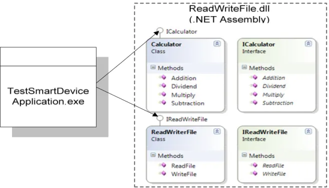
In this section, I have described the code generator tool that adds logging services to .NET component for Smart device by implementing proxy object concept. The tool takes .NET smart device component DLL file or portable EXE file as input and load this assembly. Tool read modules and Types information from DLL or EXE file that includes classes, methods etc. For each module of assembly, using System.Reflection library only populate class type in treeview control at parent root level and interface type and methods are populated at child root. ReadWriteFile.dll .NET Assembly Code Generator Tool
Visual Studio.NET
ReadWriteFileProxy.dll35
In .NET component interfaces have one or more methods, attribute etc. declaration and methods implementation exist in interface offering class. Based on user selected methods from one or more from same or different classes, tool will generate code for Csharp proxy class and dynamically create Microsoft Visual Studio.NET solution and within solution create CSharp SmartDeviceClassLibrary project and a complete set of configuration files. All proxy classes are dynamically included in new created project. The runtime generated complete set of files can be used with Microsoft Visual Studio .NET Compact framework to build a .NET smart device component implementing proxy object. The context diagram of tool is depicted in Figure 4.4.
In short a word, the tool generate is a complete set of files for a Visual Studio smart device solution, including both source code and configuration files by invoking Visual Studio's automation object model.
4.2.1.
Instruction to Generate Code
Figure 4.5 illustrate the graphical user interface of code generator tool, dropdown menu file contain submenu “Open .NET Assembly”. After click on “Open.NET Assembly” user can load desired smart device .NET assembly that is available in the form of DLL and portable EXE. After loading DLL or EXE file classes define in each module of assembly are listed in treeview control at top root level. Under each .NET define class; the interfaces implemented by the class are listed in treeview and under each interface; the methods defined by the interface are listed in treeview control. In current version of code generator tool, I have implemented only logging service through proxy object and it is not listed in treeview control because logging service is generated at runtime for each user selected methods. The filled tree contain a check box on left of each class, interface and method’s name that make it easy selection of classes, interfaces and operation or methods. By checked or unchecked root class node all its child node interfaces and methods will be checked or unchecked. After selection of one or more methods under same or different class, use can generate complete set of configuration files in which code for proxy class for each selected class and code for logging service for each method will be included. After clicking “Generate Code” button, input dialog is opened with purpose name for project and solution and location where new project will be created. If user wanted, he can change name of project
36
and solution and by clicking on “Browse” button can select desired the location for creation of new project. All three inputs; project name, location and solution name are mandatory for to generate code. After that on click “OK” button of input dialog, a Microsoft Visual Studio.NET SmartdeviceClassLibrary C# project will be created at location as defined above.
![Figure 2.1: .NET Component Interface [4]](https://thumb-eu.123doks.com/thumbv2/5dokorg/4436438.107378/18.918.291.631.338.520/figure-net-component-interface.webp)


![Figure 4.3: Mapping the solution/project hierarchy [10] .](https://thumb-eu.123doks.com/thumbv2/5dokorg/4436438.107378/32.918.112.815.122.555/figure-mapping-solution-project-hierarchy.webp)