Comparative analysis of
different pyrolysis techniques
by using kraft lignin
Master of Science in Engineering, Degree Programme in Chemical
Engineering
Jämförelse mellan olika pyrolys metoder
Husam Abbas
Faculty of health, science and technology Master in engineering: Chemical engineering Points: 30 ECTS
Supervisor: Assoc. Prof. Raza Naqvi R
Examiner: Prof. Magnus Lestelius 2019-05-28
Abstract
This thesis presents a comparison analysis between various pyrolysis techniques performed on kraft lignin. Numerous literature studies of pyrolysis techniques performed on kraft lignin are reviewed and analysed where different operation temperatures, catalysts and different heating methods are used to pyrolyze kraft lignin. Based on the collected data from the reviewed literature, calculations are performed to determine energy efficiency of each pyrolysis technique. The energy efficiencies are used to establish a comparison between various pyrolysis techniques. Energy efficiencies of all pyrolysis techniques are determined by using series of equations.
Dissimilarities of products composition are investigated between various pyrolysis techniques. Environmental impacts caused by lignin pyrolysis are reviewed and discussed. Uses of products produced from lignin pyrolysis are discussed to highlight the potential of using lignin as an energy resource to produce biooil, biochar and non-condensable gases (NCG).
Results show that energy efficiencies differ significantly between various pyrolysis techniques, where microwave-assisted pyrolysis (MAP) shows the highest energy efficiency. Products produced from pyrolysis show a wide range of uses in many industrial applications. Lignin based products have the potential to replace many petroleum-based products which may contribute significantly to decrease pollutants in nature and gas emissions caused by combusting fossil fuels.
Sammanfattning
Detta arbete presenterar en metod där en jämförelseanalys mellan olika pyrolysmetoder utfördes på kraftlignin. Många studier på pyrolys av kraftlignin granskades där olika pyrolystemperaturer, katalysatorer och olika uppvärmningsmetoder användes för att pyrolysera biomassan. Baserat på insamlade data utfördes beräkningar för att upprätta jämförelsemetoder mellan olika pyrolysmetoder. Exempel på en sådan jämförelse var energieffektiviteten för varenda teknik. Energieffektivitet bestämdes med användning av olika ekvationer där energivärden för pyrolysprodukter beräknades.
Skillnader i produktsammansättningen undersöktes mellan olika pyrolysmetoder. Miljöpåverkan orsakad av ligninpyrolys granskades och diskuterades. Dessutom diskuterades tillämpningar av pyrolysprodukter för att belysa potentialen att använda lignin som energikälla eller råmaterial.
Resultaten visade att energieffektiviteten skilde sig signifikant mellan olika pyrolystekniker, där mikrovågsassisterad pyrolys (MAP) visade den högsta energieffektiviteten. Produkter tillverkade av pyrolys visade ett brett användningsområde i många industriella tillämpningar. Pyrolysande lignin övervinner många utmaningar orsakade av att använda biomassa som råvaror. Användning av lignin har potentialen att ersätta många petroleumbaserade produkter som bidrar till att minska föroreningar i naturen och gasutsläpp orsakade av förbränning av fossila bränslen.
Dedication
To my parents, I want to express my sincere thanks and appreciation for their unlimited support. Without them I wouldn’t achieve what I am achieving today, and words are not enough to repay the sacrifices they made to raise me and my siblings. For my siblings, who have expressed unconditional love and support throughout my life. For my friends, who motivated me and supported me throughout my studies. For administrators in Karlstad university, may you keep your hard work on graduating well educated generations.
Acknowledgments
I would like to express my sincere gratitude for my supervisor Raza Naqvi, Associate Professor, for his constructive advice and feedback throughout this project.
I sincerely want to thank Robert Gustavsson and Lignocity for supporting me with data and information about kraft lignin obtained by Lignoboost process.
I also want to thank to my examiner Magnus Lestelius for his advices to overcome challenges faced during the project.
Table of Contents
1 Introduction ... 9
2 Aim and objectives ... 11
3 Background ... 12 3.1 Lignin ... 12 3.2 Kraft pulping ... 13 4 Pyrolysis ... 13 4.1 Conventional pyrolysis ... 13 4.1.1 Slow pyrolysis ... 14 4.1.2 Fast pyrolysis ... 14 4.1.3 Flash pyrolysis ... 14
4.2 Catalytic fast pyrolysis ... 16
4.3 Microwave assisted pyrolysis ... 17
4.4 Reactions temperature ... 18
4.5 Catalytic microwave assisted pyrolysis ... 19
5 Product streams ... 20 5.1 Bio-oil ... 20 5.2 Biochar ... 21 6 Process overview ... 21 6.1 Feedstock preparation ... 21 6.2 Pyrolysis ... 22
6.3 Hot vapor filtration ... 22
6.4 Condenser ... 22
7 Methodology ... 24
7.1 Materials ... 24
7.2 Assumptions ... 24
7.3 Modelling of the process ... 24
7.4 Lignin characteristics ... 25
7.5 Lower heating value and higher heating value ... 26
7.5.1 LHV values of the products ... 27
7.6 Energy efficiency ... 27
7.6.1 Energy obtained from products ... 27
7.6.2 Drying of the biomass ... 28
7.6.3 Pyrolyzing ... 29
7.6.4 Condensing ... 29
7.7 Data collection ... 30
7.7.1 Fast pyrolysis ... 30
7.7.2 Catalytic fast pyrolysis ... 31
7.7.3 Microwave-assisted pyrolysis ... 31
8 Result ... 33
8.1 Comparison of products mass yields ... 33
8.1.1 Char mass yields ... 33
8.1.2 Biooil mass yields ... 34
8.1.3 Non-condensable gases mass yields ... 35
8.2 Energy efficiencies of pyrolysis techniques ... 35
8.2.1 Fast pyrolysis (FP) ... 36
8.2.2 Catalytic fast pyrolysis (CFP) ... 36
8.2.3 Microwave assisted pyrolysis (MAP) ... 36
8.2.4 CMAP ex-situ ... 36
8.2.5 CMAP in-situ ... 36
8.3 Comparison between pyrolysis techniques ... 37
8.4 Products applications ... 41
8.4.1 Biooil uses ... 41
8.4.2 Biochar uses ... 42
8.4.3 Non-condensable gases ... 43
8.5 Environmental and economic impacts ... 44
9 Discussion ... 46
10 Conclusions ... 47
10.1 Recommendations for future work ... 48
11 References ... 50 Appendix A ... 56 Appendix B ... 58 Appendix C ... 60 Appendix D ... 62 Appendix E... 64
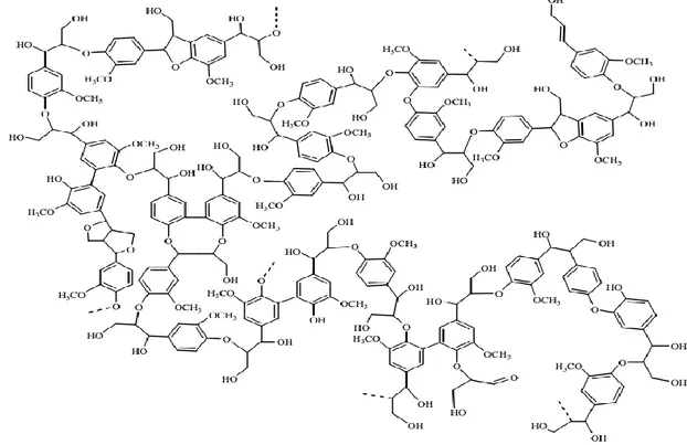
L
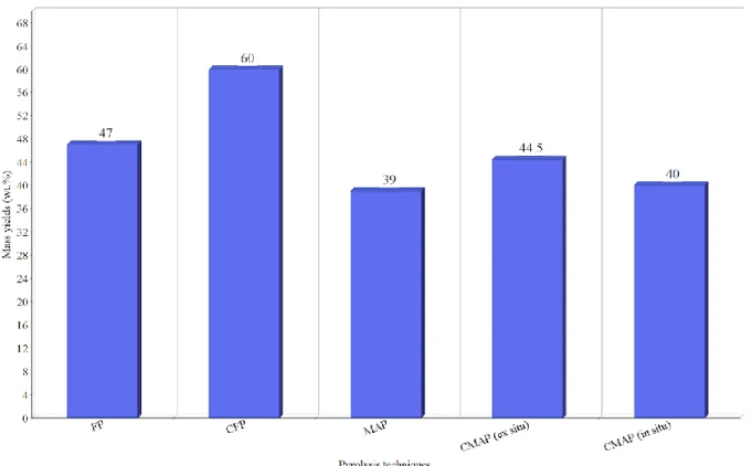
IST OF FIGURESFIGURE 1. LIGNIN STRUCTURE IN SOFTWOOD (18). 12 FIGURE 2.PYROLYSIS DIFFERENT STAGES. 25 FIGURE 3.BIOCHAR YIELDS FROM DIFFERENT PYROLYSIS TECHNIQUES (17,48,49). 33
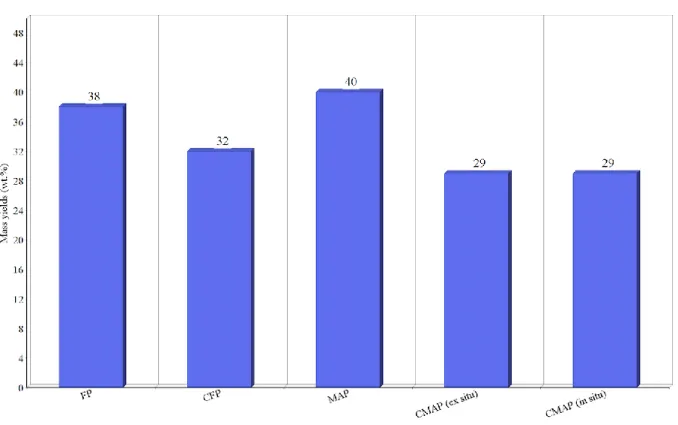
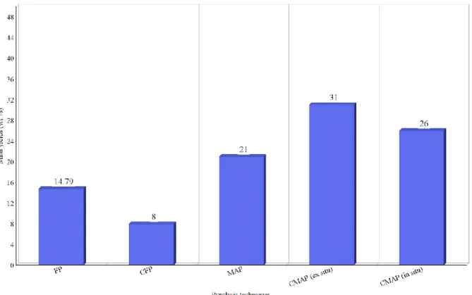
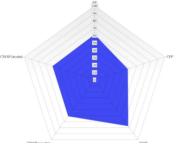
FIGURE 4.BIOOIL YIELDS FROM DIFFERENT PYROLYSIS TECHNIQUES (17,48,49). 34 FIGURE 5.NCG YIELDS FROM DIFFERENT PYROLYZING TECHNIQUES (17,48,49). 35 FIGURE 6.ENERGY EFFICIENCIES IN VARIOUS PYROLYSIS TECHNIQUES. 40
List of tables
TABLE 1.COMPARISON OF SLOW, FAST AND FLASH PYROLYSIS (25,26,27). ... 15
TABLE 2.CATEGORIES AND MEMBERS OF FUNCTIONAL CATALYSTS IN PYROLYSIS (15). ... 16
TABLE 3.A LIST OF DIFFERENT LINKAGES IN LIGNIN WITH THEIR BDE(32). ... 18
TABLE 4.ELEMENTAL COMPOSITION OF KRAFT LIGNIN. ... 25
1 Introduction
Petroleum is one of the main energy resources with well-derived fuels that have offered energy for industries and consumers for many decades. Requirements for using fossil fuels to gain energy in industries, transports, heating and many other technologies are increasing and amounts of available fossil fuels are decreasing (1). The word petroleum is derived from the Latin words petra which means rock and oleum which means oil. Petroleum consists of many hydrocarbon chains that exist at different phases depending on chains length. Lighter hydrocarbon chains of butane, propane, ethane and methane exist at gas phase meanwhile heavier chains are at liquid and solid phases (2).
Extraction and refining industries of petroleum emit large amounts of hazardous gases, produce non-degradable by-products, and need large amounts of energy and water. Emitted gases introduced into the atmosphere lead to climate changes, non-degradable products and waste water are accumulated in nature causing pollution and harm to animals. As constant using of petroleum-derived products lead to increased harmful impacts on environment and decreased amounts of fossil fuels resources, the need for alternate resources that could contribute to reduction in greenhouse gases and maintaining a sustainable development is necessary (3).
The harmful impacts on both environment and public health are raising politic, economic and academic concerns worldwide. Consequently, switching from conventional energy resources to renewable energy resources is an obligation to achieve a sustainable future development. Therefore, in recent years many researchers have focused on producing new generations of biofuels and biomaterials by utilizing renewable and non-polluting resources. Lignocellulosic biomass is an example of such alternatives that have shown promising solutions to the problems caused by fossil fuels. Biomass has the ability to substitute many petroleum-based fuels in many technologies as it is a platform for a wide variety of chemicals (4,5).
Lignocellulosic biomass consists of three main organic compounds: cellulose (34-45 wt.%), hemicellulose (19-34 wt.%) and lignin (11-30 wt.%). Cellulose and hemicellulose are utilized mostly in paper and pulp industries, meanwhile lignin is usually burned to generate heat. The three main compounds consist of hydrogen, carbon and oxygen, and differ from each other in chemical structure and elemental composition. Therefore, biomass is a qualified raw-material for conversion into hydrocarbons identical to those in petroleum-based products (6). Recently, lignin has emerged as an important energy resource owing to its quantity and availability. The biological function of lignin in wood is to glue cells to prevent them from separating and also to protect the wood from microbial attacks. In the conventional paper and
pulp industries lignin is often extracted from wood tissues and considered as law-value by-product, therefore it is burned to supply the mills with heat (7). However, lignin has the potential in various sectors, such as polymers, cement, fibres and activated carbons. Since kraft pulping process is the main industry responsible for paper and pulp production, enormous amounts of lignin are available in the black liquor obtained from the cooking stage in these industries. About 97% of the lignin is burned to generate heat in mills and has not been effectively utilized to produce valuable products (8).
To date, many studies reported biomass conversion into valuable products by using different conversion processes such as: gasification, anaerobic digestion (fermentation) and pyrolysis. Conversion of biomass leads to production of biofuels and valuable platform bio-based chemicals. Fermentation of biomass includes using enzymes to digest the material into biogas. Gasification is a thermochemical conversion process of biomass at elevated temperatures into non-condensable gases (NCG). Pyrolysis is the thermal decomposition of biomass at elevated temperatures in an anaerobic environment into lower molecular weight compounds, products produced are biochar, condensable gases that are condensed into liquids to form bio-oil, and non-condensable gases consisted of methane, hydrogen and other low molecular weight gases. Depolymerization of celluloses, hemicellulose and lignin during pyrolysis occur at different temperatures where lignin requires higher temperature than those for cellulose and hemicellulose. Compared to other conversion processes, thermochemical conversion such as pyrolysis is more energy efficient and cost-effective than biological methods (7,9,10).
So far, numerous studies reviewed pyrolysis and catalytic pyrolysis results of lignin depolymerization by using different heating methods and catalysts. Heating methods operating at different parameters result in alternated product composition. Typical pyrolysis temperature of lignin range from 200 C to 500 C, yielding biochar, bio-oil and non-condensable gases (7). Farrokh et al. (11) studied slow pyrolysis of lignin from wood-based ethanol production where biochar had the major yield. Fan et al. (12) carried out fast pyrolysis of lignin and investigated parameters effects on the product yield and on bio-oil quality. Patwardhan et al. (13) investigated fast pyrolysis of lignin by using micro-pyrolyzed coupled with GC-MS/FID (flame ionization detector) to analyse bio-oil quality. Choi et al. (14) carried out catalytic fast pyrolysis (CFP) of lignin by using TI-mini pyrolyzer and implemented various catalysts to investigate the effects on the final products with and without catalysts. Besides conventional heating methods, other novel heating methods, such as microwaves, are attracting attention worldwide
to heat distribution, products quality and chemical reactions rate (15). Fan et al. (16) reported the effects of microwave-assisted pyrolysis on lignin by using different microwave susceptors to investigate product yield and composition. In another comparative study of microwaves as a heating resource, catalysts are implemented to enhance products quality and to accelerate chemical reaction rate (17).
2 Aim and objectives
The objective of this study is to establish a comparative analysis between different pyrolysis techniques by using kraft lignin as raw-material. This thesis collects data obtained from different pyrolysis techniques, calculations are performed to determine the energy efficiency of each method.
Some key research questions studied in this thesis are summarized as:
• What is the potential of biochar and biooil production from lignin pyrolysis using different pyrolysis techniques?
• How much the qualities of pyrolysis products (biochar and biooil) are different when produced from various techniques?
• Which of the pyrolysis method shows highest energy efficiency?
• What are the most promising commercial applications of biochar and biooil from lignin?
3 Background
3.1 Lignin
Lignin is an amorphous, heterogenous and aromatic biopolymer. The structure is very complex with high importance in tress. Besides its main functionality as a bonding agent it provides wood protection against microbial attack and increases wood strength. The structure is very complex due to presence of substituted functional groups and side chains, highly branched and crosslinked three-dimensional web polymerized from three different monomers called monolignols (p-coumaryl, coniferyl and sinapyl alcohol) with varying number of methoxy groups in each monolignol, see figure 1. Lignification (synthesis of lignin) of the monomers lack presence of enzymatic control leading to unsystematic links between monomers, thus it results in a very complex structure. The monolignols form different types of ether bonds (0-α, β-5, β-1, β-o-4, α-o-4, 5-5) and carbon-carbon linkages. After polymerization, monolignols are converted into p-hydroxyphenyl (H), guaiacyl (G) and syringyl (S) units respectively. The monolignols composition differs widely from a plant to another, also from a cell to another. Unfortunately, Lignin structure is not yet completely understood because of its complexity and heterogeneity, therefore, different structures of lignin are suggested in different studies. (18,19)
3.2 Kraft pulping
Pulping is the process of converting wood into wood pulp. Chemical pulping is one of the most common pulping processes in industries, where wood chips are treated with chemicals at elevated temperatures to break down lignin which binds cellulose fibres together in a stage called delignification. Kraft pulping (also known sulphate pulping) is a chemical process and is the dominating method today. In kraft pulping wood chips are digested by cooking them in a white liquor at high temperature and pressure. The white liquor is consisted of sodium hydroxide (NaOH) and sodium sulphide (Na2S). After cooking, white liquor is converted into
black liquor containing dissolved lignin together with additional organic and inorganic compounds. Lignin is the main by- product in pulp and paper manufacturing industries, it is available as a dissolved component in the black liquor, which is usually burned in a recovery boiler to generate power in mills (20,21).
4 Pyrolysis
4.1 Conventional pyrolysis
Pyrolysis is a known thermochemical process defined as a thermal decomposition of biomass at elevated temperature under the absence of oxygen. There are three types of conventional pyrolysis that differ from each other in residence time, temperature range and production consistency (14):
• Slow pyrolysis • Fast pyrolysis
• Ultra-fast/flash pyrolysis
All three types aim to decompose biomass feedstocks into biooil and biochar but differ from each other in products consistency. Pyrolysis generally results in a change of the chemical composition in the treated material. The word is derived from the two Greek words: ‘pyro’ which means fire and ‘lysis’ means separating. Pyrolysis of lignocellulosic material produces volatile compounds, gases and solid residues consisted of hydrocarbons. Temperature required to decompose organic compounds depends on type of the compound. The three types of conventional pyrolysis operate at different temperatures which lead to dissimilar yield composition in the products. Fast pyrolysis contributes to larger bio-oil generation by having high temperature and short hot vapor residence time. Ultra-fast/flash pyrolysis maximizes gaseous products by operating at very high temperatures, high heating rate and long hot vapor
residence time. Meanwhile, slow pyrolysis increases production of solid biochar by operating at low temperature and low heating rates (7,22).
Typical combination of reactions occurring in pyrolysis are dehydration, depolymerization, re-polymerization, fragmentation, rearrangement, and condensation. Yet, reactions occurring in pyrolysis are not fully understood due to complex biomass composition and high operations temperatures (23).
4.1.1 Slow pyrolysis
Slow pyrolysis, also termed as conventional pyrolysis in some literatures, is the oldest pyrolyzing technique among other pyrolyzing techniques with large focus on producing biochar. It is characterized by low temperature, slow heating rate and long residence time for vapor products to generate larger proportion of biochar. Raw-material size ranges from 2-4 mm during pyrolysis. The production streams from this operation are usually not condensed, but instead used to provide heat for the pyrolysis (24). In slow pyrolysis temperature reaches 500 C with heating rates of 0.1-2 C/sec and residence time ranging from several minutes to several hours. The main drawback of slow pyrolysis is producing high yield of non-condensable gases and low yields of bio-oil (25).
4.1.2 Fast pyrolysis
In contrast to slow pyrolysis, fast pyrolysis technique is more advanced technique with higher pyrolysis temperatures. Residence time for vapours are much shorter than it is for slow pyrolysis. The aim of this technique is to produce higher yields of bio-oil and reduce non-condensable gases due to controllable process parameters. Fast pyrolysis applies a temperature higher than 500 C to maximize bio-oil production, 10-200 C/sec and short residence times. Since biomass has low thermal conductivity, the material is grounded to a particle size less than 3 mm to provide good heat transfer. Residence time is less than 2 sec for the hot vapours, therefore most secondary reactions are avoided. The central issue of pyrolyzing biomass is to provide a uniform heat distribution and heat transfer to the feedstocks. (24,26). Products composition depends on temperature, biomass type, residence time and biomass ash content. It is reported that bio-oil yield as high as 75 wt.%, 12 wt.% biochar and 13% non-condensable gases are obtained from biomass pyrolysis (26).
4.1.3 Flash pyrolysis
Flash pyrolysis (even called ultra-fast pyrolysis) is developed to increase high-grade bio-oil production. The technique requires very high temperatures with very high heating rates and short residence time. Temperatures range of flash pyrolysis is located in an interval of
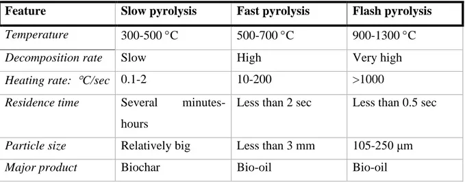
900-1300 C, heating rate is rapid with more than 1000 C/sec, and residence time is less than 0.5 sec. The feedstock is grounded to a very small particle that does not exceed 250 μm (27). Table 1 below simply compares all three pyrolysis techniques mentioned above:
Table 1. Comparison of slow, fast and flash pyrolysis (25,26,27) .
Feature Slow pyrolysis Fast pyrolysis Flash pyrolysis Temperature 300-500 C 500-700 C 900-1300 C Decomposition rate Slow High Very high Heating rate: C/sec 0.1-2 10-200 >1000 Residence time Several
minutes-hours
Less than 2 sec Less than 0.5 sec
Particle size Relatively big Less than 3 mm 105-250 μm Major product Biochar Bio-oil Bio-oil
Biooil produced from pyrolysis of biomass can be burnt directly in various applications. However, when compared to fossil fuels, bio-oil suffers from several drawbacks such as complex chemical composition, immiscibility with fossil fuels and miscibility with water (leading to changes in viscosity), high oxygen content, low hydrogen to carbon ratio, high pH (cause corrosion to reactors), high density, lower heating values (harder to combust) and low viscosity. Therefore, efforts are needed to improve bio-oil quality to make it more identical to petroleum-derived fuels (23).
To date, several efforts are made to enhance bio-oil characteristics by increasing its density, increasing hydrogen to carbon ratio and minimizing oxygen content. These enhancements are achieved by upgrading the bio-oil product or by introducing catalysts to the biomass feedstocks before pyrolyzing. An example of such developed techniques is catalytic deoxygenation which includes catalytic cracking and hydrodeoxygenation (HDO), where solid acid catalysts and metal catalysts are used in catalytic cracking and HDO, respectively. Unfortunately, these developed methods have drawbacks due to high operation costs, low quality products and short catalyst life time (15).
Another alternative technique termed as catalytic fast pyrolysis (CFP) is attracting attention recently due to causing enhancements in bio-oil quality. Catalysts are introduced to the biomass to carry on deoxygenation, cracking, isomerization, aromatization, condensation and oligomerization reactions in order to improve bio-oil quality. Numerous reviews reported effects of different catalysts by using them in two different ways referred to as in situ and ex
situ. The in situ involves mixing large portions of the catalysts directly with the biomass to ensure sufficient contact with the biomass in the same reactor. Meanwhile, in ex situ catalysts are placed in a secondary reactor that only upgrades the pyrolytic vapor (15,17). Different catalysts are used in different experiments to investigate the effects on bio-oil quality, some of these catalysts are divided into three categories and summarized in table 2 below (15):
Table 2. Categories and members of functional catalysts in pyrolysis (15).
Soluble inorganics Metal oxides Zeolites based catalysts • NaCl • NaOH • Na2CO3 • KOH • K2CO3 • K3PO4, • ZnCl2 • MgCl2 • CaO • MgO • NiO • CuO • Al2O3 • TiO2 • Fe3O4 • ZSM • HZSM-5
Also, other heating resources such as gas heater and oil bath are applied in heating biomass to increase volume fraction of the bio-oil. The operation starts by generating heat in the system and then transferring it to the biomass by convection, conduction and irradiation, but these heating methods suffer from low efficiency (28).
4.2 Catalytic fast pyrolysis
Since lignin has low hydrogen to carbon ratio, hydrogen donors are one way to enhance bio-oil quality. Catalysts mentioned in table 2 aim to decrease oxygen content and increase hydrogen to carbon ratio by carrying deoxygenation of the bio-oil via dehydration, decarbonylation, decarboxylation and aromatization reactions (29).
During catalytic pyrolysis, oxygenated compounds are eliminated in form of H2O and CO2,
therefore molecular weight is reduced, and chemical structure is alternated in a way that resembles petroleum-derived products. Among all available catalysts, the amino silicate zeolites have dominated as catalysts in catalytic pyrolysis. Zeolites activity is determined by two key properties, pour size and density of active acid sites (23). It is reported that conventional microporous sized zeolites are more selective toward mono-aromatics, while mesoporous sized are more selective toward alkyl-phenols (29). The acid sites are depended on Si/Al ratio; thus, acidity is controlled by alternating the Si/Al ratio. Yet, CFP and conventional pyrolysis are not
methods with high potential due to low yield, heat loses to the surroundings and damage to reactors (29)
4.3 Microwave assisted pyrolysis
Microwaves are a form of electromagnetic radiation where energy is transmitted, reflected or absorbed. Microwaves have frequencies varying from 0.3 to 300 GHz and wavelengths ranging from 0.01 to 1 m, some of these frequencies interfere with frequencies used for other applications such as telecommunications, navigation and radar. Therefore, a certain of microwave frequencies are reserved by Federal Communications Commissions (FCC) for industrial, medical and scientific fields. Microwaves used for chemical purposes have frequencies of 0.915 GHz and 2.45 GHz (22).
Microwave irradiation is widely used as a heating method in many different industrial applications because of its to many advantages. In contrast to conventional heating methods, microwave assisted pyrolysis transport heat to the material without physical contact between the heat source and material. The use of microwaves as a heating method has gained interest over the last decade since it offers a rapid process, selective heating, high volumetric heating and uniform power distribution. Heat distribution differs between conventional heating and microwave heating. Temperature distribution in the biomass heated by a conventional method is much higher at the outer surface than it is in the interior layers. In contrast, biomass heated by microwaves has uniform heat distribution (22).
Exposing a material to an electromagnetic radiation in the microwave range causes charged particles to rotate, thus electromagnetic energy gets converted into heat in a process called dielectric heating. Energy penetration into the material depend on applied frequencies (15,31).
Materials ability to transform electromagnetic energy into thermal energy differs between various materials. Transforming ability of a material is defined as dielectric loss constant (tan δ) in the equation (1)
tan δ = ε´´ ε´⁄
(1)
where dielectric loss (ε´´) (imaginary permittivity) is used for measurement of electromagnetic conversion into heat and dielectric constant (ε´) (real permittivity) characterizes the capacity of a material to store electromagnetic energy. Thus, loss tangent demonstrates how well a material convert electromagnetic energy into thermal energy. Materials are categorized into low
microwave absorbing materials with tan δ < 0.1, medium absorbing materials with 0.5 < tan δ < 0.1 and high absorbing materials with tan δ < 0.5 (15,31).
Penetration depth into materials varies greatly between different materials because of their different absorbing properties. Several factors such as chemical composition, physical structure and waves frequency determine how much a wave can penetrate into a material. Some materials have good absorbing ability which makes it a challenge for some heating processes, due to an uncontrolled heating. In contrast, other material with poor absorbing ability such as biomass require to addition of materials with high tan δ called microwave absorbers in order to achieve desired temperature by a rapid heating process when using microwaves heating. Solid carbon based materials (SCBM) and metal oxide microwave absorbers (MOMA) are examples of materials with high tan δ that can be blended with biomass to facilitate a rapid heating process for biomass (15).
4.4 Reactions temperature
Reactions that occur in the pyrolysis are decompositions of large hydrocarbon molecules into smaller molecules. In contrast to cellulose and hemicellulose, lignin is more difficult to decompose, it starts to decompose in a wide temperature range, about 200-500 C (7). Depolymerization of lignin during pyrolysis is more challenging than it is in cellulose and hemicellulose due to the presence of carbon-carbon bonds (5-5´ links) that makes the depolymerization of lignin more energy-consuming. Explanations of lignin depolymerization reactions during pyrolysis are not fully understood in today´s literature, some reactions are more recognized in several studies, such as radical forming due to dissociation of carbon-carbon and carbon-oxygen bonds, radicals formed are key reaction for lignin depolymerization (32).
For depolymerization of molecules, specific amount of energy is needed to cleave bonds between units. Bonds dissociation energy (BDE) is used in literature to indicate the required energy to break a bond. In account of linkages variety of a lignin structure, pyrolysis reactions occur in multiple stages named primary and secondary stage. In the primary stage (200-400 C), linkages with BDE of 40-60 kcal/mol are more likely to be cleaved. In contrast, homolytic cleavages of bonds with BDE higher than 60 kcal/mol will occur at the secondary stage (>400 C of the reactions. Below are some linkages found in a lignin structure with their BDE summarized in table 1 (32).
Table 3. A list of different linkages in lignin with their BDE (32).
As it is demonstrated in table 3, most bonds require energy higher than 60 kcal/mol to be cleaved, therefore homolysis of C-C and C-O bonds occur during secondary lignin pyrolysis stage. Only two bonds are likely to cleave during primary pyrolysis, α-O-4 and O-CH3.
However, experiments show that O-CH3 bonds are usually cleaved at evaluated temperatures
in the secondary pyrolysis stage (32).
Performing thermogravimetric reaction and derivative thermogravimetric analysis of lignin demonstrates that most reactions of the polymer during primary pyrolysis occur at temperature range of 200-400 °C with highest weight rate loses at temperatures around 350 °C. During secondary stage of pyrolysis, when temperature interval is about 400-450 °C other compounds such as aromatic methoxy groups become highly reactive and more likely to be transformed into phenols (32).
Aliphatic groups and other side chains start to break out from lignin structure at around 300 °C. Phenolic compounds together with small molecules such as ketones, aldehydes, and acids are released at temperatures around 500 °C. Increasing of pyrolysis temperatures leads to higher production of biooil (usually 500-650 °C), but exceeding this limit will cause demethoxylation, demethylation, and deoxygenation of primary pyrolysis products which will lead to increasing of gas stream instead of biooil (12).
4.5 Catalytic microwave assisted pyrolysis
Microwaves offer uniform heat distribution during pyrolysis. However, biomass is a poor microwave absorbing material, thus, implementing catalysts in microwave-assisted heating contributes to a rapid heat distribution (33). Enhancing biooil quality to be compatible with petroleum-derived fuels is investigated by several methods. In addition to the methods mentioned above for biooil improvement, another method is investigated in several studies called catalytic microwave assisted pyrolysis (CMAP). It is a method at an early development stage where catalysts are implemented to enhance product yield and selectivity. CMAP is
O-CH3 56 α-O-4 55 β-O-4 68-71 4-O-5 83 Dibenzodioxin 68-114 5-5 113-117 Phenylcoumaran 61 Resinol 68-83
divided into two categories: 1) catalysts are mixed with biomass before entering the reaction chamber (in-situ CMAP) and 2) ex-situ doesn’t involve mixing of catalyst with the biomass in contrast to the in-situ method. Microwaves absorbers are preheated to a certain temperature, followed by convection heating of the catalysts and ending up with feeding biomass into the microwave oven (ex situ CMAP). A noteworthy difference is the controllable and uncontrollable catalytic temperature in in situ and ex situ, respectively. Thus, ex situ MCAP of biomass offers higher bio-oil yield and better selectivity (34).
5 Product streams
When biomass is subjected to pyrolysis it results in depolymerizations and fragmentation reactions. As mentioned earlier, pyrolysis of biomass results in production of bio-oil, biochar and non-condensable gas. Different factors and operation parameters such as biomass type, pyrolysis temperature and residence time govern volume fraction of each product.
5.1 Bio-oil
Bio-oils are composed of small size molecules derived from three main components cellulose, hemicellulose and lignin. Bio-oil is a dark brown liquid with high viscosity composed of multicomponent mixtures containing high amounts of oxygen (26-60 wt.%), water (10-30 wt.%) and relatively little sulphur and nitrogen trace. Besides its production from renewable sources, combustion of bio-oil contributes to reduction of CO2 in the atmosphere.
Unfortunately, replacing petroleum-derived oils with biooils is quite a challenge because of poor biooil quality, high oxygen content, high acidity, susceptible to aging, easy degraded by microbial attacks and high-water content. These properties make the bio-oil hard to storage and transport, decreases the heating value and less compatible to crude oil. Another point of view is that bio-oil can be used for applications other than fuels, for example it is used as an agent for skin treatment (35,36)
To modify bio-oil quality many parameters and factors are controlled to alter chemical and physical properties of the products. Examples of such parameters are biomass types and composition (varies greatly from a tree to another), reactors configuration, heating method including temperature and residence time, catalyst type and properties. Several studies show that improvements of bio-oil are achieved by using CFP, MAP and CMAP with adequate catalysts. Results show that using these methods enhanced bio-oil quality by reducing oxygen and acid contents, and increasing fraction of low molecular weights hydrocarbons, aromatics, aliphatic and phenolics (36)
Except being a combustion fuel in turbines, diesel engines, boilers, transport fuels and Stirling engines, bio-oil is a platform for production of many chemicals used in different applications. The presence of phenolic, carboxylic and carbonyl groups promote production of different chemicals. For instance, adding lime to bio-oil creates a reaction with carboxylic acids and phenols to form calcium salts and phenates. The obtained product called BioLime is a liquid suspension composed of 50 wt.% and 7-14 wt.% water and calcium, respectively. Injecting BioLime into flue gas streams facilitate capturing 90-98 % of SOx emissions from flue gases
(37).
Another potential application of bio-oil is their usage as an efficient biodegradable nitrogen fertilizer. Nitrogen fertilizer are created by adding NH2- containing materials to biooil, followed
by a reaction with carbonyl carbons to form various imide and amid bonds. This type of fertilizers contributes to environmentally friendly outcomes, it reduces pollution in ground water and improves soil´s physical qualities. Additionally, bio-oil shows promising potential to act as insecticides and fungicides or as a preservative agent to replace creosote (37).
5.2 Biochar
Studies show that utilization of biochar in soil leads to many advantages, especially in seasonally frozen soil areas. Example of these advantages is that biochar improves stability of the soil structure, retrains nutrients, reduce greenhouse emissions, increases water storage capacity and improves water retention. Another significant advantage that leads to enhancement of soil is the resist that biochar offers against press applied to a soil that causes shrinkages and leads to compaction (38).
6 Process overview
As feedstocks, kraft lignin is extracted from black liquor that is delivered from Nordic Paper in Bäckhammar where softwoods are used as raw materials for paper and pulping. Kraft lignin is separated from the black liquor in a process called Lignoboost (39). At this stage lignin is filtered to obtain a dry matter of 35-40 %. Secondly, lignin is washed and dried to a dry matter of 65 %. Finally, lignin is transported to Germany for further drying process, where lignin gains a dry substance of 95%.
6.1 Feedstock preparation
To begin the process, it is worthy to start with a stage for handling and preparation of the feedstocks. The aim of this stage is to minimize moisture content, eliminate troublesome elements and process the material to acceptable sized material in the form of pellets (6 x 40 mm). Moisture content is decreased to increase heating value of the biomass and to increase
biooil quality. For kraft lignin obtained from Lignoboost in Lignocity, moisture content is approximately 30%. After drying moisture content is decreased to 1-2%.
6.2 Pyrolysis
Pyrolysis is carried out by several techniques. The alternation of temperature and residence time result in varied product quality and composition. A traditional way is to heat up the pyrolyzer to the operation temperature followed by feeding the biomass feedstocks into the pyrolysis reactor. Thus, biomass is depolymerized into gases and solid residues (26).
6.3 Hot vapor filtration
Pyrolysis vapours produced are existed from the reactor at elevated temperatures towards a vapor filtration. Prior condensation into liquids vapours are necessarily filtered from fines such as solid particles and bio-chars to enhance biooil quality. Studies demonstrated that hot vapor filtration is necessary to prohibit production of polyaromatic hydrocarbons as it is caused by char fines (41,42).
Several studies investigated hot vapor filtration effects on biooil characteristics. Chen et al. (41) demonstrated that hot vapor filtration decreased biooil yield 2% by weight. Water content and pH showed higher values compared to non-filtered products, meanwhile alkali metals content showed lower values. In another study by Peterson et al. (42) hot vapor filtration followed by fractional condensation were investigated by filtering the pyrolysis vapours over a titania-supported molybdenum heteropolyacid in a process named catalytic hot-gas filtration (CHGF). Results from this experiment showed removal of foulants, reduction in oxygen content and introduction of alkyl radicals under hydrogen-rich environment.
6.4 Condenser
After pyrolysis and hot vapor filtration, gases are condensed in a condenser and biooil is obtained. Several studies have investigated different methods of gas condensation. Typical pyrolysis condensers consist of an individual reactor where a single liquid product is obtained, other systems includes multi-stage condensers where gases are fractionated into multiple liquid products. The purpose of multi-stage condensation process is to improve biooil quality. Condensation is important to consider because of its ability to modify biooil properties. Using a series of condensers condense gases at different temperatures. Thus, it contributes to higher biooil quality production and less energy consumption (43)
Papari et al. (44) investigated condensation effects on biooil by developing a two stage condensation process. Temperature in first condenser was altered between 50 °C and 90 °C, while the second condenser temperate was kept constant at 4 °C. Results of this approach
showed a decreased acidity in product obtained from first condenser, besides removal of light ends such as methanol and acetol. Other characteristics such as water content and heating value were decreased and increased, respectively.
7 Methodology
The comparative analysis is based on determining energy efficiency of each method. Impacts on environment, products streams composition and their applications are analysed and discussed. To our knowledge, comparison analysis has not been applied on lignin pyrolysis. Therefore, this project collects experimental data from literature to perform calculations that are used for the comparison.
7.1 Materials
The black liquor is delivered from Nordic Paper in Sweden, where softwoods are used as raw materials for paper and pulp production. Kraft lignin is separated from the black liquor by the Lignoboost process. At this stage lignin is filtered to obtain a dry matter of 35-40 %. Secondly, lignin is washed and dried to a dry matter of 70 %.
7.2 Assumptions
Some assumptions are considered to avoid complexity during calculations: • No heat losses to the surroundings are considered.
• The system is a steady state system.
• Lignin dissimilarity in elemental composition is ignored if the difference is too small. • 1 kg of the feedstock with 30% moisture is used as the basis for the calculations.
7.3 Modelling of the process
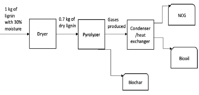
With the purpose of defining a mass balance, a process model is designed to demonstrate the entire process of lignin pyrolysis (figure 2). The process starts with a drying stage to evaporate the water, where moisture content of the lignin input is 30%. Dry content is assumed to be 100% after the drying stage. Thereafter, lignin is pyrolyzed to produce gases and biochar. Gases exist the reactor and enter a condensing step where bio-oil is obtained. Biochar is collected when reactions are completed, and bio-oil is upgraded to be used in further applications. The calculations performed in this project are calculated by hand.
Figure 2. Pyrolysis different stages.
The pyrolysis process starts with a drying step which is a common stage in pyrolysis techniques with the purpose to remove moisture content from the feedstock. The lignin enters the dryer with 30% moisture content and heat is supplied to increase its dry content, it is assumed that all moisture in the lignin is removed when drying is completed. The dried lignin enters the pyrolyzer where heat is supplied to depolymerize the material into low molecular-weight compounds. Heat is supplied either by conventional heating sources or by microwaves, the operation temperature differs between various techniques with an interval of 450-900 C. Gaseous products leaving the pyrolyzer enter a filtration step to remove biochar and ash particles. Following the filtration, gaseous products are condensed into liquids to obtain biooil while non-condensable are collected to obtain syngas. When pyrolysis is completed, solids residues remained in the pyrolyzer are collected as biochar.
The obtained biooil has some properties -such as oxygenated compounds and high water content- that make it poor as a fuel. Therefore, some upgrading techniques can be used to improve biooil quality and make it more compatible with fossil fuels.
7.4 Lignin characteristics
The proximate analysis for kraft lignin is collected from Lignocity. The following table 4. represents elemental composition of the kraft lignin. The following elemental composition is received from Lignocity.
Table 4. Elemental composition of kraft lignin.
C 63-66 H 5.7-6.2 O 26-27.5 S 1.5-3 N 0.1-0.2 Cl 0.01 A 0.01-1 Moisture content 30-35%
7.5 Lower heating value and higher heating value
The heating value describes the amount of heat released during combustion of a specific compound. Heating values of hydrogen-carbon compounds are expressed in terms of higher heating values (HLV) and lower heating values (LHV). When hydrocarbons fuels are burned water is released in form of steam, the released water steam stores energy in it as it is vaporised at elevated temperatures. HHV (also known as gross calorific value) and LHV (also known as net calorific value) differ from each other in considering the latent heat stored in the vaporised water. HHV is determined by summing the heating values of all the produced products, including H2O. In contrast, LHV sums the energy of the produced products except for the
energy stored in water (45).
Most of the literature studied in this work considered HHV instead of LHV to characterize products quality. Although, LHV of each product varies depending on the biomass type, pyrolysis methods and upgrading techniques. As a result, LHV values are chosen depending on the similarity of the biooil/biochar/NCG composition with other biomaterial products where LHV values are available. In this work, LHV is used instead of HHV during calculations. LHV is obtained by collecting data from literature when available, or by using formulas where LHV is calculated (46):
𝐿𝑉𝐻𝑙𝑖𝑔𝑛𝑖𝑛= 𝐻𝐻𝑉𝑙𝑖𝑔𝑛𝑖𝑛− 10.55 × (𝑊 + 9𝐻)
(2) Where:
LHVlignin = lower heating values for lignin.
HHVlignin = higher heating values of lignin.
W = moisture content.
7.5.1 LHV values of the products
One of the challenges during the study of this project is to find LHV values for the produced products from each technique since products differ somehow in chemical composition. Therefore, it is assumed that bio-oil had the same LHV of 17.2 MJ/kg after condensation in all techniques. Biochar is determined by the following equation:
𝐿𝐻𝑉𝑐 =
∑ 𝐿𝐻𝑉 𝑛
(3)
Equation 3 demonstrates that the lower heating value of biochar is determined by taking the average value of various biochar obtained from pyrolyzing different biomass types. LHVc
stands for lower heating values of biochar, LHV is the value of each biochar and n is the number of used values. Biochar values used in equation (4) are obtained from coniferous trees bark, coniferous trees bark biochar, sawdust, sawdust biochar, wheat straw, wheat straw and Miscanthus straw (47).
7.6 Energy efficiency
To establish a comparison between different pyrolysis techniques, data for products yield is collected from literature to determine energy efficiency of each technique. In order to calculate energy efficiency, equation (5) is used:
𝜂 = 𝑄𝑝𝑟𝑜𝑑𝑢𝑐𝑡𝑠+ 𝑄𝑟𝑒𝑐𝑜𝑣𝑒𝑟𝑒𝑑 𝑄𝑑𝑟𝑦𝑖𝑛𝑔+ 𝑄𝑝𝑦𝑟𝑜𝑙𝑦𝑠𝑖𝑠+ 𝑄𝑆𝐹
× 100 (6)
Where:
𝑄𝑑𝑟𝑦𝑖𝑛𝑔= energy required to vaporise water from the feedstock.
Qpyrolysis = energy required to increase feedstocks temperature in the pyrolysis reactor.
QSF = energy offered by lignin as a solid fuel.
Qproducts = energy recovered in the final products.
Qrecovered = energy recovered from condensing hot steams and vapors.
QSF is determined to be as the high heating value of lignin as a solid fuel with a value of 27
MJ/kg
7.6.1 Energy obtained from products
Qproducts is determined by summing the energy content in the products obtained from the
pyrolysis as shown in the equation (7)
𝑄𝑝𝑟𝑜𝑑𝑢𝑐𝑡𝑠 = 𝑄𝐶+ 𝑄𝐵𝑂+ 𝑄𝑁𝐶𝐺
(8)
Where QC, QBO and QNCG are the energy values of biochar, biooil and non-condensable gases,
respectively. Each term in equation 3 is determined by equations (6-8) 𝑄𝑐 = 𝑚𝑙× 𝐿𝐻𝑉𝐶× 𝑌𝑐 (6) 𝑄𝐵𝑂 = 𝑚𝑙× 𝐿𝐻𝑉𝐵𝑂× 𝑌𝐵𝑂 (7) 𝑄𝑁𝐶𝐺 = 𝑚𝑙× 𝐿𝐻𝑉𝑁𝐶𝐺× 𝑌𝑁𝐶𝐺 (8) Where:
YC = mass yield of biochar in weight %.
YBO = mass yield of biooil in weight %.
YNCG = mass yield of non-condensable gases in weight %.
ml = mass in kilograms of the lignin input.
LHVC = lower heating values of biochar.
LHVBO = lower heating values of bio-oil.
LHVNCG = lower heating values of non-condensable gases.
LHVNCG consists of various gases, each gas has a specific heat value and amount. Thus, heat
offered from each compound is calculated separately and are added together to determine the total non-condensable gases value.
7.6.2 Drying of the biomass
Before entering the pyrolyzing reactor, lignin needs to be dried to reduce moisture content. When drying biomass, heat will be supplied to increase the feedstocks temperature and to vaporise water. Therefore, Qdrying is calculated by equation (9):
𝑄𝑑𝑟𝑦𝑖𝑛𝑔 = 𝑄𝑙𝑖𝑔𝑛𝑖𝑛+ 𝑄𝑊𝐻
(9) Where Qlignin is the supplied energy to increase lignin temperature and QWH is the required
energy to increase moisture temperature from ambient temperature to vaporising temperature. Energy required to vaporise water from the lignin is determined by equation (10):
𝑄𝑊𝐻 = 𝑄1+ 𝑄2
(10)
Where Q1 and Q2 are the sensible heat and the latent heat, respectively. The sensible heat and
𝑄1 = 𝑚𝑤 × 𝑐𝑝,𝑤× (𝑇2− 𝑇1) (11) 𝑄2 = 𝑚𝑤𝐿 (12) Where 𝑚𝑤 is the moisture mass in kilograms, 𝑐𝑝,𝑤 is the specific heat ratio of water, T2 is the
desired temperature to pyrolyze the feedstocks, T1 is the initial temperature of the entered
feedstocks and L is the specific latent heat.
For Qlignin temperature is also increased in the feedstock during drying since moisture is
vaporised from the feedstock, thus equation 13 is used to determine the required energy input to increase the feedstocks temperature:
𝑄𝑙𝑖𝑔𝑛𝑖𝑛= 𝑚 × 𝑐𝑝,𝑙× (𝑇2− 𝑇1)
(13) Equation (13) describes the heat needed to increase temperature of the lignin, where: m = is mass of the lignin feedstock entering the dryer.
𝑐𝑝,𝑙 = specific heat ratio of lignin. T2 = final temperature of lignin.
T1 = initial temperature of lignin.
The specific heat ratio of lignin used in this project is estimated to 1.2 according to reference (48)
7.6.3 Pyrolyzing
When moisture is removed, lignin is ready to enter the pyrolyzer. Energy needed to increase temperature of the lignin is determined by equation 14:
𝑄 = 𝑚 × 𝑐𝑝,𝑙× (𝑇2− 𝑇1)
(14) It is worthy to note that the lignin feedstock should be fed into the pyrolyzer after a short time from leaving the dryer since it holds a high temperature of about 100 C. Therefore, T1 in
equation 14 is chosen to be at 100 C instead of ambient temperature.
7.6.4 Condensing
Energy recovery is a crucial of attaining sustainable development goals. Throughout the whole process, energy is recovered from water vaporised during drying and from the hot vapours produced during pyrolyzing the lignin. Condensable and non-condensable gases leave the pyrolyzer at elevated temperatures, since condensable gases are converted from products at gas state into products at liquid state heat is rejected from the hot vapor to the surroundings. Thus,
recovering the heat from the hot vapor instead of rejecting it to the surroundings contributes to a reduction in the overall required energy input throughout the process. Heat recovery from water vaporised from drying the lignin and from pyrolysis hot vapours is achieved by using a heat exchanger. Equations 15 is used to determine how much heat is recovered from NCG and biooil, respectively.
𝑄𝑟𝑒𝑐𝑜𝑣𝑒𝑟𝑒𝑑 = 𝑄𝑟𝑒𝑐,𝑜𝑖𝑙+ 𝑄𝑟𝑒𝑐,𝑁𝐶𝐺
(15) Where Qrec,oil is the recovered heat from condensing oil and Qrec,NCG is the recovered heat from
non-condensable gases. Both terms in equation (15) are described in equations (16-17). 𝑄𝑟𝑒𝑐,𝑜𝑖𝑙= 𝑚̇𝑜𝑖𝑙× 𝑐𝑝,𝑜𝑖𝑙 × ∆𝑇 (16) 𝑄𝑟𝑒𝑐,𝑁𝐶𝐺 = 𝑚̇𝑁𝐶𝐺× 𝑐𝑝,𝑁𝐶𝐺× ∆𝑇 (17) Where 𝑚̇𝑜𝑖𝑙 and 𝑚̇𝑁𝐶𝐺 is the mass flow in kilograms per second for biooil and NCG, respectively. 𝑐𝑝,𝑜𝑖𝑙 and 𝑐𝑝,𝑁𝐶𝐺is the specific heat ratio of biooil and NCG, respectively
7.7 Data collection
Pyrolysis of biomass in form of lignin is investigated in numerous studies at different operation temperatures and at wide range of heating rates (17,49,50). In this study, product yields distribution and operation parameters are collected from several studies where lignin is pyrolyzed with different techniques reported. Data from pyrolyzing lignin are collected from fast pyrolysis, catalytic fast pyrolysis, assisted pyrolysis, and catalytic microwave-assisted pyrolysis as ex situ and in situ. The obtained data shown in the following sections are used in equations written above to perform calculations on energy efficiency.
7.7.1 Fast pyrolysis
For the fast pyrolysis, products yields obtained from pyrolyzing lignin at two different temperatures of 470 C and 560 C in a TI-mini pyrolyzer and residence time of 80 s (50) are used as input parameters to calculate energy efficiency for the fast pyrolysis. Products yields obtained from pyrolyzing lignin at a temperature of 560 C are chosen as input parameters instead of 470 C due to the higher biooil and biochar yields obtained at higher temperature. Products yields distribution of lignin at 560 C are reported as: 38.09 % biooil, 47.12 % biochar and 14.79 % NCG (50). Since NCG composition was not reported for fast pyrolysis, it is assumed that NCG consisted of CO2, H2, CO, and CH4 with a mass fraction of 25% for each
7.7.2 Catalytic fast pyrolysis
By using the same operation conditions as in FP, catalysts are implemented in same type of pyrolyzer and a temperature of 470 C is used to depolymerize the lignin (50). Effects of different catalysts on products yields are reported where HZSM-5 among other catalysts shows higher products yields of bio-oil and biochar at a temperature of 470 C. Therefore, products yields at 470 C are chosen as the input parameters to determine energy efficiency of catalytic fast pyrolysis. Products yield of bio-oil, biochar and NCG are 32.7 wt.%, 60.2 wt.% and 7.1 wt.%, respectively. NCG consisted of 37% CO2, 32% CO, 16.7 % CH4 and 15% consisted of
ethylene, propylene and ethane and propane (50).
7.7.3 Microwave-assisted pyrolysis
For the microwave-assisted pyrolysis, LignoForce process is used to obtain kraft lignin softwood black liquor (51). The pyrolyzed lignin had comparable elemental composition of Lignoboost kraft lignin, therefore dissimilarities between feedstocks were ignored. It is shown that temperature as high as 970 C when using microwaves produces higher yields of biooil and biochar than lower temperatures. Products yields of bio-oil, biochar and NCG are 40 wt.%, 39 wt.% and 21 wt.%, respectively. Non-condensable had H2 as the main component with 44.5
wt.% of non-condensable gas, followed by 25% methane, 22% carbon dioxide, 7% carbon monoxide and the rest are light hydrocarbons (49).
7.7.4 Catalytic microwave assisted pyrolysis
Microwave-assisted pyrolysis of lignin with the presence of HZSM-5 (Si/Al = 80) catalysts is carried out Fan et al (17). Ex-situ and in-situ are used to investigate effects on product yields. Products yields under various reaction conditions from ex-situ catalytic upgrading are reported to be most optimal when catalyst-to-lignin ratio is 0.1 at pyrolysis temperature of 450 C. Product weight distribution from ex-situ is reported to have: 29.5 wt.% bio-oil, 44.5 wt.% biochar and 26% wt.% NCG. Non-condensable gases composition consists of: 50% CO2, 18%
H2, 17% CH4, 8% CO and negligible content of light hydrocarbons
For in-situ catalytic pyrolysis, a pyrolysis temperature of 550 C is applied, and 0.2 catalyst-to-lignin ratio reported product yields of 29.5 wt.% bio-oil, 40 wt.% biochar and 31 wt.% NCG. Where, NCG consisted of 44% CO2, 18% H2, 28% CH4 and 8% CO (17).
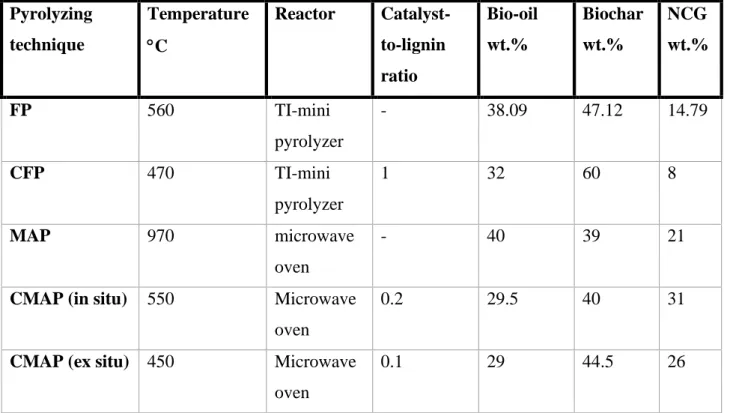
Table 5 below shows a collection of parameters and products yield obtained from various pyrolysis techniques:
Table 5. data collected from different pyrolysis techniques (17,49,50)). Pyrolyzing technique Temperature C Reactor Catalyst-to-lignin ratio Bio-oil wt.% Biochar wt.% NCG wt.% FP 560 TI-mini pyrolyzer - 38.09 47.12 14.79 CFP 470 TI-mini pyrolyzer 1 32 60 8 MAP 970 microwave oven - 40 39 21
CMAP (in situ) 550 Microwave oven
0.2 29.5 40 31
CMAP (ex situ) 450 Microwave oven
8 Result
In this chapter, results of the collected data from references (17,49,50) and calculations shown in the previous section are presented and discussed. Comparative analysis between pyrolysis methods mentioned above are discussed, energy efficiencies of various techniques are presented, and environment impacts are discussed. The error estimations for energy efficiencies are determined by using the maximum error estimation method.
8.1 Comparison of products mass yields
The comparison result shows that the highest product yield in most pyrolysis techniques is owned by biochar, followed by biooil and NCG. An exception for CMAP (ex situ) where NCG yield exceeds biooil yield.
8.1.1 Char mass yields
According to the reviewed literature of different pyrolysis techniques, it is shown that CFP (50) has the highest mass yields of biochar among other techniques with a value of 60 wt.%. The high yield of biochar in CFP is because of the low pyrolysis temperature. The uniform heat distribution offered by microwaves resulted in lower yields of biochar, this is observed in CMAP where low temperature and uniform distribution in the material support the formation of gaseous products. A representative image of biochar mass yields is shown in figure 3.
Biochar yield has the lowest value when pyrolyzed in MAP (49), this is because of the high operation temperature and the rapid heat distribution in the material. This result is agreed with other experiments of pyrolyzing biomass, it is shown that pyrolyzing corn stover by catalytic microwave-assisted pyrolysis supports the formation of gaseous products (52). As figure 3 demonstrates, biochar mass yields are decreased significantly when microwaves are used as a heating method instead of conventional heating. Table 5 shows that MAP has the highest operation temperature and lowest biochar yield among other pyrolysis techniques. Figure 3 shows that the implements of catalysts in both conventional pyrolysis and microwave-assisted pyrolysis increases biochar yields.
8.1.2 Biooil mass yields
The highest and lowest mass yields of biooil is obtained by MAP (49) and CMAP (in situ), respectively. MAP produces largest amounts of biooil among other pyrolysis techniques because of the high pyrolyzing temperature that reaches 970 C and the rapid heat distribution. Product yields of biooil obtained from different pyrolysis techniques are presented in figure 4.
Figure 4. Biooil yields from different pyrolysis techniques (17,49,50).
As demonstrated in figure 4. biooil mass yield from CMAP has the lowest values among other pyrolysis techniques with similar yields in both ex situ and in situ. Pyrolysis of lignin without catalysts results in higher yields of biooil. When comparing catalytic fast pyrolysis of lignin pyrolysis to other feedstocks pyrolysis, such as corn stover (52), it is observed that catalytic fast
pyrolysis of kraft lignin results in higher yields of syngas than biooil. The same result is observed when comparing lignin products yield distribution to products yield distribution obtained from cellulose pyrolysis (53). As shown in table 1, MAP (49) operates at very high temperatures which contributes to a brief increase in biooil yield. Implementing catalysts in conventional pyrolysis and in microwave-assisted pyrolysis decrease biooil yield by 6% and 11%, respectively.
8.1.3 Non-condensable gases mass yields
Highest yield and lowest yield of NCG are observed by pyrolyzing lignin in CMAP (ex situ) (17) and CFP, respectively. As demonstrated in figure 5, microwaves-assisted pyrolysis techniques support the formation of gaseous products since microwaves create uniformity in heat distribution. When catalysts are used in conventional heating, NCG yield is reduced by approximately 47%, this is due to rapid heating process that catalyst offer that support the formation of gaseous products. However, switching from conventional heating to microwaves assisted heating shows a significant increase in NCG yield. As table 5 illustrates, lowest pyrolysis temperature owned by CFP resulted in small values of NCG (50).
Figure 5. NCG yields from different pyrolyzing techniques (17,49,50).
8.2 Energy efficiencies of pyrolysis techniques
This section presents energy efficiencies of investigated pyrolysis techniques. Where values of equations used in the methodology part are calculated. Biochar LHV is determined to 22.15 MJ
by taking the average LHV of various biochar types produced by pyrolyzing different biomass feedstocks (47).
8.2.1 Fast pyrolysis (FP)
calculations performed in this thesis show that an energy of 0.39 MJ is required to increase lignin temperature from 100 C to the desired pyrolysis temperature which is 560 C for FP. The produced gases leave the pyrolyzer and heat is recovered by a heat exchanger or a condenser, heat recovered from biooil and NCG is calculated to 0.51 MJ. When considering Qproducts Energy offered from biochar, biooil and NCG is calculated to 6.04 MJ, 5.64 MJ and
4.66 MJ, respectively. Ultimately, these values result in an energy efficiency of 60%.
8.2.2 Catalytic fast pyrolysis (CFP)
Implementing catalysts in fast pyrolysis results in an energy efficiency of 47%, which is the lowest value offered among investigated pyrolysis techniques. Energy required to pyrolyze the lignin in CFP is calculated to 0.31 MJ where pyrolysis temperature is 470 C. Result shows that 0.28 MJ is recovered from NCG and from condensing gases into biooil. For biochar and biooil, energy offered from these two products combined is calculated to 12.6 MJ, while NCG has a value of 1.2 MJ.
8.2.3 Microwave assisted pyrolysis (MAP)
Using microwave-assisted pyrolysis requires an energy of 0.73 MJ to increase lignin temperature to 970 C. When using heat exchanger or a condenser to recover heat from produced gases, a significant amount of energy with a value of 1.81 MJ is recovered. According to calculations, energy stored in biooil and biochar combined is determined to 10.9 MJ, while NCG offers an energy value of 9.75 MJ, these values result in a value of 20.65 MJ in Qproducts.
This high energy value of NCG contributes to a considerable improvement in energy efficiency.
8.2.4 CMAP ex-situ
Based on performed calculations, CMAP ex-situ requires an energy of 0.29 MJ to achieve a pyrolysis temperature of 450 C. Based on calculations, 0.5 MJ is recovered from NCG and from condensation of biooil. Result shows that 15.7 MJ is offered form Qproducts, with a
distribution of 4.4 MJ, 5.7 MJ and 5.6 MJ in biooil, biochar and NCG, respectively. These calculated values showed a value of 61% efficiency in CMAP ex situ.
8.2.5 CMAP in-situ
The CMAP in-situ requires an energy of 0.38 MJ to achieve a temperature of 550 C. Calculations show that 0.71 MJ is recovered from NCG and biooil. Energy stored in products
and NCG, respectively. Using these values to determine energy efficiency in CMAP in situ results in a value of 62%.
8.3 Comparison between pyrolysis techniques
This section compares results obtained from calculation performed on equations shown in the previous methodology parts. This thesis assumes that 1 kg of kraft lignin with 30% moisture content is used as the input amount in the process. After drying the lignin, all moisture is removed, and the dry content is increased to 100%, therefore 0.7 kg of kraft lignin leaves the dryer and enters the pyrolyzer. For equation 14 shown in section 7.6.3, T1 is chosen to be 100
C because of assuming that lignin leaves the dryer and enter the pyrolyzer directly. Result shows that energy required to dry the lignin is the same in all pyrolysis techniques with a value 0.835 MJ, which indicates that energy required to dry the material prior pyrolysis has similar impacts on energy efficiencies in all techniques. In contrast to drying, energy required to increase temperature in the lignin feedstock during pyrolysis differ between various techniques since heat is supplied from different resources. Also, the different operation temperatures between pyrolysis techniques result in an alternation of energy required to pyrolyze the lignin. Calculations show that MAP requires an energy of 0.73 MJ to increase the lignin temperature to 970 C, meanwhile, the energy required to achieve depolymerizations temperatures is decreased by almost 50% in other pyrolysis techniques. Energy required to depolymerize the lignin in FP, CFP and CMAP (in-situ and ex-situ) did not differ significantly between these methods and an average energy value to depolymerize lignin in these four techniques is 0.35 MJ.
The heating value of kraft lignin is obtained by Lignocity with a value that varies between 25-27 MJ when combusted as a solid fuel. According to the performed calculations in this thesis, it is observed that the alternation in input energy depends on the energy required to increase the temperature in the pyrolyzer, since energy offered by lignin as a solid fuel and energy required to remove moisture content of the lignin remain unchanged throughout the process.
The output energy from all pyrolysis techniques consists of energy offered by the products and energy recovered from the produced gases. Based on calculations performed in this thesis, a considerable amount of energy is recovered from existed gases produced during MAP with a value that exceeds 1.8 MJ. The recovered heat in other techniques are decreased since gases leave the pyrolyzer at lower temperatures with an interval of 450-560 C. Also, it is observed that NCG composition has important impacts on heat recovery since heating values