SKI Report 2005:34
Research
An Applied Study on the Decontamination
and Decommissioning of the Map Tube
Facility 317 Area Argonne National
Laboratory, Chicago
Geoff Varley
Chris Rusch
January 2005
ISSN 1104–1374 ISRN SKI-R-05/34-SESKI Report 2005:34
Research
An Applied Study on the Decontamination
and Decommissioning of the Map Tube
Facility 317 Area Argonne National
Laboratory, Chicago
Geoff Varley
Chris Rusch
NAC International
32 Bell St
Henley on Thames
Henley-on-Thames RG9 2BH
Oxfordshire
UK
January 2005
SKI Project Number XXXXX
This report concerns a study which has been conducted for the Swedish Nuclear Power Inspectorate (SKI). The conclusions and viewpoints presented in the report are those of the author/authors and do not necessarily coincide with those of the SKI.
Background
The nuclear power utilities in Sweden must under the so-called “Studsvik Act”
1contribute
with 0,15 öre (approximately 0,02 European cents) per kWh produced by nuclear power to the
Swedish Nuclear Waste Fund. This part of the financing system was resolved by the Swedish
parliament for the future expenses of decontamination and decommissioning of older Swedish
research nuclear reactors and certain objects at the Studsvik site. The task to accrue
appropriate capital is based on cost estimates for decontamination and decommissioning of
individual facilities. It is therefore vital that these cost estimates are reliable, objective and
long term sustainable; otherwise there will be a discrepancy between funded capital and future
obligations. One central constraint is that a situation with a deficit in the fund must be
avoided. Consequently, it is crucial that the cost estimates for the Storage Facility for Old
Intermediate Level Waste
2at the Studsvik Site is scrutinised and validated. This validation is
done by a contemporary comparative cost. This mode of analysis may be regarded as a
consistency test of the appropriateness of the cost estimates.
Purpose of the project
The aim of this applied study has been to describe and study the basis for the estimation of
future costs for decontamination and decommissioning for the Storage Facility for Older
Intermediate Level Waste
at the Studsvik Site.
Results
This study demonstrates how a systematic comparative analysis of cost estimates can be done,
in order to increase the traceability and reliability. A comparison of the estimated future costs
for decontamination and decommission for the Storage Facility for Old Intermediate Level
Waste
at the Studsvik Site with benchmark references of the Map Tube Facility 317 Area at
the Argonne National Laboratory, Chicago, USA, was partially conducted.
The main results from the evaluation of the estimated cost for the Storage Facility for Old
Intermediate Level Waste compared with the Argonne Map Tube Facility decommissioning
costs, and other selected derived decommissioning cost benchmarks, can be presented in the
following three statements.
• The estimated costs for preparation of the project to decontaminate and dismantle the
Storage Facility for Old Intermediate Level Waste appear to be adequate.
• There seems to be some risk of cost underestimation in the project support part, which
also includes characterisation and decontamination due to e.g. uncertainty in facility
radiological condition/degree of contamination, unsophisticated definition of
contingency margins and possible implications of the preceding items for actual
1 The complete name is the Act on the Financing of the Management of Certain Radioactive Waste etc. (1988:1597).
concrete demolition technique will be acceptable.
• The comparison suggests that the cost estimates for the actual dismantling of the
Storage Facility for Old Intermediate Level Waste may be underestimated. The
estimated costs of core drilling may for example be too low. In addition, depending on
the radiological conditions discovered, the final method of demolishing the concrete
vault structure may have to change, with potentially higher costs.
The report clearly demonstrates that it is possible to enhance and extend the present
knowledge basis for cost estimates by using feedback of experience by trying to apply
benchmarking data, but a successful outcome depend every so much on the quality of the
original data.
This report shall be seen as a contribution to active learning; that may help to improve
calculations of the decontamination and decommissioning cost so that a more reliable
estimate can be presented on successive higher confidence levels.
Continued work
This study indicates that there exists a need to develop a more comprehensive platform for
how to retrieve and gather decommission cost data in a clear, and traceable manner. Review
of estimates and suggestions of how they can be more transparent gives contributions to our
understanding of the prerequisites for good cost estimations, as well how more reliable cost
estimates can be derived. But first and foremost these estimates must be based on a
comprehensive and clear method.
Effects on SKI work
SKI will be able to draw inferences from this study in the yearly monitoring of cost estimates
which are presented by the company AB SVAFO in late April every year. Thus, this study
will give support to the current review process of the estimated decommissioning and
dismantling costs of the Storage Facility for Old Intermediate Level Waste (AT).
Project information
At SKI Staffan Lindskog have been responsible to supervise and co-ordinate the project.
Geoff Varley and Chris Rusch from NAC International, England, have accomplished the
research task. Bryan McHugh was responsible for the translation of the original report into
English.
SKI
January 2005
NAC
I
NTERNATIONALAtlanta Corporate Headquarters 3930 East Jones Bridge Road Norcross, Georgia 30092 770-447-1144 Fax 770-447-1797 32 Bell St Henley on Thames Henley-on-Thames RG9 2BH Oxfordshire United Kingdom 44 1491 636 284 Fax 44 1491 413 023 2-7-10, Sakura-Machi Mail No. 184 Koganei, Tokyo, Japan 81-423-87-6758 Fax 81-423-87-6740
22/25 Bolshoi Strochenovsky Pereulok 113054 Moscow
Russia 7-095-230-6832 Fax 7-503-230-6844
227 Gateway Drive, Suite 116-B Aiken, South Carolina 29803 803-652-7413
Fax 803-652-7451
841 Blossom Hill Road; Suite 205 San Jose, CA 95123
Phone 408-229-6240 Fax 408-229-6245
Stoller Nuclear Fuel
A Division of NAC International
485 Washington Avenue Pleasantville, New York 10570 914-741-1200
Fax 914-741-2093
C-2005-01
The information contained in this report has been prepared by NAC International (NAC) based upon data obtained from sources we consider reliable and/or calculations consistent with technical principles we consider applicable. Neither NAC nor any individual author makes any warranty or representation, expressed or implied, with respect to the accuracy, completeness or usefulness of the information contained in this report, or assumes any responsibility for liability or damage that may result from the use of any information disclosed in this report.
A
BOUT THEA
UTHORSG
EOFF
V
ARLEY
Dr. Varley has more than 28 years of experience in the nuclear industry, more than 16 years as a consultant and manager with NAC and, before that, more than 12 years with U.K. nuclear fuel services company British Nuclear Fuels plc (BNFL). Since joining NAC in April 1988, Dr. Varley has applied his experience and expertise to a wide range of consulting activities, serving clients worldwide. In June 1993 he became general manager of NAC’s Zurich operations. In this capacity, he was responsible for all consulting, database and sales activities performed at NAC's European hub. In July 1996 he opened NAC’s London office and in mid-2004 he was appointed as Director of Commercial Consulting for NAC, a function that he fulfils from a base close to London.
Dr. Varley’s consulting expertise is applied to all nuclear fuel cycle sectors, with a special focus in the back end (reprocessing, plutonium and uranium recycle, waste management, spent fuel transport and decommissioning) fuel fabrication and enrichment market sectors. Since April 1988, Dr. Varley has visited numerous reactor and fuel cycle service facilities throughout the world.
C
HRIS
R
USCH
Mr. Rusch has more than 30 years of experience in the nuclear industry. In his position as a Senior Consultant, he utilises his great versatility to participate in a wide range of consulting activities, spanning all fuel cycle segments from the front end through waste management and decommissioning.
Before joining NAC, Mr. Rusch was the manager of nuclear fuel at Portland General Electric and was responsible for all phases of nuclear fuel procurement, including strategic and tactical planning, bid preparation, supplier and proposal evaluations, contract negotiation, contract administration, and economic analysis. Significant experience includes management of major projects, technical professionals (in-core fuel management and safety analysis personnel) and annual operating and capital budgets of $1 million and $25 million, respectively.
Mr. Rusch managed the procurement of nuclear fuel for a nuclear plant that consistently ranked among the top 10 plants in the United States with the lowest fuel costs. He organised and directed the evaluation and negotiation teams for the procurement of nuclear fuel fabrication services and directed a multi-department, four-year project to establish a new supplier of nuclear fuel fabrication services.
Mr. Rusch has broad utility experience as his assignments required interfacing with accounting, rates and revenues, finance, legal, power analysis and power operations departments and nuclear plant staff, including reactor engineering, licensing, quality assurance and nuclear engineering groups.
Contents
Executive Summary
1. Introduction ... 1-1
2. Argonne Map Tube Facility Description and Decommissioning
Scope 2-1
2.1 Map Tube Facility Description ... 2-1 2.1.1 Site ... 2-1 2.1.2 Area 317... 2-2 2.1.3 Map Tube Facility Description ... 2-6 2.1.4 Physical Condition... 2-10 2.1.5 Wastes Stored... 2-12 2.2 Outline of Decontamination Plan Scope ... 2-14 2.2.1 Objectives ... 2-14 2.2.2 Original Scope... 2-14 2.2.3 Final Scope ... 2-15 2.2.4 Principal Assumptions ... 2-15 2.3 Outline of Planning and Institutional Requirements ... 2-15 2.3.1 General Process... 2-15 2.3.2 Specific Process for Area 317 and the Map Tube Facility ... 2-16 2.3.3 Costs ... 2-19
3. Overall Work Program... 3-1
3.1 Program Outline ... 3-1 3.2 Decontamination and Dismantling Implementation... 3-1 3.2.1 Phase I - Map Tube Facility Characterization... 3-1 3.2.2 Phase II – Insert Lifting Devices and Seal Tubes ... 3-6 3.2.3 Phase III - Removal of Tubes By Concrete Coring... 3-8 3.3 Management of Decommissioning Wastes... 3-13 3.3.1 Dewatering ... 3-13 3.3.2 Debris Removal... 3-14 3.3.3 Core Drilling Operations ... 3-14 3.3.4 Removal of Lead from the Tubes ... 3-18 3.4 Key Cost Drivers and Sensitivities ... 3-18 3.4.1 Debris Removal... 3-19 3.4.2 Selection of Dismantlement Technology ... 3-19 3.4.3 Core Drilling Guide ... 3-20 3.4.4 Water Management during Core Drilling ... 3-21 3.4.5 Drill Rig Size... 3-21 3.4.6 Guide for the Drill Bit ... 3-21 3.4.7 Vertical Angle of Tubes ... 3-21 3.4.8 Concrete Fines ... 3-23
3.4.9 Concealed Drilling Hazards ... 3-23 3.4.10 Worn Drill Bits ... 3-24 3.4.11 Working Relationship ... 3-24
4. Map Tube Facility Decommissioning Cost Analysis ... 4-1
4.1 Program Cost Breakdowns ... 4-1 4.1.1 General ... 4-1 4.1.2 Characterization and Lifting Device Insertion ... 4-1 4.1.3 Core Drilling... 4-2 4.1.4 Waste Handling and Disposal ... 4-2 4.1.5 Productivity... 4-3 4.2 Derived Benchmarking Results ... 4-5 4.2.1 Characterization ... 4-5 4.2.2 Core Drilling... 4-5 4.2.3 Comparison with Other Benchmarking Results ... 4-6
5. Comparison of Map Tube Facility with the Studsvik AT Facility5-1
5.1 Physical Comparison ... 5-1 5.1.1 Methodology and Scope of AT Decommissioning ... 5-6 5.1.2 Methodology... 5-6 5.1.3 Waste Volumes ... 5-8 5.2 Comparison of Map Tube Costs with AT Cost Estimates ... 5-10 5.2.1 Core Drilling... 5-10 5.2.2 Characterisation and Decontamination... 5-11 5.3 Reasonableness of the AT Cost Estimate ... 5-12 5.3.1 Global Cost Breakdown... 5-12 5.3.2 Preparation Cost ... 5-13 5.3.3 Characterisation and Decontamination... 5-13 5.3.4 Actual Dismantling... 5-14 5.3.5 Use of Earlier Reference Information ... 5-15 5.3.6 Conclusions... 5-15
References
A. Equipment and Materials for Tube Dewatering ...A-1
B. Equipment and Materials for Removal of Tube Debris ...B-1
C. Sequence for Tube Core Drilling...C-1
D. Equipment and Materials for Core Drilling...D-1
Tables
Table 2-1 Tube Cap Weights ... 2-10 Table 2-2 French Drain Contamination ... 2-12 Table 2-3 Tube Contents and Associated Radiation Levels ... 2-13 Table 3-1 Waste Form and Disposition... 3-13 Table 4-1 MTF Decommissioning Cost Breakdown (US$k 1994) ... 4-1 Table 4-2 Labour Breakdown for Core Drilling (US$k 1994) ... 4-2 Table 4-3 Cost of Waste Disposal, Storage and Transportation (US$k 1994) ... 4-3 Table 4-4 Productivity (US$1994) ... 4-4 Table 5-1 Comparison of AT and MTF Storage Structure Physical Parameters
(all dimensions approximate) ... 5-4 Table 5-2 AT Waste Quantities from Cost Estimate Abstract ... 5-8 Table 5-3 AT Waste Quantities from Cost Estimate Section 9... 5-9 Table 5-4 Comparison of Table 5-2 and Table 5-3 Data... 5-9 Table 5-5 Constructed Cost for Core Drilling at AT... 5-10 Table 5-6 Constructed Cost for AT Characterisation and Decontamination... 5-11 Table 5-7 Characterisation and Decontamination Activities in the AT Cost Estimate ... 5-12 Table 5-8 Summary of AT Cost Estimate... 5-12
Figures
Figure 2-1 Site Map of Argonne National Laboratory ... 2-1 Figure 2-2 ANL Area 317 Site Plan ... 2-2 Figure 2-3 ANL Area 317 and Surrounding Area... 2-3 Figure 2-4 Overhead View of Area 317 ... 2-4 Figure 2-5 Waste Compacting Equipment... 2-5 Figure 2-6 LLW Loading ... 2-5 Figure 2-7 MTF During Construction ... 2-6 Figure 2-8 Tube Placement ... 2-7 Figure 2-9 Tube End Cap Placement During Construction... 2-8 Figure 2-10 Typical Lead Joints ... 2-9 Figure 2-11 Tubes with Caps in Place... 2-10 Figure 2-12 Vault Roof Deterioration ... 2-11 Figure 2-13 Tube Contents Located in Map Tube ... 2-13 Figure 2-14 Container with Activated Steel ... 2-14 Figure 2-15 Overhead View of Area 317/319 ... 2-18 Figure 3-1 MTF Containment Equipment ... 3-2 Figure 3-2 Underwater Camera Equipment ... 3-3 Figure 3-3 Pumping Equipment ... 3-4 Figure 3-4 Grappling Equipment ... 3-5
Figure 3-5 Grappling Equipment with Object from Tube... 3-6 Figure 3-6 Core Drilling Rig on Flatbed Truck ... 3-7 Figure 3-7 Lifting Eye Inserted in Tube... 3-7 Figure 3-8 Core Drilling Rig on Flatbed Truck ... 3-9 Figure 3-9 Tube Removal... 3-10 Figure 3-10 Tube Removal... 3-11 Figure 3-11 Tube Removal... 3-12 Figure 3-12 Core Drill with Recirculation Container in Place ... 3-15 Figure 3-13 Core Drilling Cooling System ... 3-16 Figure 3-14 Dumping Concrete Fines... 3-17 Figure 3-15 Separated Tube Section ... 3-18 Figure 3-16 Overhead Crane Over MTF ... 3-20 Figure 3-17 Core Drill Contact with Tube ... 3-22 Figure 3-18 Core Drill Contact with End Cap... 3-22 Figure 3-19 Core Drill Contact with Tube ... 3-23 Figure 3-20 Voids in Concrete... 3-24 Figure 4-1 Rate of Tube Removal ... 4-4 Figure 5-1 Location of the AT Facility at Studsvik ... 5-2 Figure 5-2 Internal Building Plan Layout for the AT Facility ... 5-3
Executive Summary
Overview
The Map Tube Facility (MTF) was a large concrete block structure constructed in 1952 at the Argonne National Laboratory site in the United States, for the purpose of storing radioactive waste. The block contained 129 storage tubes that were positioned vertically in the block during construction.
From 1952 though the early 1980s, the MTF was used to store containers of highly radioactive materials. The items stored included:
Nuclear fuel elements
Nuclear reactor components
Materials samples
Irradiated metal objects (bolts, wire, rods, etc)
Concrete-encased objects
After MTF operations were discontinued in the early 1980s, most of the materials were removed from most of the tubes.
Decontamination and decommissioning of the MTF tool place in 1994. The objective was to eliminate the radiological and chemical materials within the MTF tubes to prevent ground water and soil contamination. Once these materials were removed, the block would no longer be a source of contamination (chemical or radioactive) and could then remain in place without risk to the environment.
The decontamination scope included the following actions. 1. Mechanically clean each tube (wire brush)
2. Dewater each tube
3. Remove the debris and sludge from the bottom of each tube 4. Fill each tube with concrete
5. Remove the tubes using a core drilling technique.
Project constraints precluded the use of excavation around the facility and sectioning of the MTF block or simple demolition, which led to the use of the core drilling technique.
The cost of decommissioning the MTF was approximately $2.6 million (1994 money values). Escalating this at 2.5 percent per year to January 2005 and converting to Swedish currency at the current exchange rate (January 2005 approximately 6.2 MSEK/$) gives an equivalent cost today of MSEK 20.6.
The AT facility in Studsvik is considerably larger than the MTF facility in Argonne – between six and seven times in terms of volume but with storage tube depth somewhat less. Unlike the MTF, AT has some storage vaults in addition to storage tubes. Based on available descriptions of the nature of the wastes stored in AT and the MTF, in general terms the range of wastes appears to be somewhat similar.
In the case of the MTF it was determined that radioactive sludge was present at the bottom of the tubes, resulting from water ingress and corrosion of both storage containers and their contents. In the case of AT it is not known exactly what the condition of the tubes is but it is recognised that leakage/contamination in the lower parts of the tubes is likely to have occurred. This is an important consideration in the planning of the AT decommissioning program and the related cost estimate, principally because of the potential consequence of different approaches and specific techniques chosen to implement decommissioning.
The AT decommissioning cost estimate report is not entirely clear in detail regarding the specific methodology to be adopted. In addition there are a number of important
uncertainties concerning the extent of radioactive contamination. Depending on what the reality turns out to be, the decommissioning methodology could be affected and the quantities of wastes in various categories also could vary. In any event, the AT cost estimate report is unclear regarding waste volumes in a number of respects.
Main Conclusions
The AT cost estimate is presented in a similar fashion to several other recent decommissioning cost estimates prepared by Westinghouse for SVAFO, using an approach and presentation format that suffers somewhat from:
Not always being clear
Not always being unambiguous and easy to understand and,
Setting these concerns aside, the available information has been evaluated and compared with the Argonne MTF decommissioning costs and other selected NAC derived
decommissioning cost benchmarks.
In summary the conclusions for the AT decommissioning cost estimate are as follows:
P
REPARATIONThe AT estimate appears to be adequate.
PROJECT SUPPORT
(
INCLUDING CHARACTERISATION AND DECONTAMINATION)
Some risk of cost underestimation related to: Uncertainty in facility radiological condition/degree of contamination
Unsophisticated definition of contingency margins
Possible implications of the preceding items for actual decommissioning methodology and related costs
It appears very necessary to invest more heavily in the characterisation program to determine if the proposed concrete demolition technique will in fact be acceptable.
ACTUAL DISMANTLING
The available data and relevant comparisons suggest that the AT cost estimate for this part of the project cost may be underestimated. The estimated cost of core drilling at AT may be low. In addition, depending on the radiological conditions discovered, the final method of demolishing the concrete vault structure may have to change, with potential higher cost implications. This reinforces the very important message that comprehensive characterisation of the AT facility is required and that the methodology for subsequent decommissioning work may need to change depending on the conditions revealed by this investigative phase.
1. Introduction
Statenskärnkraftinspektion (SKI) charged NAC International with the task of conducting a study of the decommissioning activities and costs for the Map Tube Facility (317 Area) at the Argonne National Laboratory, Chicago (hereafter referred to as the MTF) in comparison with the decommissioning plan and cost estimate for the AT Storage Facility for Old Intermediate Level waste at the Studsvik Site in Sweden. The AT cost estimate is contained in report SEP 01-317 prepared by Westinghouse Atom AB for AB SVAFO. This report presents the conclusions of NAC’s analyses and comparisons. It includes a full analysis of the MTF, the derivation of relevant benchmarking results from that decommissioning program and a prudence review of the AT cost estimate, looking at the reasonableness of the cost estimate as well as the completeness of the estimate and related logistics.
2.
Argonne Map Tube Facility
Description and Decommissioning
Scope
2.1
Map Tube Facility Description
2.1.1 Site
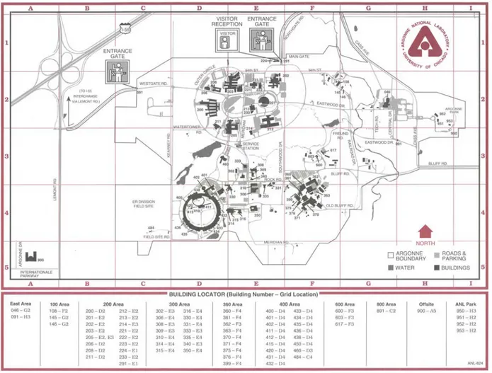
The MTF is located in the 317 Area of the Argonne National Laboratory (ANL) located about 40 kilometres from Chicago, Illinois, USA. The 317 Area is situated in the south central portion of the ANL site, see sector E5 of Figure 2-1 (Site Map of Argonne National Laboratory).
2.1.2 Area
317
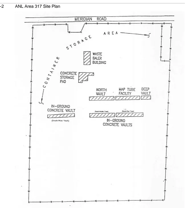
This area contained a number of facilities, including six in-ground vaults, for handling and storing radioactive waste as shown in the Area 317 site plan (Figure 2-2 and Figure 2-3) and the overhead picture of Area 317 (Figure 2-4). The MTF is located in Area 317 and is the middle facility in the north row of vaults.
Figure 2-4 Overhead View of Area 317
ANL stored low and intermediate-level (transuranic) waste in four of the vaults, the three vaults in the lower row on Figure 2-4 and the left-hand facility in the upper row on Figure 2-4. The deep vault (right-hand facility on the upper row with overhead crane above the facility [Figure 2-4]) was used exclusively to store intermediate-level
radioactive waste. Small containers of highly radioactive waste (HLW) were stored in the MTF, middle facility in the upper row on Figure 2-4.
Steel bins containing low-level radioactive waste (LLW) which were awaiting off-site disposal were stored in a gravel-covered area north of the vaults.
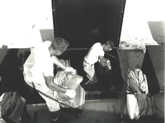
The Bailer Building was located in the 317 Area. Originally, the building was used to compact radioactive waste. This included waste compaction equipment (Figure 2-5) used in that era. Figure 2-6 shows compacted LLW being loaded into storage and transport bins. The tubes of the MTF were not designed to receive or store compacted waste.
Later, the building was used to decontaminate surface radioactivity from equipment, lead bricks and tools, using a carbon dioxide pellet blaster.
Figure 2-5 Waste Compacting Equipment
2.1.3
Map Tube Facility Description
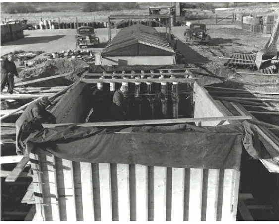
The MTF was a large concrete block structure (Figure 2-7) that was constructed in 1952 for the purpose of storing radioactive waste. The block is 4 meters wide, 8.5 meters long and 6.4 meters deep (5.8 meters of which is below grade level). The block contained 129 cast-iron, bell and spigot1 sewer pipes that were positioned vertically in the block during construction, see Figure 2-7 and Figure 2-8. Five pipes (hereafter referred to as “tubes”) were 25.4 cm in diameter, 84 tubes were 15.2 cm in diameter and 40 tubes were 10.2 cm in diameter. All tubes were the same length, approximately 6.2 meters.
Figure 2-7 MTF During Construction
1. “Bell and spigot” refers to the shape of the ends of cast-iron sewer pipes such that one pipe can fit to another pipe in a fairly tight joint.
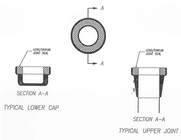
Figure 2-8 Tube Placement
A cast-iron cap (end cap) was fitted to the bottom of each tube (the end caps are shown encased in concrete during construction, Figure 2-9). A lead oakum2 seal was applied to the cap-tube joint, similar to the cast-iron sewer construction techniques of that era. Each tube also had a joint located about 0.6 meters from the top of the block (see the front row of tubes in Figure 2-7). This joint also contained a lead oakum seal. The lead oakum material represented a significant waste issue during the planning and decontamination of the MTF. Figure 2-10 depicts typical lead oakum joints.
2. “Oakum” refers to the material used to caulk seams in wooden ships. Its use here presumably is to indicate that a similar material was used to seal the lead joints of the cast-iron sewer pipes.
Figure 2-10 Typical Lead Joints
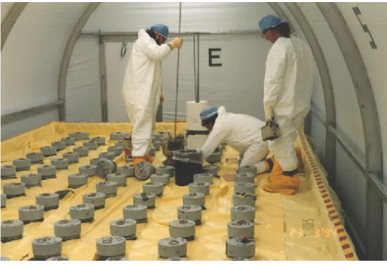
The mouth of each tube was covered with a loose-fitting lead cap approximately 15.2 cm thick. The caps are pictured in Figure 2-11. The cap weights are listed in Table 2-1.
Figure 2-11 Tubes with Caps in Place
Table 2-1 Tube Cap Weights
Tube Diameter (cm) Cap Weight (kg)
10.2 13.6
15.2 27.2
25.4 45.4
Originally, the MTF was covered with a tent-shaped, removable roof.
2.1.4 Physical
Condition
The removable MTF roof deteriorated in the late 1970s and was removed. Figure 2-12 provides a good representation of such roof deterioration over one of the LLW vaults pictured in the figure. This allowed the tubes to be exposed to the weather and became one of the principal paths for tube flooding.
Figure 2-12 Vault Roof Deterioration
In June 1989, five core holes were drilled through the base of the MTF to determine the presence of radioactivity underneath the facility. Soil and groundwater samples were collected and analysed for tritium and gamma spectrometry. Measurable levels of tritium were detected in the soil samples (0.01 to 0.31 Bq per gram) and water samples (10.85 to 4,074.1 Bq per liter).
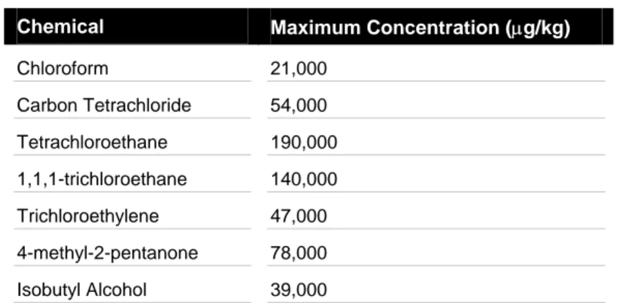
The groundwater near the MTF was contaminated with low levels of tritium, cesium-137 and strontium-90. The MTF was the suspected source of this contamination because of deterioration of the lead joints in each tube and cracks in the concrete block. In addition, the “French Drain” (see Figure 2-3) located near the MTF was contaminated with chlorinated solvents and the chemicals listed in Table 2-1.
Table 2-2 French Drain Contamination
Chemical Maximum Concentration (µg/kg)
Chloroform 21,000 Carbon Tetrachloride 54,000 Tetrachloroethane 190,000 1,1,1-trichloroethane 140,000 Trichloroethylene 47,000 4-methyl-2-pentanone 78,000 Isobutyl Alcohol 39,000
The highest levels of contaminated soil were located immediately north of the north row of waste storage vaults, see the “French Drain” designated area on Figure 2-3. That is, the contaminated soil was very close to the MTF. The presence of these chemicals had a significant impact on the technology selected for the MTF decontamination project, see section 3.4.1.
2.1.5 Wastes
Stored
During 1952 though the early 1980s, the MTF was used to store highly radioactive materials placed in metal containers that were similar to the containers used to store maps and drawings, hence the name of the facility. Some of the materials were re-inserted into ANL research reactors for additional irradiation at different times and so the materials had to be easily retrievable. The items stored included:
Nuclear fuel elements
Nuclear reactor components
Materials samples
Irradiated metal objects (bolts, wire, rods, etc)
Concrete-encased object
Figure 2-13 provides an example of the contents of a tube. At least nine tubes contained debris which ranged in weight from the weight of a paperclip up to 23 kgs. Table 2-3 lists the contents and radiation level in the tubes that contained debris.
Figure 2-13 Tube Contents Located in Map Tube
Table 2-3 Tube Contents and Associated Radiation Levels
Tube ID Diam
(cm)
Maximum Dosea
(mSv per hour)
Description
A3 25.4 < 0.002 Metallic object buried in sediment A5 25.4 < 0.002 76 cm long metal rod
D11 15.2 200 2 tubes and several wire-like objects D12 15.2 < 0.002 Small rod (0.32 cm diam x 30.5 cm) J10 15.2 0.06 12.7 cm diam metal tube cap J12 15.2 500 15 tubes (61 cm long x 1.3 cm diam) M12 15.2 400 Hexagonal tube with rods (91 cm long) Q18 10.2 0.002 Metallic wire or clip (5 cm long) R20 10.2 4 Concrete plug at bottom of tube
a. Near or on contact with an object
After MTF operations were discontinued in the early 1980s, most of the materials were removed from most of the tubes.
At the time of the characterization of the MTF in 1993, there was still some wire, bolts and an object that looked like an experimental breeder reactor (EBR) fuel assembly located in the tubes. The object (Figure 2-14) that looked like an EBR blanket assembly turned out to be a container with activated steel rods.
Figure 2-14 Container with Activated Steel
The most significant radioactive source in the tubes at the time of the 1993 characterization was the sludge at the bottom of the tubes consisting of corrosion products from metallic corrosion of the containers and contents and the radioactive contamination left after storing materials in the tubes.
2.2
Outline of Decontamination Plan Scope
2.2.1 Objectives
The objective of the MTF decontamination was to eliminate the radiological and
chemical materials within the MTF tubes to prevent ground water and soil contamination. Once these materials were removed, the block would no longer be a source of
contamination, chemical or radioactive, and could then remain in place without risk to the environment.
2.2.2 Original
Scope
The original decontamination scope included the following actions. 1. Mechanically clean each tube (wire brush)
2. Dewater each tube
4. Fill each tube with concrete
5. Remove only the tubes (less than ten tubes) with the highest radiation levels
2.2.3 Final
Scope
The funding for the decontamination of the facility was awarded incrementally. The original funding level permitted the scope of work outlined in section 2.2.2. Thereafter, on three or four occasions, new funding was assigned to the project after ANL
management evaluated the project. With each new funding increment, it was decided to increase the number of tubes to be removed. Eventually, this lead to funding for the removal of all 129 tubes.
2.2.4 Principal
Assumptions
Evidence of flooding in the tubes indicated the possibility of ground water intrusion. Given this possibility and the known contents of the tubes, the assumption was made that if ground water was entering the tubes, contaminants could be exiting the tubes and mixing with the outside ground water.
2.3
Outline of Planning and Institutional
Requirements
2.3.1 General
Process
ANL is a multiprogram research and development laboratory mostly funded by the U.S. Department of Energy (DOE). The resultant waste streams of some of the programs conducted at ANL include highly radioactive waste and chemically hazardous waste. No waste is currently disposed of on-site but, in the past, Area 317 was used as an interim storage site.
In the late 1980s, ANL began a program to locate, characterize and clean up waste sites. In 1987, ANL produced a Preliminary Assessment Report that identified 13 sites at ANL with known or suspected hazardous substances.
In December 1990, ANL applied for a Part B Permit under the Resource Conservation and Recovery Act 3(RCRA). This application triggered the Corrective Action provision of RCRA (Section 3004[u]). Based on the corrective action requirements, the Illinois Environmental Protection Agency (IEPA) conducted a RCRA Facility Assessment which identified 735 solid waste management units (SWMU) and five areas of concern. The list of SWMUs includes wastewater holding tanks, sumps, sewer lines, sludge beds, loading docks used to store waste, recycled materials staging areas, satellite accumulation areas and land disposal units. MTF was designated SWMU No. 12.
The first step after the assessment was to evaluate the 735 SWMUs against five areas of concern to determine those that require further action. It was determined that
approximately 600 SWMUs should qualify for “no further action” status. The MTF was one of 71 SWMUs that definitely required further action.
Once a SMWU is designated for further actions the process is as follows: 1. Complete a characterization phase RCRA Facility Investigation (RFI). 2. Compile the Corrective Measures Study (CMS) that involves developing and
evaluating several technologies for facility remediation. The regulatory agency selects the technology to be used.
3. The selected technology is then implemented during the Corrective Measures Implementation stage.
2.3.2
Specific Process for Area 317 and the Map Tube Facility
The clean up efforts are and were funded by the DOE Environmental Management Program. The three-step process above was identified as potentially very expensive and inefficient requiring many years for all 71 SWMUs that required action. As a result DOE encouraged interim actions and expedited remedial actions at DOE facilities.
3. The Resource Conservation and Recovery Act (RCRA) was enacted in 1976 as an amendment to the Solid Waste Disposal Act of 1965. It was later amended in 1986. RCRA is a combination of the first solid waste statutes and all subsequent amendments. RCRA authorizes EPA [U.S. Environmental Protection Agency] to regulate solid waste management activities. RCRA authorizes states to develop and enforce their own waste management programs, in lieu of the federal program, if a state's waste management program is substantially equivalent to, consistent with, and no less stringent than the federal program.
ANL began an environmental restoration program (ERP) that maximizes the potential for interim actions by proceeding with some clean-up work before the CMS is completed. The result is that the costs for conducting the RFI, characterization, evaluating
technologies and preparing the CMS report are significantly reduced. Costs are also reduced because escalating decommissioning and waste disposal costs are avoided. Initiating interim actions also minimizes the potential for a spread of contamination, which in turn reduces future costs.
ANL characterisation of the 71 SWMUs was used to identify the sites with the highest potential risk (human health or environmental risk as well as magnitude and nature of contaminated areas) and greatest economic liability. Two areas, area 317/319/ENE and area 800 met the risk and economic liability criteria for high priority action as determined by both DOE and ANL. The necessary funding was provided for interim remedial action. The interim remedial action strategy uses available information including recent and historic aerial photographs (for MTF see Figure 2-4 and Figure 2-15), employee interviews, routine environmental monitoring information, compliance monitoring of surface and ground water, preliminary characterization radiological surveys, site closure sampling, and facility design information. The report “Design Memorandum for the Decontamination of the ANL 317 Area Map Tube Facility” (ANL-AT-0004) contains this information for the MTF.
Figure 2-15 Overhead View of Area 317/319
Specific site characterization was conducted. For Area 317, the characterization process was reported in, “ANL Area 317 Phase I & II Characterization Report” (ANL-TR-0001). The process of evaluating SWMUs within the 317/319/ENE and 800 areas included evaluating interim actions for those SWMUs that have
1. significant contamination, and
2. interim clean up costs that meet budget constraints.
It was determined that the MTF met these criteria and an interim remedial action (decommissioning) was authorized.
In summary, the RCRA provides a complicated formal process for site remediation. In order to expedite site clean up while the RCRA process is pending, interim clean up measures were instituted by DOE. The MTF decommissioning project constituted one of many interim cleanup measures conducted at ANL.
2.3.3 Costs
Because the MTF decommissioning program initially was part of a much bigger national effort to identify and characterise facilities and sites for decommissioning, it would not be straightforward to attribute planning and other institutional costs/resources needed specifically for the MTF. These unique circumstances in the U.S. indeed most likely would lead to a result that would not be meaningful in the context of the Studsvik AT storage facility. Accordingly a comparison of planning and institutional costs for the AT and MTF facilities is not attempted in this report.
3.
Overall Work Program
3.1 Program
Outline
The work scope included the following phases:
Phase I - Characterization of the MTF tubes 1. Measure surface radiation levels
2. Underwater camera survey for tubes with high radiation levels 3. Brush tubes
4. High-pressure water spray the interior of tubes 5. Dewater tubes
6. Removal of sediment and debris
Phase II - Seal the Tubes and Install Tube Lifting Devices 1. Insert the lifting device in each tube
2. Seal the tube by grouting the lifting device in place with concrete
Phase III - Removal of Tubes By Concrete Coring
1. Concrete coring of tubes with conventional vertical concrete coring rig 2. Remove concrete core from the MTF block
3. Remove tube end caps and upper joint sections of the cored tube 4. Remove lead joints from the joint sections in No. 6 above
5. Wrap the core sections with plastic sheeting in preparation for shipment 6. Load the core sections onto a flat-bed truck for transport
7. Transport cored sections to a LLW site for burial
3.2
Decontamination and Dismantling
Implementation
3.2.1
Phase I - Map Tube Facility Characterization
3.2.1.1 Dewatering
Process
During a six-week period from late 1993 to early 1994, the Energy Technology Engineering Center, Rocketdyne Division of Rockwell International1 (ETEC) characterized the MTF. The first phase of the characterization was to assemble a temporary tent-type structure over the MTF, as shown in Figure 3-1. This provided two functions, airborne radiation containment and protection from the elements.
Figure 3-1 MTF Containment Equipment
The surface radiation levels of all 129 tubes were measured. Virtually all tubes exhibited smearable contamination. Twenty-seven of the tubes were contaminated enough to generate elevated radiation levels within the tubes. General exposure rates in the tubes ranged from zero to 6 mSv per hour. Nine tubes contained debris and the highest exposure rate in one tube reached 500 mSv per hour near the debris, see Table 2-3. The tubes with the highest radiation levels were inspected with an underwater camera (Figure 3-2) to determine the contents of the tubes. Highly radioactive materials were discovered in six tubes; however, several tubes with high radiation readings did not contain objects. These tubes had contained radioactive objects that were withdrawn earlier but not before the objects had spread contamination in the tubes.
Figure 3-2 Underwater Camera Equipment
For the tubes with high radiation levels, underwater dose rates were measured and surface (smear) and water samples were collected. Tritium levels in the water samples ranged from 0.59 to 638.74 Bq per millilitre. The smear samples were analysed for cesium-137 and cobalt-60 and had concentrations from 0.0048 to 23.96 Bq per smear. The sediment also contained lead in excess of the RCRA toxicity limit of 5 mg per liter, meaning that it would have to be handled as a mixed waste.
ANL did not have a permit to treat mixed waste so a two-stage water removal process was performed. The water in each tube was pumped down to a depth of about 46 cm (Figure 3-3) into a 3,400-liter tank. The water in this tank was evaporated with on-site ANL liquid evaporation equipment.
Figure 3-3 Pumping Equipment
Each tube that did not contain debris was rinsed with a high-pressure water jet, scrubbed with a stiff bristle wire brush (Figure 2-11) and rinsed again with the high-pressure water jet. The residual water and sediment was pumped into three, 208 liter galvanized steel drums (Figure 2-12). An approved absorbent material was added to the drums which were then moved to an on-site mixed waste facility.
The rinse and scrub process was repeated until contamination had been reduced to an acceptable level. In addition, following debris removal, the process described above was conducted on the respective tubes.
The dewatering procedure worked well and equipment problems were minor which allowed this phase to be completed ahead of schedule. The dose rates at the filters did not exceed 0.40 mSv per hour which was attributed to the two-stage dewatering process. That is, removal of the water down to 46 cm above the bottom of each tube and then pumping the sediment and remaining water into steel drums. The sock filters located in “quick change” housings permitted a change of filter without interrupting pumping operations. The equipment and materials required for dewatering the tubes are listed in Appendix A.
3.2.1.2 Debris
Removal
The task of debris removal posed many unique challenges. Each tube with debris had the potential for problems with spreading contamination with activity and doses as
summarized in Table 2-3.
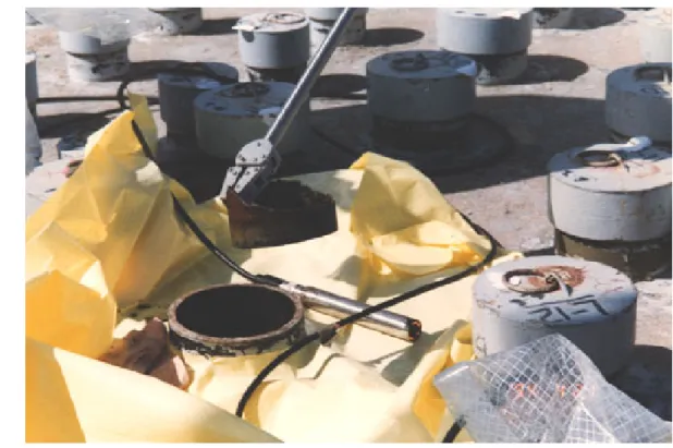
The debris was handled with long-reach grappling tools (Figure 2-14, Figure 3-4 and Figure 3-5) that could grip, snare, or scoop a variety of objects. In order to minimize exposure, significant dry run and mock-up training was conducted. Three different handling procedures were defined for debris
1. < 1.0 mSv per hour,
2. equal to or > 1.0 mSv per hour and a dose assessment determined that the debris could be handled without using a transfer cask
3. equal to or > 1.0 mSv per hour and a dose assessment determined that the debris had to be handled with a transfer cask
Figure 3-5 Grappling Equipment with Object from Tube
For category (1), the debris was removed from the tubes and handled by personnel on the ground using a 1.8-meter grapple (Figure 3-5) and inserted in a shielded transfer/storage canister (a typical canister is shown in Figure 3-6). For categories (2) and (3), the debris was withdrawn using long-reach grapple equipment that was handled by personnel from the top of a man-lift. The equipment and materials required for dewatering the tubes are listed in Appendix B.
3.2.2
Phase II – Insert Lifting Devices and Seal Tubes
The lifting device consisted of a 6.1 meter long piece of #4 rebar with a 4.6 meter long 1.3 cm wire rope attached to the rebar. The wire rope had a lifting eye at one end. This assembly was inserted into each tube with the lifting eye positioned at the top of each tube (Figure 3-7) and sealed in place with concrete. This process
1. Provided a lifting mechanism for removing the concrete core, 2. Sealed the tube so that water could not enter or exit the tube 3. Added strength to the fragile cast-iron tube
Figure 3-6 Core Drilling Rig on Flatbed Truck
Figure 3-7 Lifting Eye Inserted in Tube
The sealing function was particularly important because there could be a number of weeks or months between the time that the concrete was poured to secure the lifting
device and the actual removal of the tube. In addition, as mentioned in section 2.2.3, the funding for the project was incremental and, at different times during the project, there was the potential that only a fraction of the tubes would be removed. Therefore, the sealing function also was required to prevent the spread of contamination for a considerable period of time.
3.2.3
Phase III - Removal of Tubes By Concrete Coring
Core drilling proved to be the most challenging and difficult phase of the project. The tube core drilling sequence is provided in Appendix C and Appendix D contains a list of the equipment and materials required for the drilling operation.
Problems associated with drill equipment were, in general, quickly solved. Problems unique to the MTF required more time.
Technical delays were caused by:
1. Vertical misalignment of the tubes
2. Separation of end caps due to drilling-induced vibration 3. Loss of cooling water
4. Jamming of the drill bit due to inconsistencies in the concrete 5. Foreign objects in the block
Other delays were caused by weather and weather warnings and the need to allow ANL personnel access to the vaults adjacent to the MTF.
The core-drilling rig was mounted on a flatbed truck (Figure 3-8) so that the equipment could be moved when access to the deep or north vaults was required. The flat bed truck dimensions from the end of the truck to the rear axle (Figure 3-8) were adequate to allow the drill rig to be positioned over every tube in the block.
Figure 3-8 Core Drilling Rig on Flatbed Truck
The most highly contaminated tubes were removed first. The coring operation was performed with one continuous cutting operation through 6.4 meters of concrete. Coring operations for nine tubes had to be abandoned and restarted either due to (1) loss of cooling water, (2) difficulty with foreign objects in the concrete, or (3) concrete integrity. In these cases, fresh concrete was injected into in the cuts and the coring was restarted after the concrete had cured.
Upon completion of the coring operation, where possible the core was removed
immediately (Figure 3-9, Figure 3-10 and Figure 3-11). In some instances, cores were left in place for a period subject to crane availability for removing the cores and the shipment schedule for transferring the cores to the Hanford LLW site.
Figure 3-11 Tube Removal
3.2.3.1 Coring
Experiences
With the exception of hitting the end caps, the positioning of the drill rig in general was very successful. Only three tubes were penetrated during the coring operations.
While the offsetting technique (see section 3.4.5) was used to account for the vertical misalignment of the tubes, still 34 end caps were hit by the drill during the coring
process. In four cases, both the lead joint and radioactive contamination were exposed. In one case, only the lead was exposed.
Due to vibration of the tubes induced from the drilling process, the end caps of five tubes remained in the block when the tube was pulled. Three concrete cores below the end caps also remained in the hole after the tube was removed. The caps and related concrete cores were removed using grappling devices similar to those used to remove large pieces of
debris from the tubes. Two of the five end caps that remained in the block required considerable time for removal, one required three hours and one four hours to remove the cap and associated concrete.
Tube R20 contained a radioactive object that was encased in concrete. The radiation levels on the exterior of the cored tube was 2.8 mSv per hour. The tube was cut approximately 1.4 meters from the bottom and covered with lead blankets. It was then moved to a hot cell for examination.
3.3
Management of Decommissioning Wastes
There were several types of waste generated from the project. Table 3-1 summarizes the wastes and associated quantities. A detailed description of the waste management situation applicable to each waste source is presented following Table 3-1.
Table 3-1 Waste Form and Disposition
Source Waste Type Form Quantity Disposition
Dewatering Mixed Sludge 420 liters Shipped to Hanford Dewatering LLW Water 11,360 liters Evaporated @ ANL Debris Removal LLW Metal 79 kgs Shipped to Hanford
Drilling LLW Concrete & steel 129 cores (85 cu. metres) Shipped to Hanford in 10 campaigns between 11 August and 27 October, 1994 Drilling LLW Concrete
fines 38 cu. metres Shipped to Hanford
Drilling No activity
Concrete
fines 23 cu. metres
Disposed @ ANL on-site
Drilling Mixed
Lead shield
caps ~3,060 kgs Shipped to Hanford Lead Seal
Removal Mixed
Lead from joints
~820 kgs & 0.6
cu. metres Shipped to Hanford
3.3.1 Dewatering
The effort to minimize radioactive waste during the dewatering activity was very
successful because of a two-step procedure, see section 3.2.1.1. As indicated, over 11,000 litres of water were pumped to a holding tank and eventually evaporated with no cost for radioactive disposal. A filtration system prevented particles greater than one micron from being pumped into the holding tank.
The sludge was pumped into three 208-litre drums and allowed to settle, after which the water was decanted (poured-off without disturbing the sediment). This water was also transferred to the holding tank and evaporated with the inventory above.
Sludge from the dewatering process was treated with moisture absorbent material to dry the material prior to packaging in steel drums along with other mixed waste, including small tools and materials.
All of the mixed waste was shipped to the DOE Hanford facility for storage or disposal.
3.3.2 Debris
Removal
The metal objects retrieved from the tubes were packaged and shipped to a LLW facility. One object (the concrete-encased object in tube R20) had to be inspected in the ANL hot cells before sentencing.
3.3.3
Core Drilling Operations
A schedule was established to remove the most highly contaminated tubes in descending order. Due to the questionable structural integrity of the tube joints, the decision was made to remove the entire tube plus several centimetres of the surrounding concrete. In a conventional concrete core drilling operation, water is used to both cool the drill bit and flush the concrete fines from the cut. The water is then uncontained as it runs from the cut. With the MTF drilling operation, the water had to be contained after cooling and flushing to ensure that the water was not contaminated; therefore, the quantity of water had to be minimized.
A special water recirculation container that mounted over the tube being drilled (Figure 3-12 and Figure 3-13) had to be designed to direct the water to a 570 litre tank for buffer storage and then recirculation. The fines would settle in this tank but as the concentration of fines increased, cooling efficiency decreased. As a result, the water in the storage container had to be changed (the water with fines was pumped to a separate holding tank and fresh water injected into the recirculation tank). The water had to be changed two to three times during the coring operation for one tube.
Figure 3-13 Core Drilling Cooling System
After the coring operation for a tube was complete, radiological analysis of the cooling water indicated if the tube had been breached during the drilling process. If the tube was not breached, the water would be pumped into a large storage container where the fines would settle and the water could then be recirculated. If a tube was breached, the water with fines was pumped into drums for disposal as contaminated LLW.
3.3.3.1
Non-contaminated Concrete Fines
The concrete fines were dense and difficult to handle and could not be handled with conventional equipment. In addition, the quantity was underestimated. The concrete fines sludge was scooped from the large container into a dump truck and transported to the on-site disposal area (Figure 3-14).
Figure 3-14 Dumping Concrete Fines
Originally, the plan was to use the non-contaminated fines to fill the voids in the block following removal of a tube. However, this was not possible because the fines formed a thick paste that could not be pumped.
3.3.3.2
Contaminated Concrete Fines
The concrete fines that were contaminated barely reached the radioactive content
threshold for classification as LLW; however, the fines were packed into steel drums and shipped to the Hanford LLW disposal facility. The source of the contamination was believed to be in the top 0.5 metres of the block and resulted from waste handling operations in Area 317.
3.3.3.3 Lead
Caps
The lead caps were painted in 1988 to fix radiological contamination on each cap. Initial surveys indicated levels of surface contamination below DOE criteria. However, it was uncertain if the paint contained alpha contamination and so the caps could not be released unless the paint was removed. The options for removing the paint (chemical and
mechanical) proved to be more expensive than just disposing of the caps as mixed waste, which is the option that was selected.
3.3.4
Removal of Lead from the Tubes
A significant effort was expended to reduce the volume of this waste because of the difficulty of disposing of radioactive mixed waste. The effort resulted in a 99 percent reduction in the volume of mixed radioactive waste with total waste disposal costs reduced by about two-thirds.
After the tubes were removed, it was necessary to remove the lead oakum seals so that the entire volume of the cored tubes would not be classified as radioactive mixed waste. The tube end was positioned in a small containment with a HEPA filter and the end cap and associated concrete were separated from the tube with chipping hammers, jack hammers or concrete saws. In addition, approximately the top 0.6 meters of the tube (see Figure 3-15) was separated from the tube. With the lead joints exposed, the lead was easily removed with a handheld electric hammer. The lead was placed in steel drums for shipment to the Hanford facility.
Figure 3-15 Separated Tube Section
After the end caps and top portion of the tubes were removed, the tubes were wrapped with three layers of 0.03 cm thick, nylon-reinforced plastic sheeting.
3.4.1 Debris
Removal
The success of the debris removal was directly attributed to the experience of the personnel who were familiar with the design and use of remote tooling.
3.4.2
Selection of Dismantlement Technology
Three constraints were key in determining the dismantlement technology used at the MTF.
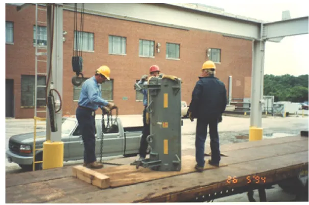
First, at the time of the dismantlement of the MTF, there were radioactive waste storage facilities that were still operating in Area 317. Specifically, two of these facilities were the deep vault and the north vault, which were located in-line with the MTF (see Figure 2-2 and Figure 2-3 and Figure 3-16). Tracks that allowed access via an overhead crane ran along either side of these three facilities. The overhead crane in Figure 3-16 is positioned over the MTF. It was necessary for the overhead crane to have access to the vaults on either side of the MTF; therefore, the technology used to dismantle the MTF had to allow this operational flexibility.
Second, regarding the chemical contamination of the soil immediately to the north of the MTF (as discussed in section 2.1.4), excavation around the MTF (Figure 2-7 provides a good indication of the excavation during construction) followed by sectioning the MTF with a diamond wire saw2 would have been easier than tube removal. However, such excavation around the MTF would have exposed personnel to significant chemical contamination and would have created a mixed waste disposal problem.
2. Diamond wire cutting is a well-tested technology for segmenting concrete blocks in decommissioning projects. A diamond wire saw consists of a diamond-impregnated wire that rotates around circular wheels (guides) similar to a band saw. As with core drilling, significant quantities of water are used to provide cooling and to flush concrete fines from the cut. In decommissioning projects, such water must be managed because of potential contamination.
Figure 3-16 Overhead Crane Over MTF
In addition, excavation near the deep and north vaults would have changed the loads on their respective walls and affected the structural strength of those facilities. The north vault was only 3 meters deep and excavation would have undermined its foundation. Third, the incremental funding of the entire project (see section 2.2.3) required a technology that could incrementally dismantle the MTF tubes.
Any of these three project constraints precluded the use of excavation and sectioning of the MTF block or demolition. By using a mobile drill rig mounted on a flatbed truck (Figure 3-8), the drilling operation could be interrupted with minimal impact on the MTF dismantlement.
3.4.3
Core Drilling Guide
First, starting a cut in the exact location desired is difficult without a guide. One solution is to use the diameter of a tube as a guide but this was not possible because both lead joints on each tube extended beyond the nominal pipe diameter (Figure 2-10) hence an over-sized drill bit and an associated guide were required.
3.4.4
Water Management during Core Drilling
Section 3.3.2 discussed the requirement for a cooling water containment and recirculation system for the concrete core drilling operation. This system was only required because of the possibility of breaching a tube and introducing LLW into the cooling water. In most concrete drilling projects is used on a once-through basis, so the water recirculating system may be considered as a special provision with associated additional costs.
3.4.5
Drill Rig Size
The initial core-drilling rig selected was too light to withstand the stress of coring through 6.4 meters of concrete. Considerable wobble was experienced and it became apparent very early in the drilling phase that a more substantial drill rig would be required.
3.4.6
Guide for the Drill Bit
A special nylon guide (see “Core Drill Guide” on figure 5) was designed to keep the drill bit in the exact position required because the drill rig would be positioned off-centre with respect to the tube opening, see section 3.4.5. Along with the water recirculating system, this was also a unique design for this project. Typically, in core drilling, the core size itself will provide the template or guide for drilling. Due to the need to compensate for the off-centre position of the tubes, a unique guide had to be devised to keep the drill located in the proper position with respect to the angle of each tube.
3.4.7
Vertical Angle of Tubes
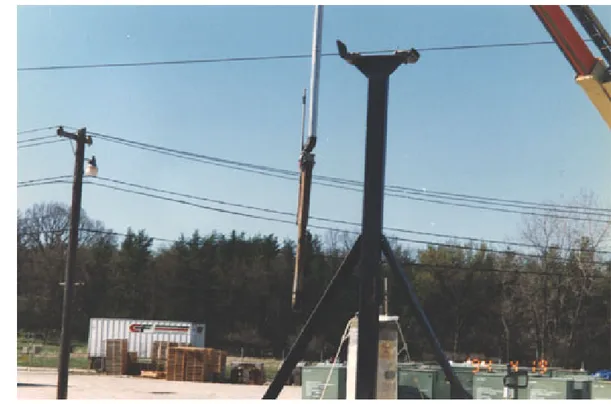
The tubes were essentially vertical when the MTF was constructed, see Figure 2-7. However, forces from concrete pouring, shifting and settling, etc caused the tubes to become off-vertical by as much as 10 cm. When drilling operations first began, there was some trial and error associated with compensating for the fact that the tubes were at a slight angle. It was very important to compensate for this situation because the drill could contact the cast-iron tube (see Figure 3-17, Figure 3-18 & Figure 3-19) and thereby release contaminated material.
Figure 3-17 Core Drill Contact with Tube
Figure 3-19 Core Drill Contact with Tube
At first, the drill rig was tilted slightly to compensate but maintaining the rig at an off-vertical angle while drilling proved impossible. Drilling at an angle accentuated the normal drift of the rig. Finally, the solution was to determine the location of the bottom of the tube with respect to the tube opening, i.e. determine the angle and direction of the tube as it descended into the MTF block. With this information, the drill rig was
positioned off-centre with respect to the tube opening. This compensation technique proved to be successful.
3.4.8 Concrete
Fines
The concrete fines (sludge) were dense and difficult to handle and conventional waste haulers would not handle this material. In addition, the quantity was underestimated.
3.4.9
Concealed Drilling Hazards
Concealed hazards caused some drilling delays. In some locations bad concrete (loose concrete) occurred around the storage tubes. Upon reaching a zone with loose concrete the drill bit would stick. Several tubes required concrete to be injected or poured into the area to bind loose concrete before drilling could continue.
Voids (Figure 3-20), cracks and other defects including objects (pipes, wood, cabs, etc) that were buried in the concrete caused a loss of cooling water. Again, concrete would be injected or poured into the offending location and allowed to solidify before coring could continue.
3.4.10
Worn Drill Bits
Two sizes of drill bits were used during the coring operations. A 45.7 cm (diameter) drill bit was used for the 25.4 cm diameter tubes and a 35.6 cm (diameter) drill bit was used for the 10.2 and 15.2 cm (diameter) tubes. Nominally, four to five tubes could be drilled before replacing a drill bit. However, a drill bit could be rendered useless after only a few meters of cutting if foreign objects in the concrete were contacted. The turn around time for refurbishing a drill bit was three days and so three of the 35.6 cm (diameter) drill bits were utilized, which allowed two spares to be on-site at all times. Since there were only five 25.4 cm (diameter) tubes, only two of the 45.7 cm (diameter) drill bits were used.
Figure 3-20 Voids in Concrete
3.4.11 Working
Relationship
Reference 1 specifically mentions that the good working relationship between the main subcontractor and the ANL project and technical personnel proved extremely helpful in
providing rapid turn around of radiological and chemical data, which in turn allowed rapid implementation of action plans.
4.
Map Tube Facility Decommissioning
Cost Analysis
4.1
Program Cost Breakdowns
4.1.1 General
The cost of decommissioning the MTF was approximately $2.6 million. This cost as well as the other costs in this section 4.0 are stated in terms of 1994 U.S. dollars. The
discussion below provides estimates of the breakdown of this cost. The major cost breakdown is presented in Table 4-1.
As explained in section 2.3, the MTF was one of 735 SMWUs to undergo preliminary evaluation by ANL and one of 71 SWMUs that was evaluated in more detail by ANL, making the cost of planning and institutional effort not relevant to the AT facility. Accordingly the cost of the planning process conducted by ANL is excluded from the data in Table 4-1.
Table 4-1 MTF Decommissioning Cost Breakdown (US$k 1994)
Category U.S. $k
Primary Contractor – ETEC (including concrete drilling subcontractor) 1,800.0 MTF Characterization - ETEC 200.0 Radioactive Waste Disposal @ Hanford LLW disposal facility 200.0
Lead Cap Disposal 16.0
Waste Transportation 84.0
ANL Supervision 100.0
Other 200.0
Total 2,600.00
4.1.2
Characterization and Lifting Device Insertion
Sections 3.2.1 and 3.2.2 outline the scope of work. ETEC, performed the work. The total cost was about $200,000. The majority of the characterization costs, $146,900, are attributed to the equipment and materials listed in Appendices A and B.
The site characterization required six weeks to complete or 1,440 hours of direct labour estimated to cost about $53,100. Management, supervision and technical support from ETEC both off and on-site cost about $26,700 and ANL supervision cost about $12,500.
4.1.3
Core Drilling
Section 3.2.2 outlines the core drilling scope of work. The primary contractor was ETEC. The total ETEC contract was for $2 million; therefore, after subtracting the cost of characterization, the cost of drilling operations was about $1.8 million.
The lifting device and core drilling phases required about 6.5 months to complete. The labour breakdown is presented in Table 4-2.
Table 4-2 Labour Breakdown for Core Drilling (US$k 1994)
Category Man-
Hours
U.S. $k
ETEC Program Manager (2/3 of the time for 6.5 months) 747 43.33 ETEC Technical Manager (1/3 of the time for 6.5 months) 373 18.06 ETEC On-site Supervisor (full time for 6.5 months) 1,120 54.17 ETEC On-site Lead Technician (full time for 6.5 months) 1,120 54.17 Direct Labour – 113, 10-hour day shifts (3 ETEC technicians @
$30 /hour, 2 drilling operators @ $30/hour and 2 health physicists
@ $20/hour) 7,910 214.70
Direct Labour – 61, 10-hour night shifts (2 ETEC technicians @ $30/hour, 2 drilling operators @ $30/hour and 1 health physicist
@ $20/hour) 3,050 85.40
Direct Labour for holidays (3) and lost time (22 days) both @ 8
hours per day 1,856 50.96
Total Contractor and Subcontractor Labour 520.79
ANL supervision (3 staff 1/3 of the time) 1,120 54.17
The equipment and materials for the core-drilling phase (Appendix D) represent the remaining cost of $1.27921 million.
4.1.4
Waste Handling and Disposal
Section 3.3 and Table 3-1 provide detailed information regarding the disposition of the waste forms generated from the MTF decommissioning project. Table 4-3 provides the cost breakdown for waste disposal, storage and transportation.