Doctoral Thesis in Fibre and Polymer Science
Degradable copolymers in additive
manufacturing: controlled fabrication
of pliable scaffolds
ASTRID AHLINDER
Stockholm, Sweden 2021
kth royal institute of technology
Degradable copolymers in additive
manufacturing: controlled fabrication
of pliable scaffolds
ASTRID AHLINDER
Doctoral Thesis in Fibre and Polymer Science KTH Royal Institute of Technology
Stockholm, Sweden 2021
Academic Dissertation which, with due permission of the KTH Royal Institute of Technology, is submitted for public defence for the Degree of Doctor of Philosophy on Friday the 26th of March 2021, at 10.00 am in Kollegiesalen, KTH, Brinellvägen 8, Stockholm.
© Astrid Ahlinder Paper I © 2018 Elsevier Paper II © 2020 Elsevier
Paper III © 2020 John Wiley & Sons, Inc.
Paper IV © 2020 American Chemical Society (ACS) Paper V © 2020 Elsevier
ISBN: 978-91-7873-778-9 TRITA-CBH-FOU-2021:7
To Jens, friends, family and colleagues.
Abstract
In tissue engineering, the production of well-defined scaffolds with a porous architecture from degradable polymers is of great interest. Detailed designs have become feasible through the development of additive manufacturing. A small nozzle size is needed to obtain detailed scaffold structures, and careful control of the rheological properties is therefore required during production. A lower viscosity of the melt allows for easier printability, but a high molar mass is required to produce scaffolds that can retain mechanical properties over the time needed for tissue regeneration. An additional challenge of using degradable polymers with high molar mass in any melt-based processing is that thermal degradation can reduce the molar mass during the production stage. To utilise medical grade degradable polymers whilst limiting the thermal degradation a rheological analysis of the most commonly used commercial medical-grade degradable synthetic polymers was performed. Their rheological behaviours aided in setting process parameters for two different melt-based additive manufacturing routes. The variation in thermal degradation in the two routes was assessed, and the parameters were adjusted to minimise it.
A nondegradative additive manufacturing method was designed, and knowledge regarding printability was developed based on rheological analysis and polymer characterisation methods. This knowledge was applied to the copolymer poly(-caprolactone-co-p-dioxanone) developed within the group to fabricate pliable scaffolds for tissue engineering with an increased rate of hydrolysis in comparison to poly(-caprolactone). In addition to the selection of the polymer and process parameters, the mechanical properties were also controlled through the structural design. Poly(-caprolactone) was used as a model material to show how the mechanical properties of scaffolds could be controlled based on the design solely. The results showed that the stiffness could be reduced by more than a factor of 10 through tuning of the design, resulting in soft pliable scaffold structures.
Keywords:
Additive manufacturing, degradable polymers, scaffolds, processing, rheology
Sammanfattning
Inom vävnadsregenerering är produktionen av väldefinierade matriser med en porös arkitektur av nedbrytbara polymerer av stort intresse, dessa kan nu skapas genom additiva tillverkningsprocesser. Vid additiv tillverkning krävs ett smalt munstycke för att skapa detaljrika strukturer och detta ställer krav på att de reologiska egenskaperna anpassat. Lägre viskositet av smältan gör de lättare att använda, men en hög molmassa krävs för tillverka matriser där de mekaniska egenskaperna kan bibehållas under tiden som krävs för vävnadsregenerering. Ytterligare en utmaning uppstår när nedbrytbara polymerer används i smältbaserad additiva tillverkningsprocesser är att termisk nedbrytning ofta reducerar molmassan redan under produktionsfasen. För att kunna använda nedbrytbara polymerer av medicinsk kvalitet i smältbaserad additiv tillverkning och samtidigt minimera den termiska nedbrytningen har, i denna avhandling, reologiska fingeravtryck av nedbrytbara syntetiska polymerer med medicinsk kvalitet använts för att bestämma processparametrar. Termisk nedbrytning beroende av process paramaterar har analyserats och minimeras i två smältbaserade additiva tillverkningsprocesser.
En additiv tillverkningsprocess var designad där nedbrytbara polymerer av hög molmassa kunde användas utan termisk nedbrytning när processparametrar hade valts utifrån polymerens egenskaper. Kunskapen om användningen av dessa polymerer inom additiv tillverkning kunde appliceras på en sampolymer som utvecklats inom forskningsgruppen för mjukvävnad, poly(-kaprolakton-co-p-dioxanon) för att skapa böjbara matriser. Genom att använda reologisk analys och polymerkarakterisering erhölls processparametrar som möjliggjorde additiv tillverkning utan termisk nedbrytning. I tillägg till val av polymer och processparametrar så kan mekaniska egenskaper också styras av den strukturella designen. Poly(-kaprolakton) användes som modellmaterial för att reducera styvheten med hjälp av designen, resultatet visade att det var möjligt med mer än en faktor 10 och mjuka böjbara matriser skapades.
Nyckelord:
Additiv tillverkning, nedbrytbara polymerer, matris för vävnadsodling, processteknik, reologi
ing, nedbrytbara polymerer, matris för vävnadsodling, processteknik, reo
List of appended papers
I. A. Ahlinder, T. Fuoco and A. Finne- Wistrand,
Medical grade polylactide, copolyesters and polydioxanone: Rheological properties and melt stability,
Polymer Testing 2018, 71, 214-222
II. A. Ahlinder, S. Charlon, T. Fuoco, J. Soulestin
and A. Finne- Wistrand,
Minimise thermo-mechanical batch variations when processing medical grade lactide based copolymers in additive manufacturing,
Polym. Degrad. Stab. 2020, 181, 109372
III. A. Ahlinder, T. Fuoco, A. Morales-López, M. A. Yassin, K.
Mustafa and A. Finne- Wistrand,
Nondegradative additive manufacturing of medical grade copolyesters of high molecular weight and with varied elastic response, J. Appl. Polym. Sci. 2020, 137, 48550
IV. T. Fuoco, A. Ahlinder, S. Jain, K. Mustafa and A. Finne- Wistrand,
Poly(-caprolactone-co-p-dioxanone): a degradable and printable copolymer for pliable 3D scaffolds fabrication toward adipose tissue regeneration,
Biomacromolecules 2020, 21, 188-198
V. H. Liu, A. Ahlinder, M.A. Yassin, A. Finne-Wistrand and T.C. Gasser, Computational and experimental characterization of 3D-printed PCL structures toward the design of soft
biological tissue scaffolds,
The author’s contribution to the appended papers
I. Designed the experimental setup together with supervisors. Performed all experiments and wrote the majority of the manuscript.
II. Designed the experimental setup together with the supervisor, carried out all experimental testing on the extruded strands and analysed the data. Wrote the majority of the manuscript.
III. Took part in the experimental setup and planning.
Supervised and carried out experimental testing. Wrote the majority of the manuscript.
IV. Took part of the experimental planning, conducted the additive manufacturing and related experimental characterisations. Contributed to the data analysis and manuscript writing. The author did not perform cell culture studies or synthesis of the polymer.
V. Took part of the experimental planning, optimised the additive manufacturing, and performed the related experimental characterisations. Contributed to the data analysis and manuscript writing. The author did not perform FEA or CFD analysis.
Other publications not included in the thesis:
VI. M. Ojansivu, A. Rashad, A. Ahlinder, J. Massera, A. Mishra, K. Syverud, A. Finne-Wistrand, S. Miettinen and K. Mustafa, Wood-based nanocellulose and bioactive glass modified gelatin-alginate bioinks for 3D bioprinting of bone cells,
Biofabrication 2019, 11, 035010
VII. J. R. G. Navarro, J. Rostami, A. Ahlinder, J. B. Mietner, D. Bernin, B. Saake and U. Edlund, Surface-initiated controlled radical polymerization approach to in situ cross-link
cellulose nanofibrils with inorganic nanoparticles,
Abbreviations
APF ARBURG Plastic Freeforming AM Additive manufacturing DSC Differential scanning calorimetry DLP Digital light printing
CAD Computer aided design CFD Computational fluid dynamics CL -caprolactone
FEA Finite element analysis FFF Fused filament fabrication
GA Glycolide
LA Lactide
Mc Critical molar mass for entanglement (kg mol-1)
Mn Number average molar mass (kg mol-1)
Mw Weight average molar mass (kg mol-1)
NMR Nuclear magnetic resonance
n(%) Discharge parameter in ARBURG Plastic Freeformer
PLA Polylactide
PLLA Poly(L-lactide)
PLATMC Poly(L-lactide-co-trimethylene carbonate) PCL Poly(-caprolactone) PCLA Poly(L-lactide-co--caprolactone) PCLDX Poly(-caprolactone-co-p-dioxanone) PDX Poly(p-dioxanone) PDLLA Poly(D-L-lactide) PLGA Poly(L-lactide-co-glycolide) SEC Size exclusion chromatography SEM Scanning electron microscopy SLS Selective laser sintering
Tn Nozzle temperature (°C)
T5 Temperature at 5% of mass loss occurs (°C)
TGA Thermal gravitational analysis Tc Temperature of crystallisation (°C)
Tg Glass transition temperature (°C)
Tm Melting peak temperature (°C)
TMC Trimethylene carbonate Xc Degree of crystallinity (%)
Complex Viscosity (Pa s)
Phase angle (°)
Ð Dispersity C Characteristic ratio
1
Table of content
1
Purpose of study ... 3
2
Introduction ... 4
2.1 Tissue engineering ... 4
2.2 Degradable polymers in medical applications ... 5
2.2.1
Processing of polylactide (PLA) and the characteristic ratio 7
2.3 Melt rheology ... 9
2.3.1
Small amplitude oscillatory shear rheology ... 9
2.4 Additive manufacturing
(AM) ... 10
2.4.1
Hot melt extrusion-based AM ... 11
2.4.2
Fused filament fabrication (FFF) ... 12
2.4.3
ARBURG Plastic Freeforming (APF) ... 13
2.4.4
Pneumatic-based extrusion ... 14
2.4.5
Digital light processing (DLP) ... 14
2.4.6
Selective laser sintering (SLS) ... 14
2.4.7
Development of medical products with AM ... 15
2.5 United Nations sustainable development goals ... 15
3
Materials and methods ... 17
3.1 Polymers ... 17
3.1.1
Granules ... 17
3.1.2
Purchased filaments ... 17
3.2 Additive manufacturing
(AM) ... 18
3.2.1
ARBURG Plastic Freeforming (APF) ... 18
3.2.2
Filament spinning ... 18
3.2.3
Fused filament fabrication (FFF) ... 18
3.3 Characterisation methods ... 19
3.3.1
Thermal gravimetric analysis (TGA) ... 19
3.3.2
Differential scanning calorimetry (DSC) ... 19
3.3.3
Size exclusion chromatography (SEC) ... 21
3.3.4
Nuclear magnetic resonance spectroscopy (NMR) ... 21
3.3.5
Rheology ... 21
3.3.6
Tensile testing ... 22
2
3.3.8
Microcomputed Tomography (µ-CT) ... 24
3.3.9
Tabletop scanning electron microscope (SEM) ... 24
4
Results and discussion ... 25
4.1 Rheology of degradable polymers ... 28
4.2 Large-scale
AM ... 35
4.3 Melt spinning and
FFF ... 44
4.3.1
Scaffold fabrication ... 47
4.4 Fabrication of pliable scaffolds ... 51
4.4.1
Scaffold fabrication ... 54
4.5 Tailoring scaffold properties through design in AM ... 57
4.5.1
Optimised scaffold fabrication of PCLDX ... 62
5
Conclusions ... 64
6
Future work ... 65
7
Acknowledgement ... 66
Purpose of study
3
1 Purpose of study
The overall aim of this thesis was to establish a nondegradable additive manufacturing route to fabricate pliable scaffolds for soft tissue engineering. This was achieved through an understanding of the rheological behaviour of the polymers. Polymers, additive manufacturing methods, process parameters and scaffold architectures were screened and selected. This thesis has been performed within the research project PrintKnit, which focuses on soft tissue engineering for adipose tissue.
Paper I: The specific aim was to use rheological mapping in relation to the melting point of medical grade copolymers of lactide of varying composition and polydioxanone. Adjustments of the melt behaviour could then be made to use these polymers analogously to poly(L-lactide) due to its known printability.
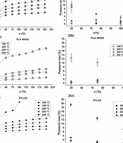
Paper II: The specific aim was to minimise the variation in thermomechanical properties of medical grade poly(L-lactide- co- -caprolactone) and poly(L-lactide-co-trimethylene carbonate) in an ARBURG plastic Freeformer. Selection of the process parameters was based on the viscoelastic behaviour of the polymers to minimise the variation within one batch cycle.
Paper III: The specific aim was to design a nondegradative additive manufacturing process and select processing parameters to fabricate scaffolds with medical grade lactide-co--caprolactone) and poly(L-lactide-co-trimethylene carbonate). The selection of processing parameters was based on the viscoelastic behaviour, filament stiffness, and thermal properties of the polymers.
Paper IV: The specific aim was to use the knowledge generated about printability in additive manufacturing of degradable polymers and apply it to poly(-caprolactone-co-dioxanone) to fabricate pliable scaffolds for soft tissue engineering.
Paper V: The specific aim was to achieve an understanding of how the structural design could influence the mechanical stiffness in the additive manufacturing and fabricate soft pliable scaffolds for soft tissue regeneration.
Introduction
4
2 Introduction
2.1 Tissue engineering
The term tissue engineering was coined in 1993 when Robert Langer and Joseph P. Vacanti reported how to replace or restore the function of an organ through the regeneration of new tissue.1 Three
different techniques were proposed for tissue regeneration: (i) cells could be injected on their own to repair the tissue; (ii) growth- factors could be added to aid the differentiation of the cells into the needed tissue;or (iii) the cells could be placed within a porous matrix. The porous matrix was described as a scaffold and could either be implanted on its own to be populated by cells in- vivo or cultured in- vitro before being inserted to replace the tissue. The scaffold was intended to provide the cells with a structure to manufacture their own extracellular matrix within, and it was assumed beneficial that the material should degrade within an appropriate time frame to allow for the newly created tissue to take its place.2, 3
Soft tissue engineering is a very broad term describing research with a focus regenerating connective tissue which has a supportive function of varying mechanical properties within the body but does not include mineralised tissue such as bone or blood. The common denominator is its viscoelastic behaviour due to the structural components of collagen and elastin, which vary depending on the load bearing capabilities.4-6 There is a need for soft tissue regeneration after both
trauma and surgery, one example is breast reconstruction.7 Autografts are
often taken of example adipose tissue, but this can lead to site morbidity and loss of volume due to resorption. Despite the low mechanical stiffness of the tissue, it has been found that retained structural support of the tissue is needed to rebuild the tissue.8, 9
One of the first methods to produce scaffolds for tissue engineering was through the leaching of porous agents such as salt or sugar.10 The
polymer was dissolved in an organic solvent such as chloroform and mixed with the porous agent. After the solvent had evaporated the salt particles were leached out in water. Porous structures were also manufactured by melting the polymer and passing pressured CO2 gas through.3 These
manufacturing methods created soft and highly porous structures for soft tissue engineering, but their architecture was not controlled. Developments within additive manufacturing (AM) have led to scaffolds of
Introduction
5
predetermined, more complex designs that can be manufactured with a wider array of polymers.11-16
2.2 Degradable polymers in medical applications
The aliphatic polyesters poly(L-lactide) (PLLA), poly(-caprolactone) (PCL) and polyglycolide (PGA) were first synthesised in the 1930s by Carothers through condensation polymerisation, which yielded polymers of low molar mass.17-20 Their brittleness, low strength and
hydrolytic degradation were deemed insufficient from an engineering perspective for any practical use. Through the development of ring-opening polymerisation, polymers of high molar mass and mechanical properties could be achieved with lactide and other lactones in the presence of initiators and catalysts such as ethylene glycol and Sn(Oct)2.17, 21-23 This synthesis route allowed for high reproducibility between batches
and increased molar mass with closer control of the stereo regularity. The thermal and mechanical properties of polylactide (PLA) depend on the feed ratio of the stereoisomers used in the polymerisation. Due to the chirality of lactic acid the stereoisomers L-Lactide, D-Lactide and DL-Lactide can be prepared.22 PLLA is a semicrystalline polymer with an elongation at
break of a few percent and a tensile modulus of approximately 2.7 GPa.22
The glass transition temperature (Tg) lies approximately 60 °C, the
polymer is therefore in the glassy state at body temperature. The inclusion of a few mol% of D-Lactide causes disorder in the crystalline lattice and thus reduces the degree of crystallinity (Xc) in comparison to the
homopolymer of L-Lactide. Polymerisation of a racemic mixture of D- and L-lactide yields an amorphous polymer with a Tg of 55 °C.22
Synthetic degradable polymers are commonly used within biomedical applications, monomers of lactide (LA), glycolide (GA), -caprolactone (CL), trimethylene carbonate (TMC) and p-dioxanone (PDX) are among the most utilised.18-20, 22 These monomers yield polymers that
are degradable through hydrolysis and have therefore been of interest for sutures and as implants. The physical properties and degradation rate are controlled by the repeating unit, composition, and block length.24, 25 LA has
often been copolymerised with CL and TMC to reduce the Tg and improve
the elongational properties.26-30
PLA and most aliphatic polyesters degrade primarily through bulk hydrolysis, meaning that the diffusion of water throughout the sample is faster than the hydrolysis of the ester bonds.31 The degradation rate
depends on multiple factors, mainly of repeating unit but also the molar mass, Xc, and the environment within which the polymer is placed.31, 32
Bulk degradation results in fragmentation of the device with a reduction in molar mass before mass loss is perceived, this reduces the time that the
Introduction
6
medical device can retain its properties. Random chain scission has been found to be the main degradation mechanism that controls the reduction in molar mass of polyesters of high molar mass, but end scission also occurs.33
In the 1960s the degradability of aliphatic polyesters gained interest within the field of medical devices to be used as a synthetic alternative to cat-gut, which could be resorbed within the body.20, 22 The
first available suture on the market was produced of PGA, a high Xc with a
Tg of approximately 40 °C and a comparable high mechanical stiffness of 7
GPa, which loses 50% of its tensile strength after two weeks.22 PDX was
also used for sutures, as the mechanical properties could be retained for longer than PGA; as a polyether- ester it has increased chain flexibility and hydrophilicity.34, 35 The Tg lies at approximately -20 °C, making it pliable at
body temperature. For the suture Maxon, GA was copolymerised with TMC to gain a longer resorption rate and fewer acidic degradation products.20 In
addition to polyesters, polytrimethylene carbonate (PLTMC) has been well used in nonload-bearing applications; it is amorphous and rubbery at room temperature.20 At a pH of 7.4 in vitro it has been found to be stable over
two years; however, degradation has been shown to be aided by enzymes, which make surface erosion an important factor.
During the late 20th century, interest rose in replacing permanent
metallic implants within orthopaedics with resorbable polymers.18, 19, 36, 37
One of the reasons was the difference in stiffness of the metallic implants compared to bone which resulted in stress shielding that could lead to osteoporosis and atrophy of the bone. Issues arose with the lack of thermal stability of the aliphatic polyesters, which resulted in a decrease in the molar mass during processing in addition to a reduction in molar mass during sterilisation.18, 36, 38 The mechanical properties additionally need to
be stable during the degradation time of the implant and regeneration of the bone.37
The low mechanical stiffness of PCL makes it more interesting for drug delivery applications than for sutures.20 The low Tg of -60 °C renders
it rubbery at body temperature and it has elastomeric behaviour with a long elongation at break.39 The hydrophobicity and high Xc result in a slow
degradation rate, where implantation in vivo have shown that no mass loss occurs during the first 6 months and that it can take up to 3 years for complete resorption.40, 41 After the polymer reaches 3 kg mol-1 phagocytosis
can aid degradation in addition to hydrolysis.42 The low melting point at
60 °C, high shear thinning ability and thermal stability make it a polymer which is easy to process and has been used to a great extend within scaffold fabrication through AM and tissue engineering.39
As a solution to the problem of the slow resorption rate of PCL the random copolymer poly(-caprolactone-co-p-dioxanone), (PCLDX), was designed within the Finne-Wistrand research group.43 Due to the inclusion
Introduction
7
of isolated units of dioxanone (DX), the copolymer has an increased hydrophilicity and degradation rate in comparison to PCL while maintaining a high thermal stability. This copolymer was used to fabricate pliable scaffolds through AM for soft tissue engineering applications in Paper IV.
2.2.1 Processing of polylactide (PLA) and the characteristic ratio It is well established that PLA has limited thermal stability, and a reduction in molar mass can occur despite careful drying of the polymer, therefore additives have been used stabilise the melt.23, 44 If there is any
water left the polymer undergoes thermal hydrolysis, and random oxidative chain scission will occur during isothermal heating at high temperature.23 PLA can additionally undergo zipperlike depolymerisation
and transesterification reactions, resulting in the formation of monomers of lactide and oligomers.45 Careful selection of temperatures and residence
time can limit the degradation of PLA and lactide- based copolymers, which is explored in Papers II and III. PLLA possesses a low elasticity and melt strength which makes it difficult to use in some traditional processing methods such as blow moulding which have been observed through rheological measurements and during processing.17, 46 The low melt
elasticity makes it very suitable for AM, such as fused filament fabrication (FFF).47 PCL, however, has a high elasticity in the melt and the rheological
behaviour is often described as favourable due to the thermal stability and high shear thinning behaviour.39, 48
The shorter repeating unit structure of PLA and additional carbonyl lowers the mobility of the polymer chain in comparison to that of PCL, rendering it stiffer. The low strength and elasticity in the melt of PLLA has been attributed to its low chain entanglement and high chain stiffness.17, 49 The chain stiffness of a polymer chain is reached at infinite
molar mass, referred to as the characteristic ratio (𝐶 ). The determination of 𝐶 together with the critical molar mass for entanglement (Mc), is often
done in solution, through viscometry and light scattering. A polymer chain can be described as a random coil where the size depends on the solvent in which it is in. If a polymer is in a good solvent, the size expands, and in a bad solvent, it shrinks. The molten state is said to be a theta solvent, thus estimated to be in between these two and where the polymer is not disturbed by its surroundings, often denoted by o.50 The end-to-end
distance (<r2>0) of a chain is affected by the number of bonds (n), the
length of each bond (l) and the characteristic ratio (C). The constant C depends on the repeating unit, molar mass, and temperature according to equation (2.2.1.1).50
Introduction
8
C reaches a limiting value for an infinite molar mass which describes the chain stiffness, C∞, equation (2.2.1.2). It can be calculated
from light scattering measurements if the number (x) of repeating units in a polymer chain and the length of each (𝑙 ) are known. A low value suggests that the chain can move freely, while a higher value estimates that the chain prefers some confirmations.49, 51
C∞ =lim
→ ∗ (2.2.1.2)
From light scattering experiments and measurements of the intrinsic viscosity Flory and Tonelli51 estimated the C∞ of PLLA to be 2,
thus, to behaving as freely rotating chains and having a high flexibility.50
As a comparison values for polyethylene have been reported to have a C∞
value of 6.7. There are contradictions between these experimental values, which largely depend on how the selection of number bonds has been made. Dorgan et al. estimated PLLA to have a C∞ value of 6.5 and thus a
stiffness similar to that of polyethylene.52 Joziasse et al. estimated C∞ with
light scattering studies and gained values of 9.5-11.8 depending on stereoregularity.49 The same group reported values of C∞ of PLLA to be
closer to 12 and copolymers of D and L-lactide to have a C∞ of 9.53 Their
estimation through viscosity measurements was based on the molar mass between entanglements (Me), Me = Mc/2, correlating it with 𝐶 according
to equation (2.2.1.3). The mass of the repeating unit (Mr) and (n) the
number of real or virtual bonds need to be known.53
Me = Mr (C∞)2 𝐶 𝑛 (2.2.1.3)
The critical molar mass for entanglement, Mc, has been estimated
for PLLA to be up to 16 kg mol-1, but values of 9 kg mol-1 have also been
reported.46, 53, 54 This can be compared to the value measured for PCL which
lies at 5,5 or 6 kg mol-1.55, 56 The values of Mc and C∞ are dependent on
experimental conditions such as temperature and choices in how to interpret for example the number of bonds. They can therefore not be applied directly to a processing situation or the melt rheology measurements performed in this thesis. It is however important to keep in mind the physical effect on the statistical mechanics of copolymerisation of lactide or when comparing the melt behaviour of polymers with different composition and molar masses. Rheological analysis has been used throughout Papers I-V to relate the melt behaviour to the process parameters.
Introduction
9
2.3 Melt rheology
The field of rheology can be described as a branch of nonlinear fluid mechanics that relates the flow behaviour of a viscoelastic material to an applied stress or deformation.57, 58 In polymer science it is used as a
translational tool to relate the chemical structure to its physical properties. Rheology has been extensively used in traditional processing to understand the effect of the repeating unit structure, molar mass, and dispersity on the physical behaviour.57, 58 Knowledge of the melt behaviour of the polymer
and how the change in shear and/or temperature affects the melt behaviour also aids the determination of parameters for AM.59-66
2.3.1 Small amplitude oscillatory shear rheology
The viscoelastic behaviour of a polymer melt is often determined under shear deformation using a parallel plate setup. An oscillating top plate imposes shear deformation onto the melt, and the response from the material is recorded. Small amplitude oscillatory shear rheology (SAOS) is the most often utilised approach. The measurements are conducted in the linear viscoelastic region, which means that the applied strain is so low that the shear relaxation modulus (𝐺) is independent of the strain. This results in the stress at any time being proportional to the strain.67 The shear rate
(𝛾) becomes a function of time according to equation (2.3.1.1), which is dependent on the frequency used (⍵) and the amplitude of the shear rate (𝛾 ⍵).
𝛾 𝑡 𝛾 ⍵ cos ⍵𝑡 (2.3.1.1)
The stress exerted by the sample after the periodic deformation also becomes a function of time if 𝛾 is small enough according to equation (2.3.1.2). It is controlled by the stress amplitude (𝜎 ) and phase angle (𝛿).67
𝜎 𝑡 𝜎 sin ⍵𝑡 𝛿 (2.3.1.2)
The amplitude ratio
𝐺 = (𝜎 /𝛾 )
is controlled by the frequency. When an oscillatory measurement is done, 𝜎 has two components, one in phase and one out of phase. The amplitude ratio of 𝜎 in-phase is referred to as the storage modulus (𝐺 ) according to equation (2.3.1.3). This is described as the elastic response and is the real component. The out-of-phase response is called the loss modulus, 𝐺 , which is dependent on the 𝛿 of the response and is therefore the imaginary viscous part according to the equation (2.3.1.4).67 The combined amplitude ratio of the real and imaginaryresponses is the magnitude of the complex modulus 𝐺∗ ⍵ according to
Introduction
10
𝐺 𝐺 cos 𝛿 (2.3.1.3) 𝐺 𝐺 sin 𝛿 (2.3.1.4) |𝐺∗| 𝐺 𝐺 (2.3.1.5)
The phase angle (𝛿) between 𝐺 and 𝐺 provides information on the relation between the viscous and elastic responses. If 𝐺 and 𝐺 are in phase, the response is entirely elastic, and if the phase angle is 90° it is entirely viscous. The ratio between the viscous to elastic response is referred to as Tan 𝛿 = 𝐺 /𝐺 .67 Tan 𝛿 or 𝛿 are both used to describe the
melt elasticity together with the complex viscosity (η∗). The magnitude of
η∗ is defined according to equation (2.3.1.6).67
|η∗| | ∗|
⍵ (2.3.1.6)
Cox-Merz empirically observed |η∗| (⍵) overlapping with the
viscosity of a steady shear rate η(𝛾) and that ⍵ =𝛾.67, 68 These
measurements were conducted with a plate-plate rheometer and a capillary rheometer using linear polystyrene samples with a number average molar weight (Mn) of approximately 80 kDa tested in the range of
0.1- 20 rad s-1. This relationship is often utilised in processing to relate the
oscillatory measurements to the steady shear.67 It has been found to hold
for aliphatic polyesters such as PCL and PLA.46, 48, 69 The rheological
behaviour of the polymer is related to 𝐶 and describes the melt behaviour under certain conditions. The rheological behaviour of the polymers was used throughout Papers I-V to set the process parameters in AM.
2.4 Additive manufacturing (AM)
AM is a general name for producing structures layer-by-layer rather than through a mould or removal of material.47, 70 It was first
invented in the 1980s as a rapid prototyping tool to physically visualise components. With technical developments over the past 40 years, it has become a highly diverse umbrella of technologies, utilising materials from gels to polymers, ceramics, and metals.47, 71, 72 Regardless of the AM
method, the produced geometry is first drawn in three dimensions in a software, referred to as the computer aided design (CAD) model. The CAD model is sliced into 2-D segments, where the thickness of each segment is referred to as the layer height. In melt-based AM the nozzle size and elasticity of the melt restrict the layer height. Often, the software is closed
Introduction
11
source and the printing path cannot be manually adjusted, which can cause issues in achieving the desired geometry.
AM has revolutionised the research within tissue engineering where intricate constructs can now be manufactured quickly with high reproducibility.11, 12, 72, 73 This provides a possibility to adapt the geometry
to the patient in question based on computer tomography (CT) data.74
Variation of the scaffold architecture can be made with close control of the pore size from the simple wood-stack features with strands at a 90° change in each layer used in Paper III to the use of finite element analysis (FEA) and computational fluid dynamics (CFD) to create hierarchical scaffold structures with predetermined mechanical and transport properties.12, 74-80
This provides an opportunity to tailor the properties given a certain polymer but by altering the pattern and design of the laid down strands in the scaffold. In Paper V, printed scaffolds were been designed for soft tissue engineering and mechanical properties were validated using FEA and CFD within the Finne-Wistrand research group. In this thesis, FFF and ARBURG Plastic Freeforming (APF) have been used; these are both hot- melt extrusion-based AM methods, but there are a range of other varieties.
2.4.1 Hot melt extrusion-based AM
The benefit of hot melt extrusion-based AM methods in medical devices is that there is no risk of additional residue of any crosslinking agent or solvents that could contain toxins for the cells.81 Medical devices
have also traditionally been manufactured through melt extrusion or injection moulding.12 The techniques are controlled purely through the
melting and deposition of a polymer, which after cooling below its crystallisation temperature (Tc) or Tg, solidifies on the build plate.47, 66
Issues related to melt processing of AM for tissue engineering are related to balancing the rheological behaviour to realise the complex geometric structures needed. The rheological behaviour of the melt controls the ability of the polymer to be extruded with the right diameter and to hold the shape on the build plate.66, 82 The viscoelastic behaviour of
the melt is often a limiting factor generally within melt processing or any AM technique.62, 82 There are, however, additional problems with aliphatic
polyesters of high molar mass due to the lack of thermal stability which causes a change in viscosity.83 The mechanical properties need to be
suitable to support the tissue during the regeneration time and a high porosity with interconnected pores is required for cells to penetrate within the structure. In scaffold fabrication the porosity and internal structure are of high importance, which means that the melt elasticity needs to be balanced with respect to temperature and speed to avoid die swell but still allows bridging gaps in the underlying layers.62, 66, 82, 84 Due to the small
nozzle size (0.25 – 0.4 mm) of the printers the viscoelastic behaviour needs to be precisely tailored. If the elasticity is too high in the melt die swell
Introduction
12
occurs at the nozzle end which results in dimensional errors, which can also arise in sharp turns.85 However, a complex geometry might require
that gaps between strands are bridged and for that elasticity of the melt is needed or a quick solidification time.66 This has been modelled using
computational fluid dynamics (CFD) in melts by others and has been extensively examined in all fields of AM.60, 61, 82, 86
2.4.2 Fused filament fabrication (FFF)
FFF is one of the most widely used AM manufacturing techniques due to its low cost and wide availability.47 A melt spun filament is fed
through a heated nozzle and deposited on the build-plate. The diameter of the filament is approximately 1.75 mm, while the nozzle head is 0.4 mm. The difference in size between the inlet and outlet results in the temperature needing to be raised significantly. The setup consists of the feeding of a melt-spun filament usually with a diameter of 1.75 mm into a heated nozzle with a much smaller diameter, approximately 0.4 mm. The two factors controlling the process are the temperature at the nozzle end and the feeding speed of the filament, thus the flow rate.84
The stiffness of the filament is an important aspect, brittle filaments can break during feeding, and flexible filaments can buckle.61, 63
The use of polymers with a low Tg and low molar mass can be elongated by
the feeding wheels instead of fed forward causing issues.61, 87, 88 Therefore,
the viscosity and elastic properties need to be balanced by the tensile properties of the filament. This error can be reduced through cooling of the feeding section, closer to the Tg and thereby increasing the rigidity of the
filament. The feeding speed can be reduced, and the design of the extruder is made in such a way that the feeding gears are near the nozzle head, to aid guide the filament down.63 Other issues often relate to inconsistency of
filament diameter, which causes a difference in mass flow or back flow within the nozzle head and back flow within the nozzle head.87 The
backflow at the nozzle end is related to the shear thinning ability of the polymers, and to obtain an estimation of this trait, the apparent wall shear rate can be estimated (γ) according to equation (2.4.2.1) if the feed rate of the filament (Q) and the radius of the nozzle (r) are known.87
γ
(2.4.2.1)
The FFF technique has been explored in Papers III-V to fabricate scaffolds. The selection of process parameters to optimise printability and a nondegradative processing method from the rheological behaviour, thermal and tensile properties has been the focus. Issues related to melt processing of AM for tissue engineering are related to balancing the rheological behaviour to realise the complex geometric structures needed.
Introduction
13
PLLA has been favourably used within the AM technology of FFF due to the high Tg and stiff nature of filaments, which allow for quick
feeding without buckling.63, 87 The low melt elasticity means it is easy to
print and that no die swell occurs. The melt is deposited onto the build plate and conforms to the intended design, with the high Tc also resulting
in quick solidification upon deposition.79 Due to the high Xc of PLLA which
has a Tg above body temperature the printed structures become brittle and
stiff. It is therefore more favourable within tissue engineering to use lactide based copolymers with a reduced Xc and lower Tg to gain a lower stiffness
of the printed structures at body temperature.20, 29
2.4.2.1 Melt spinning
To be able to use the FFF technique filaments need to be fabricated. Screw extruders are often used where the polymer granules are conveyed forward, molten and pressurised through a rotating screw and extruded through a die. The flow of the polymer melt in an extruder is complex. The process is driven through a combination of pressure and drag, controlled by the design of the extruder screw and barrel.57, 89
However, γ can be estimated according to equation (2.4.2.1.1) from the metering zone if the screw diameter (D) in mm, screw speed in rpm (N) and depth between the screw root and barrel wall (H) are known.57
γ 𝑠 (2.4.2.1.1) 2.4.3 ARBURG Plastic Freeforming (APF)
The APF technique is an AM method with a piezoelectric dispensing nozzle placed onto injection moulding technology.47, 90 The
advantage is the high pressure within the system and that standard plastic granules can be used directly in the hopper. The polymer is melted and conveyed forward using a screw, which is then retracted and used to push the melt into the nozzle cavity. The deposition volume is controlled through a piezoelectric piston that opens and closes access to the nozzle, which results in droplet-shaped depositions if the melt elasticity is sufficiently high enough. The main parameters controlling this process are the temperature set along the screw and the nozzle (Tn) as well as the discharge parameter (n(%)). n(%) corresponds to the screw displacement as a function of pressure.
The APF technique has broad industrial applications as a prototype tool due to the wide usage of injection moulding in industry and the benefit that granules or powders can be used directly.90 While medical
devices have been shown by the manufacturer as a potential usage, the scientific literature has mainly been concerned with differences in the mechanical properties to that of injection moulding in other products.91-93
Introduction
14
The adhesion and bonding between layers have been of particular interest, such as the dependency upon crystallinity in the interfacial bonding of PLA.94, 95 However, reduction in molar mass was found to occur. Because
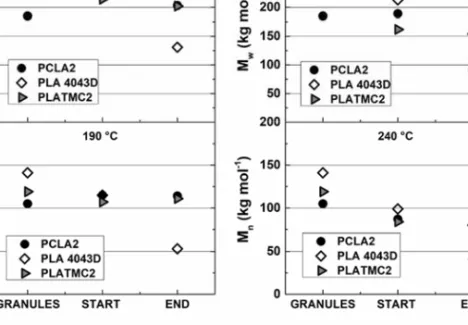
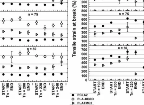
the process is conducted in batches, the properties of products made with thermally unstable polymers, such as LA based copolymers, are dependent on the processing conditions. The relationship between the processing conditions and thermomechanical properties was explored in Paper II to minimise the variation within one batch cycle.
2.4.4 Pneumatic-based extrusion
Pneumatic-based AM uses pressures of up to 7 or 9 bars to extrude ink from a syringe. This has successfully been employed to print bioinks and gels with or without the inclusion of cells.47, 70, 81, 96, 97 For melt-based
printing, polymer granules or flakes can be used directly. Heating is applied from the sides, and a low molar mass allows for easier printability due to the low pressure in the system.98 One example is the
3D-Bioplotter®, which has up to 9 bars. It has been found that when aliphatic polyesters of above 100 kg mol-1 is used in this system the molar mass is
halved before any extrusion can occur.83 The variation within one batch
cycle is often overlooked but must be considered in the case of aliphatic polyesters due to the long residence time.
2.4.5 Digital light processing (DLP)
One subgroup of AM utilises photopolymerisation to build each layer.15 In DLP, the pattern of each layer is projected onto a liquid resin.47
The liquid resin is placed in a bath with a projection from below, and the build plate moves upwards with each layer. The resolution is dependent on pixel size and screen resolution, but features down to 10 m and up to 1 m have been created.15 Resins are commonly acrylated monomers or
oligomers that are crosslinked through light, and copolymers of CL and TMC have been used to manufacture scaffolds.99 The equipment is
inexpensive compared to other techniques, but the resin needs to contain functional groups to allow for crosslinking and biocompatibility.
2.4.6 Selective laser sintering (SLS)
Another type of AM is SLS where a laser beam is used to sinter a powder of thermoplastic polymers.47 The powder is packed onto the
build-plate and the laser selectively sinters the path required for that layer by heating the polymer above its Tg. The particle size controls the resolution
to a large extent, but it is often practically limited to 100 m under optimal conditions. Agents to increase the spreading of powders are usually added, such as silica.100 The benefit of this technique is that the powder provides
Introduction
15
an internal support structure without the requirement of a sacrificial material or balancing of the viscoelastic properties to bridge gaps as is needed in extrusion-based systems.66, 101 However, nonmolten particles
can create an enhanced surface roughness.47 The equipment itself is rather
expensive compared to, for example, FFF due to the laser system. For scaffold fabrication SLS has for example been successfully employed with PCL.102, 103
2.4.7 Development of medical products with AM
Despite the large technical development of AM and tissue engineering, there are few available medical devices fabricated through these techniques on the market.12, 15, 73, 104 The available scaffolds are made
using thermally stable polymers with long degradation times.15, 77 One
reason for this is the cost related to regulatory approval; the cost to reach a stage where for approval for a class III device by the U.S Food and Drug Administration (FDA), a nonpreviously approved synthesised polymer in a degradable scaffold, can reach over $50 million.104
One of the main issues that the FDA states in their guidelines regarding the use of AM methods to produce medical devices is the control of the manufacturing processes and reproducibility between different machines.105 Calibration, operator dependency and the multitude of
parameters that can be tuned make this an issue. The wide variety of techniques, manufacturers and cross-disciplinarity within the field also makes it difficult to compare and discuss different results.64, 106 The issues
related to the fabrication of scaffolds with AM using aliphatic polyesters are the same as those faced with other processing techniques to control the degradation of the polymers during processing.38, 107 Depending on the AM
technique, there can be variation in the residence time of the melt within one batch cycle.83, 108 Thus, the properties of the products can vary within
one batch cycle.
2.5 United Nations sustainable development goals
This research was performed within a larger project called PrintKnit, whose overall goal was to develop pliable scaffolds for soft tissue engineering using AM methods. The project relates to United Nations sustainable development goal number 3, which concerns health and the development of well-being in humankind.109 The development and control
of AM could in the future allow for personalised scaffolds to be used within medicine to aid the body in repairing itself. This would increase the accessibility and decrease the cost of customised medical devices in line with target 3.8 to provide essential health care services. This could reduce
Introduction
16
the need for donor site morbidity for autologous grafts and reduce the dependency of donors. Soft tissue damage often occurs in traffic-related accidents, wound healing and regeneration of tissue therefore relate this work to target 3.6. Which concerns the treatment of injuries and reduction of the number of deaths in traffic accidents.
This thesis has contributed to United Nations Sustainable development goal number 8related to sustainable economic growth, with a specific focus on target 8.2.110 This target is related to higher levels of
economic productivity through technological upgrades and innovation. AM is a rapidly expanding field used within an increasing number of applications, especially FFF printing, which allows for quick customisation and production of simple devices at a low cost.47 By examining the
restrictions of AM, the assessment of the effect of the polymers and how to select parameters is how this thesis has aided further usage of this technique.
Materials and methods
17
3 Materials and methods
3.1 Polymers
3.1.1 Granules
Medical grade poly(L-lactide) RESOMER® L207S (PLLA), poly(D,L-lactide) RESOMER® R207S (PDLLA), poly(L-lactide-co-glycolide) RESOMER® LG824S (PLGA), poly(p-dioxanone) RESOMER® X206S (PDX), poly(L-lactide-co-ε-caprolactone) RESOMER® LC703S (PCLA) and poly(L-lactide-co-trimethylene carbonate) RESOMER® LT706S (PLATMC) were all purchased from Evonik (Essen, Germany) and used in Papers I–III. The polymers were stored in a closed nitrogen atmosphere in the refrigerator or in an Mbraun MB 150BG1 glovebox (Garching, Germany) before use. PDX was stored in a nitrogen atmosphere at - 20 °C.
Polylactide, Ingeo™ Biopolymer 4043D (PLA 4043D) used in Paper II and Ingeo™ Biopolymer 3251 D (PLA 3251D) used in Paper III were both purchased from NatureWorks (Minnesota, USA). Poly(ε-caprolactone) Capa 6800 (PCL Capa6800) was purchased from Kemi-Intressen AB (Solna, Sweden) and used in Paper III, and poly(ε-caprolactone) (PCL Sigma) with a number average molar mass of 80 kg mol−1 was purchased from Sigma-Aldrich (Darmstaat, Germany) and used
in Paper IV. Poly(-caprolactone-co-p-dioxanone) (PCLDX) with 15 mol% p-dioxanone was used in Paper IV, and it was stored at -20 °C in a nitrogen atmosphere before usage. The copolymer was synthesised within the research group, and the synthesis steps are stated in Paper IV and Fuoco et al.43
3.1.2 Purchased filaments
Poly(-caprolactone) filaments were purchased from 3D4 Makers (Haarlem, The Netherlands) and used in Paper III and V. Polylactide filaments were purchased from Creative Tools and used in Paper III (Halmstad, Sweden).
Materials and methods
18
3.2 Additive manufacturing (AM)
3.2.1 ARBURG Plastic Freeforming (APF)
The APF technique from ARBURG (Loßburg, Germany) was used in Paper II. The AM method is based on injection moulding technology, thus the screw melts and compresses the polymer before ejecting it into the nozzle head. This results in the extrusion of linked droplets. The droplet volume is controlled by the discharge parameter (n(%)) which adjusts the displacement of the screw and pressure exerted at the nozzle. The displacement of the screw was set to move from 17 mm to 3 mm, and this was considered one batch cycle. In the nozzle, a needle and piezoelectric actuator controls the deposition of the polymer. It opens and closes with a frequency of 145 Hz.
The temperature profile of the three heating zones in the screw was reported as a function of the nozzle temperature (Tn) from the feed to the die, 35 °C, Tn -20 °C, Tn -10 °C and Tn. The nozzle diameter was 250 µm, and ambient conditions were used in the build- chamber.
The screw was cleared of residual polymer after the heating step by purging two times before each new set of parameters was used. At least two strands were produced with each parameter setting, and the beginning and end of each strand were analysed. The pressure at the nozzle head (P) and time taken for each batch cycle were recorded after adjustments had been made to Tn and n(%).
3.2.2 Filament spinning
The manufactured filaments for AM were melt spun using a bench-top Felfil Filament extruder from Collettivo Cocomeri (Turino, Italy). The screw had a compression ratio of 1.47 and length/diameter ratio of 12.7. The extruder was fitted with a die of 1.75 mm and was run under ambient conditions. The speed of the gear motor ranged between 1-9 rpm. In Papers III and IV, a purpose-built winder was used, with a paper bobbin of 10 cm in diameter mounted to a gear shaft with an engine that had a rotational speed of 9 rpm, adjustable to two decimals.
3.2.3 Fused filament fabrication (FFF)
Scaffolds were fabricated using the FFF AM method with a fifth-generation Makerbot Replicator Desktop 3D printer from Stratasys (New York, United States). The filaments used were 1.75 mm in diameter, and the machine was fitted with a 0.4 mm nozzle. All computer-aided design (CAD) files were sliced and converted to .makerbot files using Makerbot Print software, which was also where the settings used for printing were made.
Materials and methods
19
In Paper III the CAD file of the linear woodstack structure was made within the Makerbot Print software, and the infill density was selected to be 25%. The strands were shifted in each layer at 90° to be perpendicular to each other. The scaffolds were designed to fit into a 48-well plate with a diameter of 10 mm and height of 4 mm.
In Papers IV and V, the CAD files were built in the assembly module of ABAQUS 6.14 from Dassault Systèmes (Vélizy-Villacoublay, France). After an STL file was exported, the files were first opened in Microsoft 3D builder (Washington, United States) and exported again as an STL file before use in Makerbot Print.
In Paper IV, a gradient structure designed within the group was printed. The strands in each layer were shifted 15° and were 0.4 mm in height. From the bottom to the top, the distance between the strands was set to 0.6, 0.6, 0.3, 0.6 and 0.6 for the five layers. Sheets were printed with dimensions of 75 x 75 x 2 mm. The scaffold porosity was theoretically 66%. In Paper V, five scaffold designs with dimensions of 10 mm in diameter and 3.6 mm in thickness were printed in basic (B), gradient (G), and gradient staggered (GS) designs. The distance between each printed strand was 0.4 mm. In the B designs, the orientation of the strands was shifted in each layer by 15 or 90°. In the G designs in addition to the shift in orientation of the strands as in B, the strand space was varied. The strand space was from the bottom layer to the top varied by 1.2, 1.2, 0.8, 0.8, 0.4, 0.8, 0.8, 1.2 and 1.2 mm. In the GS design the strand orientation was varied at 15° in each layer with the strand space varied from the bottom to the top as in the design. However, the strands were shortened and partially overlapped creating a staggered design. This avoids direct mechanical contact in the direction of the strand.
3.3 Characterisation methods
3.3.1 Thermal gravimetric analysis (TGA)
The mass loss through thermal decomposition was determined using TGA in a TGA/DSC 1 from Mettler Toledo (Columbus, United States) in a N2 or O2 atmosphere using 80 mL min-1, and a heating rate of 10 °C
min-1 in the temperature range of 25 - 500 °C with alumina cups as sample
holders. The temperature reported as the onset of mass loss was taken at 5% decrease in mass (T5%) and a sample size of approximately 10 mg was
used.
3.3.2 Differential scanning calorimetry (DSC)
The thermal behaviour of the polymers was determined through DSC, TGA/DSC 1 (Mettler Toledo, United States) calibrated with indium.
Materials and methods
20
A heating rate of 10 °C min-1, and 50 mL min-1 N2 was used in all runs, while
the temperature span was varied based on the region of interest. The first heating run was used to determine the effect of the thermal history of the polymer samples.
From the thermograms the melting peak temperature (Tm) was
determined, and the heat of fusion (ΔHm) was integrated. Where cold
crystallisation (Tc) was seen it was recorded, and the enthalpy of
crystallisation integrated (ΔHc). The glass transition temperature (Tg) was
taken as the midpoint ISO and was recorded where feasible in the first heating run; when it could not be seen in the first heating run, the second run was used to determine it. The degree of crystallinity in % (Xc) of the
samples was calculated according to equation (3.3.2.1) based on the measured endothermic and exothermic enthalpies and divided by the enthalpy of an infinitely large crystal of the polymer of interest (ΔHmo). The
ΔHmo for the PLA crystal was taken as 93 J g-1111 and the PDX 102.9 J g-1 112.
The enthalpies were normalised to the mass of the sample used and were therefore recorded as specific enthalpies.
𝑋
*100 (3.3.2.1)
In Paper I aluminium pans with a size of 100 µL were used, and a hole was punched. Samples of 7 - 9 mg were used. The first heating run had a temperature range from 25 to 220 °C. A cooling run was applied from 220 to -20°C. The second heating run spanned from -20 -220 °C.
In Paper II aluminium pans with a size of 40 µL and a hole was punched. Samples of 3-7 mg were used in a temperature span of 25 to 220 °C for all polymers.
In Paper III, aluminium pans with a size of 100 µL and a hole was punched. The samples of approximately 10 mg were used. A temperature span of 25-200 °C was used for PLA 3251D and purchased PLA filament. In the case of PCLA2 and PLATMC2 a temperature range of 25-220 °C were used. A cooling run was applied from 220 until -20°C. The temperature span for the second heating run was -20-220 °C. The temperature span in the first heating run was reduced for PCL Capa 6800 and the purchased PCL filament from 25 to 140 °C. The value used for the specific enthalpy of fusion for an infinitely large crystal was 142 J g-1,113 which was also used in
Paper V.
In Paper IV, aluminium pans with a size of 100 µL were used, a hole was punched, and samples of approximately 10 mg were used. The temperature span was 25 - 120 °C for PCL Sigma and PCLDX. The value used for the specific enthalpy of fusion in Paper IV was 136.1 J g-1.114
Materials and methods
21
polymers were performed from 120 to -30 °C at rates of 5, 10, 15 and 20 °C min-1.
3.3.3 Size exclusion chromatography (SEC)
The determination of the relative molar mass was performed through SEC. All measurements were conducted using CHCl3 as an eluent
and toluene as an internal flow mark. Low dispersity polystyrene standards were used for calibration. No corrections have been made for the difference in hydrodynamic volume between the polymers and calibrants, and the measured values have been used directly. The reported values are the number average molar mass (Mn), weight average molar mass (Mw) and
dispersity (Đ).
In Paper I, the measurements were made using a Verotech PL-GPC 50 Plus system fitted with two linear columns (PL-gel 5 μm Mixed- D) and a RI detector from Varian, Agilent (California, United States.). A PL-GPC 50 Plus autosampler was used, and the flow rate was 1 mL min-1 at 30
°C. Duplicates of all samples were done and the mean reported.
In Papers II-V, the measurements were made using a Viscotek GPCMAX system and autosampler from Malvern Panalytical (Malvern, United Kingdom) equipped with an RI detector and three columns. One guard column (PLgel 5 μm Guard) and two linear bead columns (PLgel 5 μm Mixed-D) with a flow rate of 0.5 mL min-1 at 35 °C were used. In Papers
III-V, triplicates were made of each sample.
3.3.4 Nuclear magnetic resonance spectroscopy (NMR)
The polymer composition and block length of the copolymer samples were characterised using NMR, 1H (400.13 MHz) and 13C (100.62
MHz) in CDCl3 at room temperature on a Bruker Avance 400 spectrometer
(Billerica, United States). The resonances and coupling constants are reported in ppm (δ) and Hz (J), respectively. The 1H NMR spectra were
referenced to the residual solvent proton peak at δ 7.26 ppm and the 13C
spectra to the 13C signal of CDCl3 at δ 77.16 ppm. The spectra were recorded
on Bruker TopSpin v2.1 software and analysed using MestReNova v.9.0.0 software. The peaks in the 1H and 13C spectra were assigned in accordance
with the literature.115-118
3.3.5 Rheology
A Fontijne TPB hot press (Delft, The Netherlands) was used to prepare samples for rheology. An aluminium mould made in-house was used; 20 mm in diameter and 2 mm in thickness. For each film 0.7 ± 0.05 g polymer was used. Compression moulding was conducted for 15 min encompassing heating and cooling of two cycles, at 20 and 100 kN at 4 °C
Materials and methods
22
above the measured Tm. The films were stored in a vacuum oven or
desiccator before analysis. This technique was used in Papers I, III and IV. The rheological analysis was performed with a DHR-2 from TA Instruments (New Castle, USA) fitted with 25 mm disposable smooth aluminium plates used within the environmental temperature chamber with N2 flow. A gap size of 1 mm was used for all tests with an applied
oscillation stress of 200 Pa. The compression moulded films were melted for 4 min and 30 s at the desired temperature before a trim gap of 100 µm was used, and the excess was removed with a metal spatula before the final gap was reached.
In Paper I, amplitude tests were first conducted at 1 Hz and Tm +4
for all polymers and then at Tm +54 and 50 Hz. The measurements were
made at two extreme points for the isothermal time sweeps were within the linear viscoelastic region of the polymers. Isothermal time sweeps were made for 15 min at 4, 24 and 54 °C above the measured Tm at frequencies
of 1, 10 and 50 Hz for each polymer. Triplicates of the test matrix were first made for PLLA to assess the repeatability of the system. Time sweeps were made to assess the thermal stability of the polymers at fixed frequencies within a feasible time frame for processing.
In Paper III, the effect of the temperature at a fixed frequency of 1 Hz was seen through temperature sweeps of the polymers. The sweep was performed through 5 °C steps, and a conditioning time of 30s was made at each point to allow the polymer melt to reach the temperature before a 10 s sampling time. The temperature spans used were 180-240 °C for PLLA, 160-240 °C for PCL Capa 6800 and 170 – 240 °C for PCLA and PLATMC. The temperature range was selected based on the region of interest seen for extrusion and FFF printing.
In Paper IV temperature ramps of PCL Sigma and PCLDX were made at a frequency of 1 Hz using a heating rate of 10 °C min -1. Based on
the Tm as measured in DSC and T5% from the TGA analysis, the temperature
ranges were selected to encompass a potential processing window. 70-250 °C for PCL Sigma and 55-250 °C for PCLDX. The number of points was maximised during the ramp with a 3 s conditioning time and 3 s sampling time.
3.3.6 Tensile testing
The mechanical properties of filaments, extruded strands and scaffolds were assessed using tensile testing. The experiments were conducted in a climate-controlled room with 50% humidity and 22 °C using an Instron 5944 (Norwood, United States) equipped with soft pneumatic rubber grips and a load cell of 500 N.
In Paper II, the strands used for analysis were left to equilibrate in the climate-controlled room for 24 h before analysis. The strands were cut into 100 mm specimens from the start and end of each batch and tested at
Materials and methods
23
a clamped length of 50 mm at a speed of 500% min-1 based on the initial
length.
Fourteen
repeats were made from each set of Tn and n(%). The samples were cut from two batches, where feasible the elastic modulus was calculated at 0.5-2.5% strain. For PLLA this range had to be decreased due to the high brittleness of the samples and strain rate. The strain at break was evaluated using Bluehill 3 software.In Paper III, the filaments were characterised using a clamped length of 50 mm and a rate of 25 mm min-1.At least three replicates were
made for each sample, with the average and standard deviations reported. The elastic modulus was calculated from the determined linear region.
In Paper IV, the tensile properties of the filaments and scaffolds were conditioned in a climate-controlled room for 24 h before analysis. For the filaments, 100 mm in length was used with a clamped length of 50 mm. The scaffolds were cut to a length of 30 mm in length and 4.5 mm in width. The thickness of the PCL Sigma scaffold was 1.4 mm, and the PCLDX scaffold was 1 mm. The average value of at least five replicates was reported with standard deviations.
3.3.7 Compression testing
The stiffness of the manufactured scaffolds was assessed using compression testing with an Instron 5566 instrument (Norwood, United States) in a climate-controlled room with 50% humidity and 22 °C.
In Paper III, a load cell of 500 N was used for PCL Capa 6800 and a 10 kN load cell was used for PLLA, PCLA2 and PLATMC2. The scaffolds were compressed until 60% deformation at a speed of 0.5 mm min-1, and
the stiffness was reported as an average and standard deviation of five samples. Each scaffold was printed separately and was approximately 9.5 mm in diameter and 4 mm in height to fit into a 48-cell well plate.
In Paper V, the scaffolds were equilibrated in a climate- controlled room for 24 h before testing. A 10 kN load cell was used for all designs. The rate of deformation was 0.35 mm min-1 corresponding to 10% of the
scaffold height, and the scaffolds were deformed up to 30%. Three measurements of the height and width for each sample and the average used. For each design, 7 replicates were performed, and the compressive modulus was determined between strains of 0.05-0.1 where the linear stress response vs strain was observed.
The theoretical height from the CAD file was 3.6 mm, depending on the scaffold design which ranged depending on the designs. The B designs showed an increased height of up to 4 mm, while the height was lower for the GS design down to 3.2 mm. The theoretical diameter of the CAD file was 9.5 mm in diameter. Depending on the design an increase of up to 10 mm in width was seen for the B design and a reduction down to 9 mm for the GS.
Materials and methods
24
3.3.8 Microcomputed Tomography (µ-CT)
The printed scaffolds in Papers III and V were analysed using µ-CT with the Skyscan 1172 system from Bruker Micro- µ-CT (Kontich, Belgium). A spatial resolution of 9 µm was used with an operation voltage set to 40 kV and a utilised current of 250 µA, and no filter was employed. Three replicates of each characterised design were used. The porosity mean pore size and surface area to volume ratio were analysed with CTAn (CT analyser, ver. 1.18, SkyScan). The three-dimensional images of the scaffolds were generated using CTVox (CTVox version 2.7, SkyScan) software.
3.3.9 Tabletop scanning electron microscope (SEM)
In Paper II-V the morphologies of the scaffolds and filaments were characterised using a TM-1000 tabletop SEM from Hitachi (Tokyo, Japan). The acceleration voltage was 15 kV and no conductive coatings were used on the samples. Samples were sectioned after immersion in liquid nitrogen for the cross-sectional micrographs in Papers III and V.
Results and discussion
25
4 Results and discussion
One way to overcome the problems of printability is to use polymers of a lower molar mass, but to fabricate scaffolds with retained mechanical properties over time a high molar mass is needed. To adjust the processing route and parameters to the degradable polymers, polymers of medical grade or synthesised in-house with an Mn near 100 kg mol-1 were
chosen for use in this thesis.
The structure property relationships of lactide copolymers with varying compositions were set based on rheological measurements to ease their usage in melt-based AM with the aim of limiting thermal degradation. The rheological measurements were aided with mechanical and thermal characterisation methods to find a suitable processing window. The polymers were used as received or synthesised in this thesis. They were characterised before use based on composition, microstructure, and inherent viscosity (IV) in Table 4.1. PCLA and PLATMC are labelled in Tables 4.1 and 4.2 with respect to the batch used, (1) for the first and (2) for the second. The granules and purchased filaments were also characterised with respect to the molar mass and thermal properties, as shown in Table 4.2.
Results and discussion
26
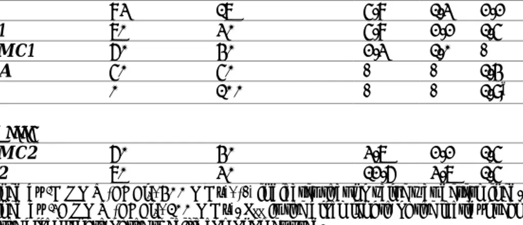
Table 4.1. Composition, microstructure, and inherent viscosity of the as- received medical
grade granules.
Polymer L-Lactide
(mol%)a Co- monomer (mol%)a LLLb Lxb IV (dL g-1)c
Paper I PLLA 100 0 - - 1.9 PLGA 83 17 5.8 1.3 2.2 PCLA1 70 30 5.8 2.2 1.5 PLATMC1 60 40 2.3 1.0 - PDLLA 50 50 - - 1.4 PDX 0 100 - - 1.9d Paper II and III: PLATMC2 60 40 3.7 2.2 1.5 PCLA2 70 30 12.6 3.7 1.5
aDetermined by 1H NMR (CDCl3, 400 MHz), (-) indicates that no value was determined. bDetermined by 13C NMR (CDCl3, 100 MHz). LLL is the block length of the lactidyl segment, and Lx is the block length of the specific comonomer used.
cInherent viscosity (25 °C, 0.1%, CHCl3) as reported by Evonik. dInherent viscosity (25 °C, 0.1%, HFIP) as reported by Evonik.