doi: 10.17265/1934-7359/2018.02.001
Repairing of RC T-Section Beams with Opening by
CFRP for Cracks and Ultimate Torque
Ali Sabah Al Amli1, Nadhir Al-Ansari2 and Sabah Jasim Dahboosh Shejiri3
1. Civil Engineering Department, AlMustansiriyah Engineering College, ALMustansiriyah University, Baghdad 1001, Iraq 2. Department of Civil, Environmental and Natural Resources Engineering, Lulea Technology University, Lulea 971 87, Sweden 3. Department of Civil Engineering, AL-Farabi University College, Baghdad 1001, Iraq
Abstract: The repair of reinforced concrete (RC) beams with carbon fiber reinforced polymers (CFRP) is experimentally
investigated in this study. The four T-section reinforced reactive powder concrete beams with many locations of circular opening were repaired by CFRP and investigated under pure torsion. The repairing beams were tested to obtain the effect of the amount of CFRP laminate on beams cracking and ultimate torque behavior, angle of twist and failure modes. The results obtained from the adopted repairing technique showed a significant effect of external high strength CFRP laminates on effectively restore of section solid of 85% of crack torsional strength effectively restored. In addition, the results show that effectively restoring of section opening by 82%-80% of crack torsional strength, and the adopted repairing technique gives a good strength to the beams.
Key words: Torque, first and ultimate cracks, RPC, opening, T-section, repairing, carbon fiber reinforced polymer (CFRP).
1. Introduction
Carbon fiber-reinforced polymers (CFRP) are currently used worldwide to retrofit and repair structurally deficient infrastructures such as bridges and buildings. Using CFRP reinforcing bars in new concrete can eliminate potential corrosion problems and substantially increase member’s structural strength. When reinforced concrete (RC) members are strengthened with externally bonded CFRP, the bond between the CFRP and RC substrate significantly affects the member’s load-carrying capacity. This article presents the effects of adverse environmental conditions on the deflections and ultimate load-carrying capacities of beams strengthened with externally bonded CFRP [1, 2]. Long-term exposure to humidity was the most detrimental to the bond between the CFRP and the RC. Delamination was the primary failure mode for the tested beams. The CFRP strengthening provides additional flexural or shear
Corresponding author: Nadhir A. Al-Ansari, professor,
research fields: water resources and environment.
reinforcement; the reliability for this material application depends on how well they are bonded and can transfer stress from the concrete component to CFRP laminate [3]. Although CFRP composites are known to perform better under environmental action than glass fiber reinforced polymer laminates. No significant differences were detected, seemingly because using of carbon fiber reinforced polymer laminated for strengthening reinforced concrete beams in failure was not due to rupture of the fibers [4].
While concrete is one of the most widely used construction materials in the world, the durability of concrete is critical as it would have great effect on the service life of civil infrastructure and building. However, they are vulnerable to corrosion when concrete structures are exposed to severe environmental conditions. Corrosion causes section loss in the reinforcing steel; therefore, it affects the load carrying capacity of the concrete structure. Corrosion resembles a major threat to hinder the durability and safety of concrete structures. CFRP is used in strengthening and restoration of concrete
D
structures, thus it can be used to restore the capacity of concrete structures with the corrosion problem. CFRP composites are commonly used when there are deficiencies in the quality of concrete and lack of adequate confinement reinforcement [5, 6].
The tests showed that it is benefical to use the CFRP sheet to cracks so that they are useful to use for many types of concrete failing [7-9]. Beams, columns and any other types or sections for reinforced concrte structures of differen types of cracks use the CFRP for repairing purposes.
2. Experimental Pogram
Experimental program consists of testing of four specimens damaged. The specimens were casted and tested by Refs. [10, 11]. In this work, these specimens were repaired using CFRP, then they were tested under pure torsion. The dimensions of T-beam are as follows:
bw (width) = 100 mm h (total thickness) = 280 mm bf (bottom and top width) = 320 mm
tf (thickness of flange) = 80 mm length = 1,300 mm
The reinforcements for beams were with stirrups as distributed with bottom reinforcement 2Φ10, top
reinforcement 2Φ6, shear reinforcement Φ6@200 mm. The total tested beams were 10 having the same geometry and steel reinforcement.
The main variables adopted in the experimental work were web opening: the opening in this study contains variables in location and number.
3. Opening Layout
The openings layout and configurations in the web of the T-section beams, are shown in Table 1. Three beams with many locations of opening and one beam without opening are shown in this table.
3.1 FRP Material Properties
The Sika Wrap Hex-230C is an externally applied strengthening or repairing the system for structural members made of reinforced concrete [12]. This system was supplied by Sika near East s. a, I. Beirut—Lebanon. Epoxy based impregnating resin Sikadur—330 were used with fabric [12]. The following information related to this system is listed in Tables 2 and 3.
3.2 Effects of Repairing by CFRP
Beam Number 1 represents solid web without opening (control beam), the maximum first cracks torque
Table 1 Details of beams and web openings.
Specimen mark Details of opening
T rep 1 B1 No opening
T rep 2 B2 Circle Φ 100mm @ center of beam span
T rep 3 B3 Circle Φ 100mm @ 1/3 of beam span
T rep 4 B4 Circle Φ 100mm @ center of beam span and Φ 100mm @ 1/3 of beam span
Table 2 Sika Wrap Hex-230C (carbon fiber fabric).
Fiber type High strength carbon fibers
Fiber orientation 0◦ (unidirectional). The fabric is equipped with special weft fibers which
prevent loosening of the roving (heatset process)
Areal weight 225 g/m2
Fabric design thickness 0.13 mm (based on total area of carbon fibers)
Tensile strength of fibers 3500 MPa
Tensile E—modulus of fibers 230 GPa Elongation at break 1.5 % Fabric length/roll ≥ 45.7 m Fabric width 305/610 mm
Table 3 Sikadur-330 (impregnating resin). Appearance Comp. a: white Comp. b: grey Density 1.31 kg/L (mixed) Mixing ratio A : B = 4 : 1 by weight Open time 30 min (at + 35 °C) Viscosity Pasty, not flowable
Application temperature + 15° C to + 35 °C (ambient and substrate)
Tensile strength 30 MPa (cured 7 days at +23 °C)
Flexural E-modulus 3800 MPa (cured 7 days at +23 °C)
is 27.5 kN·m, but B1 before repairing needed (32.5 kN·m) for the first crack. That means the beam restored 85% of torque capacity in the solid beam, but the beam with opening like B2 where the maximum first cracks torque is 20 kN·m, but B2 before repairing need 25 kN·m for first crack. That means beam with opening reducing the crack torque and angle of twist.
3.3 Cracked Stage
The results of cracking stage before repairing taken from Ref. [10] (Figss. 1 and 2) show the comparisons between all tested beams specimen up to the first crack. In general for all tested beams that were compared with repairing beams, the interesting points for discussion are the torque for first crack for B2-4 was less than B1, angle of twist at first crack was less; the linearity behavior of control beam was more. All tested beams that were directed to the horizontal axis indicated that the RC T-beams become weaker when the applied torque increased in loading.
The relationship between angles of twists and distance was compared for all tested beams. The control beam behaved as linear and the angle of twist increased as the distance increased because of increasing in applied torque. The main point in case of presence web opening in RC T-section is that when all tested beams were compared with that control B1, the behavior of all beams that appear from the curves below concluded with T-section behaved as solid web. It should be mentioned, however, that the effects of opening refer to the reducing of the values of cracking and ultimate torque and corresponding twisted angles. The repairing beams (rep 1 to rep 4), while the
original beams before repairing are (Beam No. 1 to Beam No. 4), respectively (Figs. 1 and 2).
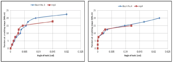
3.4 Ultimate Stage
Figs. 3 and 4 show the comparisons between all tested beams specimen up to ultimate loading capacity (failure). In general, for all tested beams, t indicated that there was a reduction in cracked failure ultimate torque with corresponding angle of twist. All behaviors of tested beams from Figs. 3 and 4 are lying and oriented parallel to the x-axis that indicated after the inflection point that translate the beams behavior from linear and formulating plastic hinge so that the beam became weak due to increasing in applied loading.
Angles of twists and distance were compared for all specimens. The control beam behaved as linear and the angle of twist increased because the twisted angle is a function of applied torque. The cracked twisted angle for B1 was greater than other beams because of the presence of web perforation that caused a reduction in torque strength capacity. The experimental results to cracking torque are listed in Table 4. The repaired beams are rep1 to rep 4, while the original beams before repairing are Beam No. 1 to Beam No. 4, respectively.
3.5 Cracks Development
Fig. 5 shows the propagation of the cracks for all tested RC T-beams. The locations of their opening are shown in Table 1. All cracks started from the bottom of the web with spiral form toward the flange. The shape of cracks is similar. They are rounded and
Beam No. B1 Beam No. B2
Beam No. B3 Beam No. B4
Fig. 1 Comparison Angle of twist vs. distance relationship for beams.
Beam No. B3 Beam No. B4
Fig. 2 Comparison Cracks torque vs. angle of twist relationship for beams.
Beam No. B1 Beam No. B2
Beam No. B3 Beam No. B4
Beam No. B1 Beam No. B2
Beam No. B3 Beam No. B4
Fig. 4 Comparison Torsion vs. angle of twist for beams in ultimate stage. Table 4 Experimental results for cracking torque.
% twist angle after repairing/twist angle before repairing % torque after repairing/torque before repairing Maximum
angle of twist (rad.) after repairing Maximum
torque (kN·m) after repairing Maximum
angle of twist (rad.) before repairing Maximum torque (kN·m) before repairing Beam mark 83 85 0.01469 36.125 0.0177 42.5 B1 80.5 82 0.01997 30.75 0.02481 37.5 B2 79 81.5 0.02069 23.7 0.02619 30.0 B3 78.5 80 0.03077 21.58 0.0392 27.5 B4
rep1 rep2
rep3 rep4
Fig. 5 The locations of openings for tested repairing beams.
connected together to form spiral cracks in the direction of opposite applied torque. The cracks intensity was around the web perforation because the weak region is around the opening.
4. Concluions
According to the results from experimental tests, the following conclusions were drawn:
(1) The repairing restores 80% to 85% torsional strength. This indicates that the adopted technique gives good torsional strength.
(2) The provision of the opening in the beams leads to decrease in the cracking and ultimate torsional strength of the beam, when using the same longitudinal and transverse reinforcements.
(3) The cracks start from the support and then take a spiral shape around the beams up to flange so the amount of cracks increased according to the presence
of openings.
(4) There is a small rise in the angle of twist in the repaired beams compared to the original beams.
References
[1] Ozcebe, G., Ersoy, U., Tunkat, T., Akyuz, U., and Erduran, E. 2004. “Rehabilitation of Exist Reinforced Concrete Structures Using CFRP Fabrics.” Presented at 13th World Conference on Earthquake Engineering, Vancouver, B.C., Canada. No.1393.
[2] Banthia, N. 2014. “Fiber Reinforced Polymer in Concrete Construction and Advanced Repair Technology.” Vancour, B.C., Canada, V6T 1Z4.
[3] Ekenel, M., Stephen, V., Myers, J. J., and Zoughi, R. 2004. “Microwave NDE of RC Beams Strengthened with CFRP Laminates Containing Surface Defects and Tested Under Cyclic Loading.” Electrical and Computer Engineering, University of Missouri-Rolla, Rolla, MO 65409, USA, 1-8.
[4] Silva, M. A. G., and Biscaia, H. 2008. “Degradation of Bond between FRP and RC Beams.” Composite Structures 85: 164-74.
[5] Alper, I., and Nahit, K. 2002. “Repair and Strengthening of Damaged Reinforced Concrete Members by Carbon Fiber Reinforced Polymer Composites.” Teknik Dergi Tech. J. Turk. Chamb. Civ. Eng. 13: 2597-616.
[6] Adhikary, B. B., and Mutsuyoshi, H. 2004. “Behavior of Concrete Beams Strengthened in Shear with Carbon-Fiber Sheets.” Journal of Composites for Construction 8 (3): 258-64.
[7] Olivova, K., and Bilcik, J. 2008. “Strengthening of Concrete Columns with CFRP.” Slovak Journal of Civil Engineering 2009/1: 1-9.
[8] Bukhari, A. I., Vollum, L. R., Ahmad, S., and Sagaseta, J. 2010. “Shear Strengthening of Reinforced Concrete Beams with CFRP.” Magazine of Concrete Research 62 (1): 65-77.
[9] Lee, C., and Bonacci, J. F., Tomas, M. D. A., Maalej, M.,
Khajehpour, S., Hearn, N., Pantazopoulou, S., and Sheikh, S. 2000. “Accelerant Corrosion and Repair of Reinforced Concrete Columns Using Carbon Fiber Reinforced Polymer Sheets.” Can. J. Civil Eng. 27: 941-8.
[10] Al Amli, A. S., Mehdi, H. A., and Ahmed, R. H. 2016. “Cracks Torque of T Section R.C Beam with Web Perforation Using Reactive Powder Concrete.” IJCSEIERD, 6, 3, edition, June, 2016.
[11] Ahmed, R. H. 2016. “Behavior of Reactive Powder R.C. T-Section Beams with Openings for Pure Torsion.” M.Sc. thesis, University of Al-Mustansiriyah, Baghdad, Iraq, 2016.
[12] Ahmed, A. S. 2017. “Behavior of Repaired Composite Modified Reactive Powder Concrete I Section Beams with Opening under Pure Torque.” J. of Engineering and Sustainable Development 21 (1): 39-50.