School of Innovation Design and Engineering
V¨
aster˚
as, Sweden
Thesis for the Degree of Master of Science in Intelligent
Embedded Systems
ENABLING DATA SHARING
WITH DDS ON REAL-TIME
CONSTRAINED INDUSTRIAL
ROBOTS
Sergio Erick Vieyra Enr´ıquez
svz13001@student.mdh.se
Examiner: Moris Behnam
M¨
alardalen University, V¨
aster˚
as, Sweden
Supervisor: Saad Mubeen
M¨
alardalen University, V¨
aster˚
as, Sweden
Company supervisor: Kristian Sandstr¨
om,
ABB Corporate Research,
V¨
aster˚
as , Sweden
Abstract
Data Distribution Service (DDS) is a decentralized, zero-configuration, communica-tion middle-ware. This thesis presents a performance analysis of a communicacommunica-tion based on DDS in the context of industrial robotics. The purpose is to find out if DDS is an adequate alternative for establishing a communication network between indus-trial robots, as well as other devices, and consider the advantages and disadvantages that this technology brings. Several current works are explored to give an insight in the current state of smart industrial automation, as well as to serve as a basis for the tests conducted in this thesis related to DDS performance. Using ABB industrial robots, a prototype is prepared and a series of experiments are carried out in order to measure the performance of the connection compared to a traditional end-to-end Transmission Control Protocol (TCP) socket. After explaining both the software and hardware architecture of the build setup, several test cases are presented in order to compare the performance of the system with different configuration pa-rameters and network traffic conditions. An analytic review on the capabilities of the prototype, based on the test data is presented. The specific DDS distribution used in this thesis complies with the requirements needed by ABB robots in many different applications.
Acknowledgements
I want to thank my university supervisor at M¨alardalen University, Saad Mubeen, and my thesis evaluator, Moris Behnam, who kindly provided very valuable feedback and expertise to help me improve this thesis. I am also very thankful for the support and technical expertise that I received from Kristian Sandstr¨om, Larisa Rizvanovic and Hongyu Pei-Breivold in ABB Corporate Research. I am very grateful for the opportunity to work in this project which brought me a chance to develop myself academically and professionally.
Table of Contents
1 Introduction 5 1.1 Motivation . . . 5 1.2 Problem Definition . . . 6 1.2.1 System Overview . . . 6 1.3 Thesis Outline . . . 6 2 Background 9 2.1 Industrial Robot . . . 9 2.1.1 Robot Arm . . . 9 2.1.2 Robot Controller . . . 102.2 Data Distribution Service . . . 10
2.2.1 Overview . . . 10
2.2.2 Structure . . . 11
2.2.3 Quality of Service . . . 12
2.2.4 Real-Time Publish Subscribe Protocol . . . 12
2.3 Real-Time System . . . 13 2.3.1 Definition . . . 13 2.3.2 Characteristics . . . 13 2.4 Other terms . . . 14 2.4.1 Overview . . . 14 2.4.2 Internet of Things . . . 14 2.4.3 Industrial IoT . . . 15 2.4.4 Cloud Computing . . . 15 3 Related work 17 3.1 The Real-Time Publish/Subscribe Protocol . . . 17
3.1.1 RTPS use in Distributed Systems . . . 17
3.1.2 DDS Performance . . . 17
3.2 Industrial Robotics . . . 18
3.2.1 Robot Collaboration . . . 18
3.2.2 Industrial Data . . . 18
3.3 State of the Art . . . 19
4 Research methodology 20 4.1 Overview . . . 20 4.2 Conceptual Framework . . . 20 4.2.1 Research Objectives . . . 20 4.2.2 Expected Outcomes . . . 21 4.3 System Architecture . . . 21
4.4 Analysis and Design . . . 21
4.4.1 Initial Design . . . 21
4.4.2 Time Constraints . . . 22
4.5 Development . . . 22
4.5.1 Development Stages . . . 22
5 System architecture 23
5.1 Overview . . . 23
5.2 The Robot Controller . . . 23
5.2.1 The Teach-Pendant . . . 24
5.2.2 The Controller’s Firmware . . . 24
5.3 The Central PC . . . 24
6 Implementation 25 6.1 The Base Experimental Setup . . . 25
6.2 The DDS Experimental Setup . . . 26
6.3 The Communication Algorithm . . . 26
6.3.1 Robot R1’s Algorithm . . . 26
6.3.2 Implementing the C++ Module . . . 26
6.3.3 Robot R2’s Algorithm . . . 28
7 Experimental Results and Evaluation 31 7.1 Testing Methodology . . . 31
7.1.1 The Conducted Experiment . . . 31
7.1.2 Data to be Logged . . . 33
7.2 Socket Measurements . . . 34
7.2.1 Basic Setup Measurements . . . 34
7.2.2 Observations . . . 35
7.3 Complete Setup Measurements . . . 36
7.3.1 Observations . . . 39
7.4 Communication Layer Measurements . . . 40
7.4.1 Observations . . . 41
7.5 DDS-specific Measurements . . . 42
7.5.1 The DDS Performance Test . . . 44
7.5.2 The DDS Subscribers Test . . . 46
7.5.3 Observations . . . 48
7.6 Analysis and Discussion . . . 49
7.6.1 Advantages: Flexibility and Scalability . . . 49
7.6.2 Disadvantages: Latency and Timeliness . . . 49
7.6.3 Reliability in the QoS . . . 51
8 Conclusions 52 8.1 Summary . . . 52
8.2 Future Work . . . 52
8.2.1 RAPID/DDS Coupling . . . 52
8.2.2 Possible Future DDS Use-cases . . . 52
1
Introduction
1.1
Motivation
The tasks that a robot can perform have greatly been constrained, among other reasons, by the processing power that the robot itself has. Some of these criti-cal tasks, such as criti-calculating and planing a path, recognizing a pattern or finding an optimal solution to a new problem, require a very large amount of processing time, therefore, a cost-efficient way of providing this processing power is needed. Despite the decreasing and improving performances of computer systems many of these problems still require very powerful processing units in comparison to the embedded solutions often used in robotics [1, 2, 3]. Even more, in the context of machine learning and artificial intelligence, large amounts of data are required in order to run an algorithm. Communication and data sharing among other machines or with the users is another need that most robotic systems have, which adds up to the final complexity of the system. Industrial robots are usually more constrained than their mobile counterparts since the applications that industrial robots perform have more demanding safety requirements. The safety constraints, reliability, and prolonged up-times that industrial robots require are achieved by slow (but highly deterministic) processors. Nonetheless, industrial robots have been able to fulfill their duties with the aforementioned constraints since their usual tasks are not too demanding on processing power. In other words, industrial robots are usually more concerned with metrics like repeatability, speed, and up-time rather than decision making or pattern recognition.
The advent of the Smart Factory poses a big challenge in many industrial areas: the manufacturing process, which historically has been a rigid, expensive and “custom-made” solution, is seeking to modernize itself and reduce costs, energy consump-tion and deployment complexity while increasing its robustness and flexibility [4]. Consequently, industrial robots face new challenges. The topic of flexibility and highly-customized manufacturing has taken great relevance in the last few years [5]. A flexible manufacturing process is one that can react to both deliberate and undeliberate changes in the manufacturing line. Interconnecting several stages of the manufacturing process could lead to a greater flexibility and an autonomous response to changes. Even more, these changes could be requested by a customer asking for a special requirement in its product [4, 6]. The Smart Factory will be defined by these kind of future scenarios during the upcoming years.
By connecting an industrial robot to a network in the manufacturing plant, a plethora of possibilities arises. Sharing the information within the robot and other machines from different stages of the manufacturing process can lead to complex synchronized behaviors and more flexible lines of production [6].
This thesis explores the possibility of connecting a series of industrial robots to a local cloud in order to exchange information with each other, as well as with other machines and operators. A cloud architecture is deployed where the robots can freely communicate with other machines using a networking middle-ware and they can request services from both a local and a remote cloud in order to gain new capabilities or extend their existing ones. For this work, the Data Distribution Ser-vice, or DDS for short, has been selected by ABB to serve as the communication
middle-ware that implements the communication over a local cloud. The reasons for the selection of DDS include its robustness in real-time systems, de-centralized design and its no-configuration peer-discovery [7].
1.2
Problem Definition
For a given network topology implemented locally over Ethernet and based on DDS running on an industrial robot controller, we explore the following question:
What is the performance impact that this new DDS-based communication will have in comparison to an end-to-end TCP socket
communication?
In order to answer this question in an industrial context, we will develop a proto-type setup using two ABB industrial robots and its corresponding industrial robot controllers. Because of the software architecture of the controller, a robot appli-cation only has access to a predefined set of communiappli-cation mechanisms, therefore a software workaround needs to be created in order to avoid this constrain, which further impacts the performance of the system. In concrete terms, this thesis inves-tigates a proposed software architecture and network setup in order to understand its real-time performance and whether or not DDS is an adequate technology for ABB industrial robots.
1.2.1 System Overview
A networked setup is tested during this thesis in order to understand the advantages and limitations of a DDS-based robot communication. Figure 1 shows a very basic setup where the relevant components are present. A description of the system’s parts is also provided.
1. The industrial robots
These robots are the main agents on the implemented communication scheme. They exchange data among them and with the cloud.
2. The central computer
A computer that closely monitors the state of the system (up-time, iterations, joint positions, etc) and provides access to the local and remote clouds as requested by the robots or other devices.
3. Other devices
This devices can range from personal computers to tablets and cellphones. The purpose these devices is to monitor and access information regarding the current state of the system.
1.3
Thesis Outline
Figure 1: A basic diagram of the network topology that will be employed during this work.
Introduction: An introductory section, stating the goals, challenges and motiva-tion of the thesis is presented at the beginning of this work. The motivamotiva-tion and relevance of the work’s topic is highlighted and the problem is briefly defined.
Background: A general overview and explanation of the involved technologies populate this section. The Background contains information meant to familiarize the reader with the concepts and terminology that this work uses. A quick theoretical overview into the concepts of industrial robotics, DDS communication, and real-time systems is presented here.
Related Work: this section showcases some of the research already conducted on the field that serves as the basis for this thesis.
Research Methodology: a systematical approach regarding the performed re-search for this thesis is presented in this section. An explanation on the methodology itself, as well as the tasks regarding the thesis itself are presented for the reader.
System Architecture: this section presents in a detailed way the entities that constitute the system to implement. The hardware, network topology, software, as well as the task that the robots need to carry out, are presented during this section.
Implementation: in this phase the process to develop and deploy the system is presented. The tasks for developing the system’s architecture, the software and the integration of the DDS facilities are discussed here.
Experimental Results and Evaluation: this part of the thesis explains the tests used to evaluate the system, the results obtained and the learned outcomes. A discussion feature, containing the advantages and disadvantages of the aforemen-tioned system is also presented.
Conclusions: in the last part of the thesis, a summary of the thesis is presented along with a suggestion for the future work that should be performed with this project and future scenarios that could benefit from a similar communication setup.
2
Background
The basic concepts that the reader must be aware of are presented in this section. Both robotics, embedded and cloud systems are areas that span over a vast amount of topics and research areas. The following sections provide a brief introduction to these topics and the relevance they have for the thesis.
2.1
Industrial Robot
We can define an industrial robot as an “automatically controlled, re-programmable, multipurpose manipulator, programmable in three or more axes, which can be either fixed in place or mobile for use in industrial automation applications” [8].
An industrial robot is a manipulator widely used in the automation industry in order to perform a predefined task. This type of robot is designed to perform repetitive tasks that are unsuitable for a human worker. Given the nature of its purpose, industrial robots must compel with strict safety constraints. Since the field of industrial robotics is very vast, this thesis focuses on the kinematic chain type of industrial robots, commonly known as industrial robot arms.
2.1.1 Robot Arm
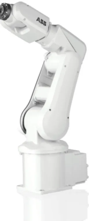
A robot arm consists of a series of articulated links connected by powerful actuators in its joints. This is a very common type of robot in the automation industry since it provides a great amount of flexibility that can be employed in a plethora of tasks. The end part of a robotic arm, or the tool that the robot “is holding” is refereed to as the end effector. In order to program an industrial robot, instructions that command the robot to move to a certain point in space with a certain orientation of its end effector are needed. Figure 2 shows a typical industrial robot arm. The robot program must translate the position and orientation specified in the instructions into robot joint angles. This process is called Inverse Kinematics, as opposed to direct kinematics when an end effector state is calculated from the joint angles. Some of the most important parameters for an industrial robot are the following:
• Degrees of freedom: the number of joints that a robot has.
• Payload: the highest weight that a robot can lift while functioning properly. • Workspace: the space in which the robot can perform movements.
• Precision: the accuracy of the robot’s movements.
• Repeatability: the ability of a robot to return to the same desired point in space several times.
• Up-time: the total time that a robot can perform a task without any inter-ruption.
Figure 2: ABB IRB120. The smallest industrial robot from ABB.
2.1.2 Robot Controller
The robot controller is a device that executes the robot’s program and handles the inputs and outputs of the robot. Since a robot must compel with very strict time constraints, robot controllers almost always run an instance of a Real-Time Oper-ating System (RTOS). The controller also performs motion control tasks in order to ensure that the industrial robot reaches the desired positions in the fastest, most reliable and most efficient way possible. Robot controllers are programmed with a plethora of different programming languages. For instance, ABB controllers use the RAPID programming language, a specific-purpose programming language designed by ABB to easily and robustly program ABB’s line of industrial robots [9]. Usually, a robot controller also communicates with external industrial equipment by means of digital signals. These signals are usually processed by robust Programmable Logic Controllers (PLC) that serve as an interface to other industrial equipment.
2.2
Data Distribution Service
2.2.1 Overview
Data Distribution Service (DDS) is a data-centric machine-to-machine (M2M) com-munication middle-ware designed with real-time constraints, scalability and inter-operability in mind. DDS has been standardized by the Object Management Group [10] and there exists several commercial and open source implementations. Un-like most communication middle-wares, DDS uses a publisher/subscriber model for sharing its data. An entity using DDS publishes or reads information from a
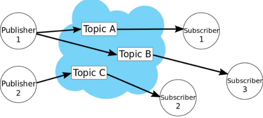
pre-defined topic. This approach puts the data in a central role which simplifies the deployment of intricate distributed systems. The DDS middle-ware also supports quality-of-service (QoS) parameters that can configure the behavior of the data ex-change. A visual representation of a publish/subscribe communication scheme is shown in Figure 3
Figure 3: The DDS publish/subscribe model.
2.2.2 Structure
DDS encourages modularized and well-defined functionality on a distributed system. A list of the entities that compose a basic DDS communication is shown below.
Domain: in order to share data, applications need to be in the same domain. Complex distributed systems can use domains in order to separate different com-munication tasks.
Domain Participant: this entity provides the process with the facilities to par-ticipate in a DDS domain. Through this object, a process may create subscribers, publishers and all kinds data entities that conform to the DDS communication.
Topic: an object that encapsulates several communication publications with a common purpose.
Publisher: a Publisher is an object responsible for the actual dissemination of data.
Data-writer: an entity that sets the data values to be published under a given Topic.
Subscriber: a Subscriber is an object responsible for the actual reception of the data disseminated by publishers.
Data-reader: a Data-reader allows the application to declare the data it wishes to receive (by making a subscription using a Topic, ContentFilteredTopic or Multi-topic) and to access the data received by the attached Subscriber.
2.2.3 Quality of Service
“Quality of service is defined as the characteristics of a network service that bear on its ability to satisfy stated or implied needs to the user of the service”. In other words, a network link must be able to satisfy certain demands from the devices that populate it even under less-than-optimal operating conditions [11]. Some examples of Quality of Service metrics are:
Speed: it is how fast the network can perform one of its functionalities, regardless of the accuracy or correctness of the function.
Dependability: the degree of certainty with which a network performs one of its functionalities given certain expected operational conditions but regardless of its accuracy.
Availability: indicates how likely is a feature of the service to be ready for the users assuming that the necessary resources for the service are provided beforehand.
Reliability: the probability that a network will accurately perform one of its functionalities under stated operating conditions.
Simplicity: the lack of complexity and the degree of abstraction with which the users can access the network’s features.
Security: the robustness against any attempt to exploit a vulnerability of the net-work in order to gain unauthorized access to its assets (i.e. information, bandwidth, etc).
Data Integrity: the capability with which the network guaranties secure data storage and correct transmission.
2.2.4 Real-Time Publish Subscribe Protocol
The Real-Time Publish Subscribe (RTPS) protocol is an interoperability protocol that allows several providers of DDS to communicate with each other. The RTPS protocol is a fundamental part of DDS since it defines the DDS communication packets in terms of the Internet Protocol (IP), thus ensuring that the middle-ware remains interoperable independently of the software implementation. RTPS was first developed in the industrial automation context and was an approved standard by the International Elechtrotechnical Commission IEC as part of the Real-Time Industrial Ethernet Suite [12]. The protocol is a widely used and proven technology
that has been implemented around the world in thousands of industrial devices [13]. The main features of the RTPS protocol include:
• Performance and QoS configuration parameters to enable best-effort and re-liable publish-subscribe communications for real-time applications over an IP network.
• Fault tolerance against malfunctioning nodes.
• The ability to extend and enhance the protocol without hindering interoper-ability.
• Automatic network discovery, connection and re-connection, even when the nodes connect intermittently and/or without any warning.
• Configurations allow to balance the requirements on reliability and timeliness for every data transaction.
• The protocol is modular, allowing resource-constrained devices to implement a subset of the protocol and participate in the network.
• Good system scalability allows the network to potentially scale to a very large number of nodes.
• Type-safety protects nodes from programming errors presented in other nodes. The RTPS protocol is designed to be able to run over multicast and connection-less best-effort way in transport protocols such as UDP/IP.
2.3
Real-Time System
2.3.1 Definition
A real-time System is a system in which its correctness not only depends on the result of its computation, but also in its ability to perform said computation within a given time constraint. In other words, a real-time system needs to perform an operation correctly and in time. Real-time systems are deployed in many fields. Industrial robotics is one of those fields.
2.3.2 Characteristics
Some of the most important real-time properties and parameters are presented in the following paragraphs.
Schedulability: is the property of a real-time system has if there exists a feasible schedule that allows the system to execute all of its tasks within the aforementioned time limit [14]. Vast theory on the means and methodologies for achieving these feasible schedules has been developed over the years [15]. Some of the most com-mon scheduling algorithms are Rate com-monotonic (RM), earliest-deadline first (EDF), deadline monotonic (DM), etc.
Many real-time operating systems support priorities in order to give preference to some processes over others in the case that many tasks are available and ready to execute at the same time.
Execution Time: It is the total time that a task or executing process uses in order to perform its functionality assuming no interference or blocking occurs.
Determinism: it is the grade of predictability that the behavior of a system has. In other words, the output of a deterministic system is one whose outcome can be predicted and does not depend on any stochastic variable [15]. This is a very important real-time property since the analysis and design of a system is based on the modeling and prediction of its tasks.
Latency: it is the time delay between a request and the generated response in a system. Latency is an important factor that needs to be taken into account in order to correctly model and design a system.
Jitter: it is the slight variation in the starting and end times of a real-time task. The presence of jitter in a system can affect its determinism and makes the system difficult to analyze, therefore, jitter is an undesirable trait on any system.
Real-time Distributed System: a distributed system consists of two or more processing nodes that cooperate in order to solve the same problem [14]. When these systems need to comply with strict timing requirements, they are said to be a real-time distributed system.
Variance: in probability theory and statistics, variance is the expectation of the squared deviation of a variable from the mean. in a real-time context, the variance of random sample measurements can tell how deterministic a system is.
2.4
Other terms
2.4.1 Overview
In this section we will cover some concepts that, while they do not have a central role in the development of this work, they serve as the context for this work effort. One of the main reasons to integrate an industrial robot to a local network is to be able to gain a better insight into the manufacturing process. The kind of information that an industrial robot can provide about this process is very valuable for new developments in the field of the so-called Internet of Things [16].
2.4.2 Internet of Things
The Internet of Things (IoT) consists of the latest developments in micro-controllers, embedded platforms, smart sensors, communication technologies, and Internet pro-tocols, working together in order to interconnect devices without direct human
involvement [17]. These devices range from smart phones, televisions and home appliances, to smart sensors, monitoring systems and health-care devices. Another definition of IoT is the collection of sensor and actuators interconnected to computer systems used to monitor and control their operation. Devices primarily designed for human interaction are not considered as part of the IoT [16]. The rate at which we are adding new devices to the Internet is very fast. The IoT promises seamless machine to machine (M2M) communication and equally easy data retrieval from smart devices, which will deliver a new class of “smart functionality” to our objects. Because of its potential benefits, it is expected that the IoT will generate 3.9 to 11.1 trillions of dollars per year by the year 2025 [16]. As mentioned during the intro-ductory section, smart manufacturing and smart factories are a trend that requires industrial equipment to be more and more interconnected, both with their operators as well as with other machines.
2.4.3 Industrial IoT
The Internet of Things in an industrial context is commonly known as “The Indus-trial IoT”. Research on IndusIndus-trial IoT applications is still in an early stage [18], nonetheless, a trend is evident among the research efforts to make industrial robots more connected to its environment (machine-machine as well as machine-operator) which could yield more flexible production lines (the so-called Industry 4.0 [19], see Figure 4 ).
Figure 4: A tight integration between IT and manufacturing systems will bring the 4th Industrial Revolution [19].
2.4.4 Cloud Computing
Cloud computing is a term that describes a computing system that provides a service (data access/storage, applications, CPU power, etc) to a remote client over a network connection [5]. The “shapeless” infrastructure formed by the immense amount of servers that compose the Internet is what is refereed to as “The Cloud”. The benefits that cloud computing brings, both at the consumer and business levels, are very evident. The ability to access virtually limitless CPU power and data,
plus the ability to share information over the network, has had an immense impact in the way we use computers [5, 17]. Cloud services are offered in a plethora of ways to consumers and businesses. On-line storage, office suites, video streaming and driving directions are some of the most familiar cloud services. For businesses, data analysis, business management and monitoring/supervision are some example applications.
3
Related work
In this section we review some of the research works that are related to the objec-tives of this thesis.
While robot collaboration in the context of DDS as the enabling technology is a relatively new topic, there exists other works that have attempted to communi-cate robots with similar frameworks, and more importantly, with similar real-time constraints.
3.1
The Real-Time Publish/Subscribe Protocol
3.1.1 RTPS use in Distributed Systems
First and foremost, we can start by mentioning some of the existing literature re-garding the real-time publish/subscribe protocol used in the context of industrial automation.
On a related work carried out by the National University of Defense of China [20], DDS is employed to encapsulate the communication capabilities of a real-time, scal-able, distributed robotics communication framework. The obstacles addressed with in [20] are similar to the ones that are the focus of this thesis, since the main con-cern is the hard real-time requirements for the dissemination of the data across all the nodes. Whereas the aforementioned work has the freedom to chose the best platform for implementing this technology, with Robot Operating System (ROS) chosen as the basis of their so-called MicROS-drt system, this thesis deals with a legacy system that cannot be easily manipulated of adapted to implement DDS and therefore a software communication layer needs to be implemented. Another key-difference is that the system presented in [20] uses a loosely-coupled link between the different nodes that constitute the distributed system, whereas this thesis imple-ments a completely-coupled system, where no connection drop-out or delay above a tolerance threshold happens.
Limsoonthrakul [21] showcases in his research paper about the usage of of a publish subscribe protocol in another communication framework for distributed autonomous robot systems [21]. We can compare this effort in terms of its limitations and the overall complexity of the system that in contrast gets avoided by using the RTPS protocol in DDS in this thesis.
The prototype system of the thesis will be deployed over Ethernet using a generic switch. Efforts for testing the capabilities of the RTPS protocol over Ethernet and measuring the non-deterministic capabilities inherent of Ethernet have been docu-mented in [22]. To achieve very tight real-time constraints, Open Real-time Ethernet is implemented in that work. This thesis, in contrast, uses the common Ethernet implementation to implement the prototype.
3.1.2 DDS Performance
While this thesis focuses on the performance of a DDS communication in a specific software and hardware setup for the needs of the robot controllers, the performance
of the communication middle-ware has already been analyzed on several works. A survey of DDS and other real-time-oriented communication middle-ware can be con-ducted in [14]. The importance of DDS as an enabling technology in the Internet of things has been claimed in [17]. The performance evaluations of DDS in an industrial automation context conducted in [7] served as the basis to test the ex-perimental setup developed in this thesis. The primordial difference between these research efforts and this work is that the system that is being used as a prototype can be considered a legacy system from the point of view of this thesis, since it cannot be modified to embed the DDS libraries and an additional communication layer is required to make it work.
3.2
Industrial Robotics
3.2.1 Robot Collaboration
Industrial robots usually collaborate in a “hard-coded” way. This means, robots just follow a predefined path programmed by an operator in order to orchestrate a collaborative effort. Enabling robots to dynamically and easily communicate with each other and add a higher layer of abstraction to collaborative robotics has been discussed in [23]. In contrast to this thesis, [23] does not explores the possibility of using a higher abstraction layer in a time constrained environment like this thesis. Another collaboration of this work is that the industrial robots discover each other in an automatic way because of the capabilities that DDS has access to. Therefore, zero-configuration is required in the context of the thesis work.
Other research works focus more in the collaboration of small, non-mission-critical robots. Works like [24, 25] showcase examples of robots collaborating between them-selves in a non-industrial setting.
Other research efforts implement data sharing capabilities in robots for human col-laboration [26, 27]. This thesis proposes a test prototype into autonomous, intelli-gent, robot-to-robot industrial collaboration, which hasn’t been yet fully explored.
3.2.2 Industrial Data
Accessing all the (massive) stream of data generated by a factory as a new paradigm for manufacturing supervision. Researching procedures for using the data generated by a plant as a mean to optimize the energy consumption has been widely docu-mented recently [4, 28, 29]. These works make use of external sensors or add-in solutions to monitor the activity of the manufacturing plant and integrate it into the logistics of the overall business. Using the information available on an industrial robot, in real-time, and specifically having the robot publishing the data itself is an area that has not been thoroughly investigated. In the future work section of this thesis, some possible use cases that are related to this new paradigm are presented. One research work [30] attempts to use information gathered from a ROS-based robot in order to monitor its functional behavior. Fusing this approach with an in-robot DDS-based communication framework could greatly remote monitoring ef-forts.
3.3
State of the Art
Industrial robots usually collaborate in a hard-coded way. This means, robots just follow a predefined path programmed by an operator in order to orchestrate a col-laborative effort. Enabling robots to dynamically and easily communicate with each other and add a higher layer of abstraction to collaborative robotics has been re-searched before [23]. Allowing machines and work objects to communicate with the robots in order to adjust the manufacturing process to fit a customers is another active research topic [31, 32]. Accessing all the (massive) stream of data generated by a factory as a new paradigm for manufacturing supervision. Researching pro-cedures for using the data generated by a plant as a mean to optimize the energy consumption has been widely documented recently [4, 28, 29]. Increasing a robots capability to communicate could also lead to smarter robots or robots that can learn expert knowledge from human operators, as shown in [33]. In this research, a robot is teleoperated by an expert user in order to weld parts with a complicated geom-etry. The robots connection to the Internet makes it possible for the operator to control the robot from a distant place. It is also possible for the robot to learn from the movements and procedures that the expert user performs in order to become a better solder; In this case, a more powerful computer runs the algorithm that the robot executes.
4
Research methodology
4.1
Overview
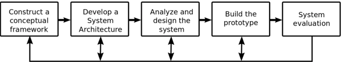
The research methodology used in this thesis is based on the well-defined and systematic approach mentioned in [34] and [35]. After analyzing and contrasting these works with the objectives of the thesis, “System Development” is the research methodology that is employed in the thesis. This methodology strives to answer theoretical questions where the solution is hard to find without a real prototype or where the objective is to apply existing technology in an innovative way. This methodology is a systematic and intensive approach that follows five main steps, as demonstrated in Figure 5:
1. Construct a conceptual framework 2. Develop a system architecture 3. Analyze and design the system 4. Building the prototype
5. Observation and evaluation
Figure 5: The System Development methodology. Note that the arrows indicate that the process can be iterative (it is allowed to go to previous stages if needed).
4.2
Conceptual Framework
A Conceptual framework is constructed by establishing clear research objectives and expected outcomes. The functionality of the system must be defined in a high-level way. Theoretical work must be carried out in order to better understand the research problem and to be able to reach a better result. Aiding and related disciplines must also be defined and studied in this step.
4.2.1 Research Objectives
After connecting several industrial robots and other monitoring devices (such as PCs and tablets) within the same network, we will attempt to analyze the performance of the communication within the industrial robots under different, predefined, testing conditions. Latency over payloads within the local network in which the robots exchange their data is the main parameter to analyze.
4.2.2 Expected Outcomes
Regarding the implementation outcomes, it is expected to have a fully functional data exchange software that can seamlessly integrate multi-platform clients (Vx-Works, Windows, Android, etc) in order to simplify, enhance and monitor robotic tasks. This data exchange is expected to bring the following benefits:
1. The robots will be able to communicate with each other and exchange data. 2. The data of the whole system will be easily accessed and displayed, even in
on-line applications.
On a research level, after designing a system that can accomplish the aforementioned implementation goals, we expect to have answered the research questions of this thesis. In other words, this thesis will provide a good insight, backed up with test results and other studies, about the possibilities of implementing a robot to machine communication based on DDS. Moreover, the thesis will deal with the constraints that this kind of communication would pose to real-time-centric applications while analyzing its performance and weighting in the advantages and disadvantages of choosing DDS for an ABB industrial robot.
4.3
System Architecture
Developing a system architecture is a step of the research that consists in defining the components that will form the system, as well as the way these components work with each other. During this stage, all the constraints for the system need to be taken into account to ensure a successful prototype. A complete section of this thesis is dedicated to an in-depth explanation of the system’s architecture.
4.4
Analysis and Design
Analyzing and designing the system consists on applying technical knowledge about the project in order to devise possible solutions to build the system. In the context of this thesis, the provided hardware will be analyzed and an initial design will be traced
4.4.1 Initial Design
In order to start designing the system, the techniques and technologies that will be used for it will be defined. The hardware that the system contains dictates many of the requirements that must be followed in order to develop a system with said components. For example, ABB robots can only be programmed with the RAPID programming language. Similarly, the robot controller’s operating system and the DDS-based product that will be employed reduce the communication-centric programming language options to C and C++. It is important that the initial design of the system takes into account these imposed constraints.
4.4.2 Time Constraints
Regardless of the scope of the project, the main limiting factor in most thesis works is the time, and this project is no different. Planning the design process needs to be closely related to the amount of time that the thesis work has available. The scope, objectives and outcomes of the project have all been declared after taking into account the time constraints that this thesis will follow.
4.5
Development
As the name implies, this stage is all about developing the prototype that will help to answer the proposed research questions.
4.5.1 Development Stages
The hardware provided already consists of two industrial robots, each one equipped with a robot controller connected to a network by means of a switch. The first development phase will focus on writing the software that is needed for enabling a DDS-based communication between the industrial robots. Developing a robot appli-cation that can send and receive data from the aforementioned communiappli-cation will be the next phase once the DDS-communications is working. After developing this preliminary application, the main priority will switch to measuring the performance properties of the implemented communication between the robots and other parts of the network.
4.6
Observation and Evaluation
By observing and analyzing the developed prototype, one can learn about the ques-tions that were posed as the objective of the research. In order to do this, a series of experiments will be performed. The setup, as well as the results of each test will be logged in different “test cases” that will be reported in the following sections.
5
System architecture
5.1
Overview
The system will contain three main entities: 1. The ABB industrial robots.
2. A central Windows-based computer. 3. Local monitoring devices.
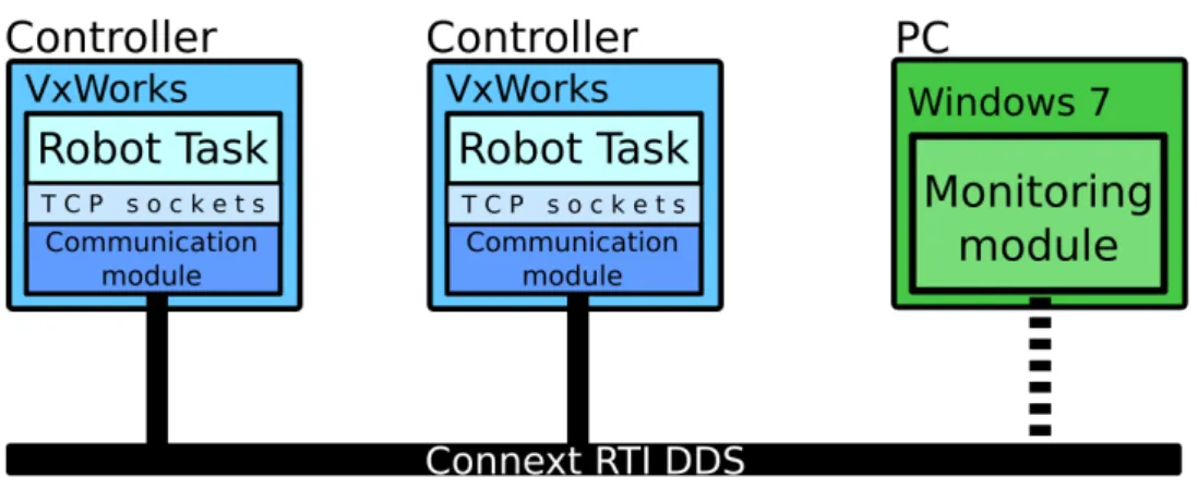
It is important to note that the experiments are performed with only two ABB industrial robots. The main entities of the system are connected by an Ethernet connection that goes through a Cisco 2960 Switch. A wireless access point is con-nected to the Cisco 2960 switch in order to facilitate access to monitoring devices (like tablets or mobile phones). Figure 6 showcases the architecture of the developed system. Many entities of the system are very different from each other, thus, their
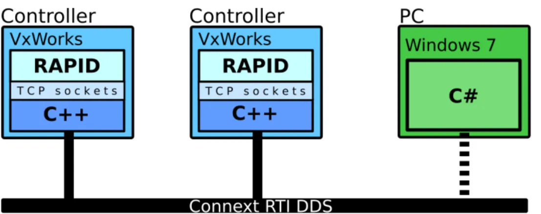
Figure 6: The architecture of the intended system. The node “Robot Task” consists of the commands to be executed by the robot. This module is accessed through TCP Sockets by a communication module, which is where all the DDS facilities are located.
available interfaces, as well as the programming languages in which the software can be written for them, vary greatly. As shown in Figure 7, the Windows 7-based central computer integrates the DDS software using a C# application. This ap-plication also publishes the data to Microsoft’s cloud computing platform, Azure. Since the industrial robot controllers are based on VxWorks, the software is created using C++. The C++ applications on the robot controllers communicate with the robot’s program, which is written in ABB’s RAPID by means of a socket. We will analyze each entity in detail in the upcoming sections.
5.2
The Robot Controller
A Robot controller is the device responsible for the robots correct program execu-tion, motion control and many other functions. The controller’s firmware is based on VxWorks, therefore, C and C++ applications can run on the controller. The robot’s program is written in an ABB’s proprietary language called RAPID. The
Figure 7: The relationships among the entities, as well as the programming languages used to make the software vary between devices.
RAPID programming language provides a high-level of abstraction for commanding the robot. It also provides a set of functions that can interact with other non-robot related components, like a socket-based networking capabilities and inter-process communication message queues.
5.2.1 The Teach-Pendant
ABB’s robot controller has an interface device that can control the execution of the program, the controller’s configuration parameters or even manually jog the robot. This interface is called the “Teach Pendant”. The aforementioned device is used during our thesis work in order to load and resume the execution of both the firmware-related VxWorks programs and the RAPID-based instructions.
5.2.2 The Controller’s Firmware
The robot controller runs on top of a VxWorks installation. This real-time operating system is responsible for deploying the tasks employed by the controller, among other administrative and security features. In this prototype, the controller runs a C++ script that interfaces the RAPID-based program that the robot runs with the DDS publish/subscribe functionality required to communicate with other parts of the system. RAPID-based programs have the capability to communicate with external applications by several means, like Transmission Control Protocol (TCP) sockets. The simplest alternative to connect the RAPID program with the C++ application is to use the aforementioned socket capabilities. This solution increases the overhead and response times of the overall system, therefore, measurements and an analysis of this performance impact is presented in the following sections.
5.3
The Central PC
The central PC is a Windows 7 based computer that runs a C# program that implements the DDS libraries. This computer is meant to issue commands to the robots, as well as logging and monitoring the work carried out by them.
6
Implementation
In this section, we explain how the DDS communication was implemented on the experimental setup used to build the prototype, which served both as a proof of con-cept and as a benchmark for testing the feasibility of a DDS-based communication scheme in ABB’s industrial robots.
6.1
The Base Experimental Setup
Before the start of this thesis work, a basic setup was already implemented using a simple, socket-based, communication. An explanation of this setup, which later was adapted to work with DDS, is now presented. As stated before, the desired network topology that will be tested consists of three main entities:
• ABB robot with industrial robot controller 1 (R1). • ABB robot with industrial robot controller 2 (R2).
• A PC (Windows 7 x64) showing the shared data in real-time.
The experiment consists of a data exchange in order to pick and place a work object on different X and Y coordinates in a shared work area. It is intended that each robot will randomly generate the coordinates of a new position on the plane and will place the object there. Afterwards, the other robot will obtain the coordinates from the first robot, pick-up the object and move it to a new randomized position. The Central computer can subscribe to the data of the system and visualize what the robots are sending to each other in real-time. The algorithm that the robots run for the experiment, compels with the following logic: Once the first robot (R1) picks the work object from a known start point...
• R1 generates random X and Y coordinates. • R1 places the work object in the coordinates. • R1 returns to its home position.
• R1 sends the coordinates to R2.
• R2 picks the object from the received position. • R2 generates random X and Y coordinates. • R2 places the object at the new positions. • R2 returns to its home position.
• R2 sends the coordinates to R1.
• R1 picks the object from the received position.
These steps are repeated until a stop command is issued to any of the robot con-trollers. The communication between this robots is implemented using the the built-in RAPID socket functions.
6.2
The DDS Experimental Setup
The aforementioned functionality of the base setup is ported to a DDS proof-of-concept experiment that showcases the feasibility of running DDS on an ABB robot controllers and use the setup to implement a more advanced communication scheme among the involved entities. Aside from the data exchange between the robots, the system is able to showcase the information being shared through the central computer.
6.3
The Communication Algorithm
This subsection showcases the steps performed by the code written in RAPID (ex-ecuted by the robot) and in C++ (ex(ex-ecuted internally in the controller). It also describes in more formal terms the separation of the tasks performed during the al-gorithm, as well as the alternating order in which the robots and the C++ modules perform their steps.
6.3.1 Robot R1’s Algorithm
Below is a short description of the execution steps that R1 performs. A flowchart depicting the algorithm is shown in Figure 8.
1. R1, the first one of our pair of robots, starts by grabbing the work object from an initially known position, generates a set of XY coordinates randomly and sends them to the C++ module.
2. The C++ module receives the new XY position and publishes it to the DDS domain. After that it starts waiting for a new XY pair to be published in the DDS domain.
3. R2’s execution starts at this point and ends with its C++ module publishing data to the DDS domain.
4. R1’s C++ module detects the published data and sends that to the RAPID program of the robot. It then proceeds to wait for new data from the robot. 5. R1 receives the new XY position, grabs the object, and generates a new set of
coordinates. The object is placed and the data sent to the C++ module. The cycle repeats from step 2, on-wards.
6.3.2 Implementing the C++ Module
Speed was an important factor to take into account when coding the C++ code that executes in the VxWorks 7-based controller. As stated in the DDS distribution’s technical manual, the built-in mechanism that the DDS distribution employs to asynchronously fetch DDS publications through interrupts has an inherent lag that affects applications in situations where speed is a key factor. For this reason, the algorithm was coded to use both the default fetching mechanism (fetching) and a poling fetching mechanism. It is worth noting that the both fetching mechanisms
are employed in the C++ algorithm enclosed in a while loop. The inherent lag that the asynchronous mechanism presents slightly impacts the overall response time of the algorithm, as seen in the results.
The priority assigned to the VxWorks task that serves as our communication layer is 1, therefore it runs with the second highest priority possible. This priority was chosen because it is not desired to impact the performance of the tasks with the highest priority in the controller, such as the motion control tasks, etc, since doing so could lead to severe consequences. There are other controller-related tasks that run with a higher priority, unfortunately, the type of tasks and other information about them is not allowed in the scope of this thesis. What can be said is that the priority of the communication task, as well as the other tasks executing at a higher rate allow the communication task to be executed once every 0.182ms on average.
6.3.3 Robot R2’s Algorithm
R2’s algorithm follows the same logic as R1’s. Nonetheless, since R1 is responsible for starting the data exchange, R2’s algorithm starts by waiting for new information from R1, as opposed to picking up an object. R2 continues the algorithm and performs the same steps as R1 from this point. Figure 9 showcases R2’s algorithm, both the RAPID code and the C++ communication layer. Figure 10 showcases both algorithms running side by side. This allows the reader to easily grasp the communication process performed by the robots and when the DDS exchanges occur.
Figure 9: Flow chart depicting the steps performed by R2’s RAPID and C++ algorithms. Note that, unlike R1, R2 waits for new data first and moves later.
Figure 10: Diagram showcasing the execution of R1’s and R2’s algorithms. The arrows showcase the data exchange, be it a DDS transmission or a local socket transmission.
7
Experimental Results and Evaluation
This section presents the methodology used to test the performance of the prototype setup as well as the results obtained from the different experiments.
7.1
Testing Methodology
The main focus of the experiments is to measure latency against throughput. For a given set of predefined parameters, the prototype setup is programmed to transfer dummy packages from one robot to the other. As the test progresses, these packages range from 10 to 1000 bytes long. Each package is sent 1000 times to the robot in order to ensure a statistically-accurate representation of the latency. First, this section presents the latency of the communication scheme employed in the base experimental setup. Afterwards, measurements on the prototype system are shown, as well as measurements on individual stages of the system. Finally, a comparison between the two setups, as well as the prototype setup with different configuration parameters, is presented.
7.1.1 The Conducted Experiment
The experiment consists in sending a dummy string of an ’n’ amount of bytes. The string starts with ’n = 10’ and ’n’ is increased by 10 bytes after it gets sent 1000 times. The testing message starts from one robot (R1) and reaches the other robot (R2). The second robot replies with the same message and the first robot logs the amount of time it took the string to make a round trip. Figure 11 shows how many messages will be sent. In order to decrease the probability error, every transition is done 100 times. Each experiment of test case is presented in the following format:
Test name What is the test measuring? Hardware Which hardware is involved?
Com. Type Socket / Socket + DDS / DDS-only QoS prof. Reliable or Best effort? (DDS) Read met. Asynchronous or Synchronous. Ext. subs. Subscribers in the topic? (DDS) Str. subs. DDS throughput test (DDS)
Test name As it name implies, it is the name of the test case that is going to be performed. This name is representative on what kind of experiment is being conducted.
Hardware refers to all the involved equipment during the test. Routers and switches as well as other ”secondary” devices are also included. Some tests are performed using a Socket to Socket communication, while others use the complete DDS+Sockets setup.
Figure 11: The amount of bytes per transmission in the experiments. Each transmission is repeated 100 times. Point A and Point B can represent the R1/R2 robots, the Rapid / Communication modules, only the Communication modules, etc (depending on the type of experiment).
Communication Type Specifies the type of communication used during the ex-periment. It refers to one of the three possible tests: Socket (RAPID program to communication layer via TCP Sockets), Socket + DDS (complete system), or DDS only (communication layer to communication layer between robot controllers).
QoS profile refers to the DDS-specific Quality of Service profile that is chosen for the experiment. During this work, the default QoS by the DDS distribution is used. The Reliability is the only aspect changed from the QoS, both Reliable and Best effort tests are taken into account. A Cisco 2976 switch with the default factory settings was used. It is important to note that the switches configuration does not blocks or interferes with the QoS parameters of the DDS distribution.
Reading method As stated before, the DDS distribution can fetch new informa-tion in a synchronous or an asynchronous (interrupt-driven) way. This field in the experiment indicates which fetching method was employed.
External and Stress subscribers The DDS distribution has many testing utili-ties that can be used to measure or cause stress on an application. Two of this tools are the DDS subscribers test and the DDS performance test. The External sub-scribers test creates subsub-scribers that fetch data from the test topic, which is what the parameter refers too. The performance test creates other topics that publish information as fast as possible in order to degrade the network’s performance. The Stress subscribers parameter indicates whether or not an experiment is conducted with the performance test running and shows the magnitude of the payload that the test is employing (in KB).
7.1.2 Data to be Logged
During the experiments, three main variables will be logged:
• The average latency at each payload (from 10 to 1000 Bytes). • The variance that the measurements present.
• The latency of the worst performing case.
As the tests progresses and the complexity of the system grows, there are many dif-ferent parameters that can influence the performance of the overall system. During these experiments, the default QoS profile that is offered in the DDS distribution is used as a base and a comparison between the ”Reliable” and ”Best effort” reliability policies is performed. Finally, the performance of the DDS communication can be hindered by the traffic of the network, so an experiment of a scenario that would be typical in an industrial setup is performed and the impact on the performance of the overall system is logged.
7.2
Socket Measurements
What we are going to measure in this experiment is the average latency that oc-curs on the basic setup that was the foundation of this thesis work; This is two ABB industrial robots with their robot controllers sharing data over a TCP socket connection.
7.2.1 Basic Setup Measurements
On this experiment, the communication happens only between two robots by means of TCP sockets. The performance of this case is offered as a reference point for the future measurements that are performed on the upcoming experiments. Figure 12 shows the simple node-to-node communication that is tested.
Figure 12: Controller-to-controller socket communication. The test program is imple-mented on the RAPID modules from the base system.
The obtained results are shown in Table 1. Figure 13 shows the behavior of the system at different payloads.
Table 1: Socket to Socket Communication
Test name Socket to Socket latency Hardware Controller (2), Cisco 2976 Com. Type Socket TCP on Ethernet QoS prof. Not applicable.
Read met. Not applicable. Ext. subs. Not applicable. Str. subs. Not applicable.
Average Latency 0.58951 ms Variance 0.006866 ms Worst case latency 1.1 ms
Figure 13: Socket communication: Latency vs Payload.
7.2.2 Observations
We can observe from the results that the setup used to share information between two robots has an average latency of 0.58 ms. This latency barely increases as the payload ascends in size. The worst case scenario was a transmission that took 1.1 ms to complete. Both the average and the worst-case scenarios are going to serve as the basis for the comparison of the DDS-enabled system, which is expected to be more flexible at the cost of speed and determinism.
7.3
Complete Setup Measurements
The complete system, as stated before, consists of the DDS link between the two robot controllers plus the local sockets that connect the RAPID robot program with the VxWorks C++ code that hosts the DDS libraries. The test results of this complete system, along with the individual tests of the isolated DDS and VxWorks to RAPID performance are shown in this section. The DDS + Socket measurements represent the “complete” system measures that a real-life implementation of the prototype would have.
Figure 14: The “Default” DDS measurements setup. This setup involves a data packet traveling from the RAPID module 1 to the RAPID module 2, going through the internal UDP Sockets and the VxWorks Kernel Modules that implement the DDS functionality.
The test case, as well as the results obtained from it are shown in Table 2. Figure 14 shows the behavior of the system at different payloads.
Table 2: “Complete system”: DDS + Socket
Test name DDS + Socket measurement. Hardware Controllers (2), Cisco 2976. Com. Type DDS
QoS prof. Best effort. Read met. Synchronous.
Ext. subs. 0. No external subscribers. Str. subs. 0. No stress test.
Average Latency 1.93699 ms Variance 0.04289 ms Worst case latency 4.02549 ms
Figure 15: Socket communication: Latency vs Payload. Note that the new Socket + DDS setup increases the average latency by almost 1.5 ms
The same test is performed but a reliable QoS policy is chosen over the default “Unreliable” one. The average latency increases as we can see from the test case in Table 3 and Figure 16.
Table 3: “Complete system”: DDS + Socket
Test name DDS + Socket (reliable). Hardware Controller (2), Cisco 2976. Com. Type DDS
QoS prof. Reliable. Read met. Synchronous.
Ext. subs. 0. No external subscribers. Str. subs. 0. No stress test.
Average Latency 2.06860 ms Variance 0.15978 ms Worst case latency 4.11859 ms
Figure 17 shows a comparison between two DDS tests where the only difference is that the reliability has been modified in the QoS profile. When compared to the “Unreliable” test , the “Reliable” QoS profile produces a slightly bigger impact on performance as the payload increases. This, among other results, is explained and discussed in following sections.
Figure 16: Socket communication: Latency vs Payload (Reliable). Changing the reliability parameter in the QoS increases the latency by approximately 0.1 ms
Figure 17: Socket communication: Reliable vs Best Effort. The 0.1 ms increase in latency is more evident when comparing both plots side by side.
A comparison of the DDS measurements and the basic socket communication is shown in Figure 18. Some observations that are worth noting is the performance impact that the proposed setup has.
Figure 18: “DDS communication tests with Reliable” and “Best Effort” QoS as well as direct Socket communication.
7.3.1 Observations
The most important comparison between the base system and the new DDS-enabled one is the fact that the average latency has greatly increased. The basic DDS test (default QoS) already poses a significant performance decrease. The modified QoS test that uses a reliable communication furtherly increases the average latency at higher payloads, but most importantly, the determinism of the system is decreased (as seen in the greater variance of the measurements). This increase in latency and variance can be seen in Figure 17. Figure 18 shows a comparison of the two DDS + Socket measurements with the Base system measurements. While this perfor-mance deterioration might seem discouraging, we have to keep in mind that the software structure used during this thesis work did not allowed to implement the DDS middle-ware directly into the robot controller, instead, a DDS communication layer is being employed which greatly degrades performance. The amount of per-formance degradation caused because of the communication layer will be measured in the following tests.
7.4
Communication Layer Measurements
The performance impact of the internal sockets connecting the VxWorks Kernel with the Robot program is shown in this section. The measurement performed represents the time necessary to deliver the packets of data from the Rapid program to the DDS Communication Module and back. Figure 19 shows the modules of the system that are going to be tested.
Figure 19: The impact performance caused by the communication layer is measured in just one of the robots. The packets have to travel from the RAPID module to the Communica-tion module and back in order to log their latency.
All of this happens in the same robot controller. The test case that showcases the settings used during the measurement is shown in Table 4. Figure 20 showcases the behavior of the internal socket scheme that is used in the prototype setup.
Table 4: “Internal socket: Latency test”
Test name Internal Sockets Hardware Robot Controller(1) Com. Type UDP Socket.
QoS prof. Not applicable. Read met. Not applicable. Ext. subs. Not applicable. Str. subs. Not applicable.
Average Latency 0.63656 ms Variance 0.35055 ms Worst case latency 3.64011 ms
Figure 20: Internal sockets communication: Latency vs Payload. Here we can observe that internal socket setup has a considerable impact on the performance of the overall system. It is also worth mentioning that the variance of the latencies increases, as well as the worst-performing case.
7.4.1 Observations
It is evident that , while the average latency among the payloads is relatively small, the impact that this communication layer can have in the worst case scenarios is pretty high. This greatly reduces the determinism of the system and would diminish the areas in which this technology would be applied, as stated before, the DDS technology would need to be integrated at a deeper level with the controller in order to be a feasible feature of ABB’s industrial line of robots.
7.5
DDS-specific Measurements
The latency that occurs between the DDS link (among two robot controllers) and the internal socket link (among the Robot program and the VxWorks Kernel Module) is also measured separately. The latency between robots is the time it takes for a message to go from one robot to the other one, passing through the robot controllers (which log the times). The latency between a robot and its controller is measured by the time it takes to make a round trip from the controller, to the robot and then back to the controller. Again, it is the controller the device that logs the elapsed time. This subsection shows the performance of sending and receiving a packet of data in a round trip among the DDS link. This means that only the VxWorks Kernel Modules in the robot controllers is involved in this process, without sending the data to the robot program. Table 5 shows the test case employed to measure the performance of the DDS-based link between the Kernel Modules. The behavior of this link can be seen in Figure 21.
Table 5: “DDS-only (no robot program): Controller-to-Controller test”
Test name DDS
Hardware Controllers (2), Cisco 2976. Com. Type DDS.
QoS prof. Reliable. Read met. Synchronous.
Ext. subs. 0. No external subscribers. Str. subs. 0. No stress test.
Average Latency 0.85771 ms Variance 0.12692 ms Worst case latency 3.01561 ms
Figure 21: DDS-only test: Latency vs Payload. A slight increase in the average latency but a considerable increment in the dispersion of the samples, which greatly affects the worst-case performance.
Figure 22 shows the performance impact that DDS has over the traditional end-to-end socket connection.
Figure 22: A slight increase in latency can be seen when opting for a DDS-based link over the base Socket communication.
7.5.1 The DDS Performance Test
The DDS distribution provides a command-line utility that can be used to generate DDS traffic on a network and logging information about how much a DDS package takes to reach from a publisher to a subscriber. The tool is optimized to generate traffic that puts a heavy stress under the overall DDS system. Many parameters can be chosen from this tool, for example, the length of the data published, the QoS profile, the publishing rate, etc. Using this tool serves two purposes for this thesis:
• Measure the performance of the Robots under network stress. • Measure the performance of other systems while the robots work.
Figure 23: During the stress tests, the packet of data is sent from the RAPID 1 to RAPID 2 and back. The node Perftest P publishes as much information as possible in order to saturate the network, and the node Perftest S consumes the aforementioned data.
The testing setup, as seen in Figure 23, consists of two computers connected to the same switch as the robot experimental setup. One computer works as a publisher while the other one works as a subscriber. The stress test is carried out with two settings: Publishing and subscribing to a packet with a size of 1 KB and with a packet of 25 KB. Table 6 shows the test case that involves the Perftest stress test of 1 KB, while 7 shows the test case for the dataLength = 25 KB measurements. Figure 24 and Figure 25 show the performance of the experiments.
Table 6: “Stress test, data length = 1 KB, Reliable”
Test name Internal Sockets
Hardware Controllers (2), switch, Win7 PC(2) Com. Type DDS + Internal Sockets.
QoS prof. Reliable. Read met. Synchronous. Ext. subs. Not applicable.
Perftest. DataLength = 1 KB, QoS = Reliable Average Latency 2.3280 ms
Variance 0.3008 ms Worst case latency 5.6381 ms
Figure 24: There is a performance degradation when the network is being used by other publishing and subscribing nodes.
Table 7: “Stress test, data length = 25 KB, Reliable”
Test name Internal Sockets
Hardware Controllers (2), switch, Win7 PC(2) Com. Type DDS + Internal Sockets.
QoS prof. Reliable. Read met. Synchronous. Ext. subs. Not applicable.
Perftest. DataLength = 25 KB, QoS = Reliable Average Latency 2.3128 ms
Variance 0.3098 ms Worst case latency 6.1542 ms
Figure 25: It can be observed that there is a very slight performance degradation when compared to the 1 KB long messages.
7.5.2 The DDS Subscribers Test
The performance impact that other topics have in the prototype setup has been measured in this section. Here, the behavior of the system is examined when it needs to publish and subscribe data alongside other processes that also subscribe to the same topic. The DDS subscribers test tool is an utility that comes bundled with DDS distribution at use that can subscribe to any given topic in order to monitor the information that is published by the other nodes. The utility also has the capability of spawning several parallel processes, therefore, it is possible to connect several subscribers to a single publisher in order to witness the impact that this kind of connection would have on the system. The used setup consists of a computer connected to the same switch as the two robot controllers. The connected computer is running the DDS subscribers test tool with a different number of subscribers, as shown in Figure 26. Table 8 shows the parameters used for this experiment while Figure 27 shows the behavior of the system at different payloads.
Figure 26: The DDS module subscribes and consumes the data published in the topic that the industrial robots use.
Table 8: “DDS subscribers test tool”
Test name Latency measure, extra subscribers Hardware Controllers (2), switch, Win7 PC(2) Com. Type DDS + Internal Sockets.
QoS prof. Reliable. Read met. Synchronous. Ext. subs. 0, 1, 4, 10.
Perftest. 0. Not applicable Average Latency (10) 3.5576 ms Variance (10) 0.1097 ms Worst case latency (10) 5.9982 ms
Figure 27: Latency test with 0, 1, 4 and 10 subscribers. Notice that only the average measurements are shown in this plot in order to increase the clarity.
7.5.3 Observations
In these measurements we could witness the real performance impact that is inherent of the DDS technology under different scenarios. First, we can see that the overall increase of latency is small, as stated in the DDS-only test (refer to Figures 21 and 22). Using the system while the included performance tools are running by publish-ing and subscribpublish-ing many DDS messages significantly increases the average latency of the system. The DDS stress test forces a publishing and a subscribing module to transfer as many DDS messages as possible between each other. The performance degradation in the DDS-link of the robot controllers happens only when a the QoS policy forces the messages to be reliable. The DDS subscribers test creates nodes that subscribe to the topic in which the robot controllers are exchanging data. The subscribing nodes are referred as DDS Spies by the distribution’s documentation. The Spies impact the performance of reliable DDS communications between the robot controllers in a proportional fashion.

![Figure 4: A tight integration between IT and manufacturing systems will bring the 4th Industrial Revolution [19].](https://thumb-eu.123doks.com/thumbv2/5dokorg/4908258.135050/16.892.233.669.632.882/figure-tight-integration-manufacturing-systems-bring-industrial-revolution.webp)