Examensarbete 30 hp
Juni 2013
Synchronization Techniques in
Object Oriented Software
Development Environments
Bringing a Synchronized State among Model
and Code Components in Xtext Framework
Ozan Aksoy
Institutionen för informationsteknologi
Department of Information Technology
Teknisk- naturvetenskaplig fakultet UTH-enheten Besöksadress: Ångströmlaboratoriet Lägerhyddsvägen 1 Hus 4, Plan 0 Postadress: Box 536 751 21 Uppsala Telefon: 018 – 471 30 03 Telefax: 018 – 471 30 00 Hemsida: http://www.teknat.uu.se/student
Synchronization Techniques in Object Oriented
Software Development Environments
Ozan Aksoy
Code Synchronization is the process to achieve an equalized state among code domains. However, the equalization process is not clearly defined. An equal state can be achieved in various forms, such as destroying all irrelevant code parts, or just letting them exist without including them in the synchronization process. For this reason, a synchronization process is depended on its synchronization behavior. This behavior is the characteristics of the process. Additionally, conditions of a
synchronization process have an impact on the realization of the behavior. Behavior can only be realized if the conditions of compared states, environment variables, and abilities are configured in support of the behavior. Thus, it can be said that
synchronization behavior is both the analyzer and the decision maker of a synchronization process.
When a synchronization process consists of a singular synchronization analysis and implementation process for two or more code bodies, then this can also be called a synchronization attempt. A synchronization attempt is analyzed under the provided synchronization behavior in limited, expected and exceptional conditions. Though this analysis, any synchronization attempt can be concluded in the synchronization behavioral expectations.
It was observed that a new synchronization theory is required to overcome the needs for the synchronization mechanisms. For this reason, synchronization as a concept has been researched and two contributions are generated. One of these is to establish a start point for synchronization studies, which is defined in nature of synchronization. Secondly, by using the findings from nature of synchronization, expected behaviors during synchronization have been analyzed as functional
calculations. These functional calculation processes have been classified and they are documented for every classified case. Additionally, a methodology for analysis and design of synchronization mechanisms has been provided. Later, this is used on Xtext Framework.
This research is conducted for a double degree master program in Computer Science in Uppsala University and Software Engineering in Tongji University. The project is conducted in BMW ConnectedDrive Laboratories, Shanghai, China. It is supervised by Uppsala University, Tongji University, and Shanghai based BMW China ConnectedDrive Research Laboratory. It is aimed to satisfy the academic research needs of BMW AG.
Tryckt av: Reprocentralen ITC Sponsor: BMW AG
IT 13 042
Examinator: Ivan Christoff Ämnesgranskare: Ivan Christoff Handledare: Amen Hamdan
Table of Contents
Chapter 1 Introduction...1
Chapter 2 Synchronization Concept ...5
2.1 Issue of Synchronization ...6
2.2 Concept of Modeling in Defining Synchronization ...6
2.3 Entity States and Nature of Dependency ... 10
2.3.1 Dependency between Entities of Different Realms ... 11
2.3.2 Capturing Complex Relations ... 12
2.4 Nature of Relations among Entity States ... 15
2.5 Code Artifacts between Mechanisms and Entity States ... 15
2.5.1 Code Artifact Evolution ... 16
Chapter 3 Synchronization Analysis ... 19
3.1 Analysis of Changes in Code Elements and Code Entities ... 19
3.1.1 Identifying Code Elements and Code Entities ... 20
3.2 Types of Changes on Code Artifacts ... 22
3.2.1 Types of Changes in Code Elements ... 22
3.2.2 Types of Changes in Code Entities ... 25
3.2.3 Changes in Code Entities and Refactoring... 26
3.2.4 Conclusions on Changes inside and among Entities ... 27
3.3 Nature of Synchronization ... 28
3.3.1 Limits of Synchronization Ability ... 29
3.3.2 Desired Result ... 30
3.4 Using Nature of Relationship and Nature of Synchronization ... 32
Chapter 4 Synchronization Behavior ... 35
4.1 Basic Behavior ... 40
4.1.1 Type 1 Basic Behavior ... 40
4.1.2 Type 2 Basic Behavior ... 41
4.2 Complex Behavior: ... 43
4.2.1 Complex Relation Resolution Toolset: Deep Synchronization Methods... 43
4.2.2 Type 1 Complex Behavior... 52
4.2.3 Type 2 Complex Behavior... 54
4.2.4 Type 3 Complex Behavior... 57
4.2.5 Type 4 Complex Behavior: Multi-Response Situations ... 59
4.2.6 Type 5 Complex Behavior: Confliction among Three Major Synchronization Parameters ... 62
4.4 Compositions ... 65
4.5 Reordering ... 66
Chapter 5 Design Methodology ... 67
5.1 Necessary Sub-Mechanisms for Synchronization ... 67
5.2 Methodology for Constructing Synchronization Mechanisms ... 68
5.2.1 Aimed behavior: Behavioral goals ... 69
5.2.2 Overall Analysis of Problem Domain ... 69
5.2.3 Segmentation of Target Domains ... 69
5.2.4 Code Complexity Analysis ... 70
5.2.5 Impact of Change Analysis ... 70
5.2.6 Mechanism Model ... 71
5.3 Major Sub-Mechanisms for a Synchronization Mechanism ... 74
5.3.1 Change Notifier Mechanism ... 75
5.3.2 Entity Relation Tracing Mechanism ... 75
5.3.3 Code Generation Mechanism ... 76
5.3.4 Behavior Decision Mechanism ... 76
5.4 Abstract Schemes for Synchronization Mechanism Design ... 77
5.4.1 Tracer Mechanism Design... 78
5.4.2 Change Notifier Design ... 79
5.4.3 Behavioral Decision Mechanism Design ... 80
5.4.4 Generation Mechanism Design ... 81
5.5 Discussions and Findings on Necessary Sub-Mechanisms ... 81
5.5.1 Discussion on Traceability ... 81
5.5.2 Discussion on Changes in Code Artifacts ... 84
5.5.3 Discussion on Serialization and Representation ... 87
5.5.4 Discussion on Similarity and Equality ... 87
Chapter 6 Applying Design Methodology to Xtext Framework ... 91
6.1 Aimed Behavior: ... 91
6.2 Overall Analysis ... 91
6.3 Segmentation of Target Domains ... 92
6.3.1 Analysis of the Framework for Synchronization Attempts ... 92
6.3.2 Segmentation of the Mechanism Workflow ... 93
6.4 Code Complexity Analysis ... 96
6.4.1 Code Entities in Domains ... 97
6.4.2 Code Elements in Target Domains ... 98
6.5 Impact of Change Analysis ... 101
6.5.1 Limitation Conditions ... 102
6.5.3 Exception Conditions ... 107
6.5.4 Target and Path Selection ... 108
6.6 Mechanism Model: Suggestions ... 111
6.7 Features of Synchronization Mechanism ... 112
6.7.1 Compared States of Entities: ... 112
6.7.2 Time of Analysis: ... 113
6.7.3 Correct decision: ... 113
6.7.4 Implementation of Decision: ... 113
6.8 Findings for Xtext Framework Synchronization Solution ... 116
6.8.1 Findings for Xtext Framework Synchronization Solution for Tracing Mechanism ... 116
6.8.2 Findings for Xtext Framework Synchronization Solution for Changes on Code Artifacts ... 117
6.8.3 Findings for Xtext Framework Synchronization Solution in Serialization... 118
6.8.4 Findings for Xtext Framework Synchronization Solution on Similarity and Equality Calculations... 118
Chapter 7 Conclusion ... 119
7.1 Future Work ... 122
References ... 125
Abbreviations ... 131
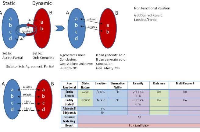
Appendix 1 Functional Relations ... 133
Appendix 2 Nonfunctional Relation ... 135
Appendix 3 Two Static State Conflict Conditions ... 137
Appendix 4 Direction of Change Conflict Conditions ... 139
List of Figures
Figure 1.1 Abstract of a Synchronization Mechanism ...3
Figure 2.1 Synchronization Basics between Two States...6
Figure 2.2 Expected Realm Relation for Domain Specific Language Platforms ...9
Figure 2.3 Structure of an Entity ... 12
Figure 2.4 Method Dependency Example ... 12
Figure 2.5 Entities with Mapping to Properties and Methods Separately ... 13
Figure 2.6 Complex Dependency Relations ... 13
Figure 2.7 Mapping Entities with Captured Dependencies ... 14
Figure 2.8 Evolution of Objects ... 16
Figure 2.9 Evolved States of the Artifacts ... 17
Figure 2.10 Entity Declarations between Realms ... 17
Figure 2.11 Change Among Realms and Correspondents ... 18
Figure 4.1 Functional Relation Synchronization Attempt ... 41
Figure 4.2 Processing of a Nonfunctional Relation Resolution ... 42
Figure 4.3 Synchronization Attempt of a Nonfunctional Relation ... 43
Figure 4.4 Functional Multi-response Cases in Plain State Division ... 45
Figure 4.5 An Example for Plain State Division ... 46
Figure 4.6 An Example Case for a Plain Separate Matching ... 48
Figure 4.7 An Example for Reverse Unified Response ... 49
Figure 4.8 Preparation of the Unified Response ... 50
Figure 4.9 Inferring the Unified Response ... 51
Figure 4.10 Example for Check Step of Type 1 Complex Behavior with Solution 3 ... 53
Figure 4.11 An Example for Resolution of Type 1 Complex Behavior with Solution 3 .. 54
Figure 4.12 Starting Conditions Example for Type 2 Version 1 Complex Behavior ... 55
Figure 4.13 Resolution of Type 2 Version 1 Complex Behavior... 56
Figure 4.14 Starting Conditions Example for Type 2 Version 2 Complex Behavior ... 56
Figure 4.15 Resolution of Type 2 Version 2 Complex Behavior... 56
Figure 4.16 Starting Conditions Example for Type 2 Version 3 Complex Behavior ... 57
Figure 4.17 Resolution of Type 2 Version 3 Complex Behavior... 57
Figure 4.18 An Example for Starting Conditions of Type 3 Complex Behavior ... 58
Figure 4.20 Reversing the Unified Response of a Sub-Entity or Element ... 60
Figure 4.21 Preparation for a Unified Reverse Response ... 61
Figure 4.22 Creation of Reverse Unified Relations during Multi-Response Case... 62
Figure 4.23 Final Resolution of Reverse Unified Relations ... 62
Figure 5.1 Creation of Selective Support over Basic Support ... 73
Figure 5.2 Elements that are required for Multi-Response Support ... 73
Figure 5.3 Complete Synchronization Support ... 74
Figure 5.4 Overview of Fundamental Synchronization Mechanism ... 77
Figure 5.5 External Traceability Information Storage Design ... 78
Figure 5.6 Internal Traceability Information Storage Design ... 79
Figure 5.7 Basic Design of Change Notifier Mechanism ... 79
Figure 5.8 Basic Design of Synchronization Decision Mechanism ... 80
Figure 5.9 Basic Generation Ability Mechanism Design ... 81
Figure 6.1 Mechanism of the Xtext Framework. ... 92
Figure 6.2 Linear View of Code Generation Mechanism ... 93
Figure 6.3 Expected Actions in Linear Workflow ... 94
Figure 6.4 Clustering Correlated Workflow Members ... 95
Figure 6.5 Phases of DSL Development in Xtext Framework ... 96
Figure 6.6 Domaın Model and Model Code ... 102
Figure 6.7 Domain Model and Generation Templates ... 103
Figure 6.8 Model Code and Generation Templates ... 103
Figure 6.9 Relation of Three Target Domains ... 104
List of Tables
Table 3.1 Entity and Element Segmentation ... 20
Table 4.1 Chart of Functional Calculation Parameters ... 37
Table 4.2 Chart of Nonfunctional Calculation Parameters ... 38
Table 4.3 Example Case for a Functional Relation ... 41
Table 4.4 Example Case for a Nonfunctional Relation... 42
Table 4.5 Stating Conditions for Type 1 Complex Behavior ... 52
Table 4.6 Interim Step during Resolution of Type 1 Complex Behavior ... 52
Table 4.7 Starting Conditions for Type 2 Complex Behavior ... 55
Table 4.8 Calculation Conditions during Type 2 Complex Behavior ... 55
Table 4.9 Starting Conditions for Type 3 Complex Behavior ... 57
Table 4.10 Converted Nonfunctional Resolution Step Conditions... 58
Table 4.11 Secondary Nonfunctional Resolution Step for Type 3 Complex Behavior .... 58
Table 6.1 Sample Code for Code Entities ... 97
Table 6.2 Same Code for Code Elements... 99
Chapter 1 Introduction
Software can be described as an evolving system. At the first phases of software development, most of the effort is spent on the documentation and the design of the project [1]. On later phases of development, the design began to lack the consistency with the changes of the implementation level. As it can be seen from the literature review of [2], these consistency issues can manifest itself throughout the development process in many forms, and identification and solution of these changes are resolved by using mechanisms that provide traceability of the artifacts and analysis of impact of the changes on the code and on the model.
With the introduction of the Domain Specific Language (DSL) frameworks, it can be stated that there is a challenge at tracing the changes from the model to the generated general purpose code. As an example, imagine that the defined DSL has been used to write a program for its domain solution. The real usable code will be based on a modeled object schema, which is created in defining the DSL [3]. During the development process, there will be a need for providing consistency and maintenance on related code bodies in the development framework [4]. From the observed frameworks such as Xtext DSL development framework on Eclipse development environment [5], JTL as explained in [6], and Rational Rose Modeling Environment [7], such a workflow was abstracted to following steps;
A base for a domain model to be designed and created
A workflow to generate an environment that uses the designed model
A workflow to map and generate the platform code from the environment that holds the domain specific language code.
And a target location to extract the workflow result(s).In the given structure, target issue would be to find a solution for synchronization of changes among layers in the workflow.
As it sounds simple, it can be said that there are many aspects of the synchronization issue. First of all, we must understand the problem correctly. What we are trying to achieve here is creating a theory that will then be used as a guide to create the synchronization mechanisms. To achieve this target, one must understand the synchronization on object based environments. This understanding enables to create the analysis of the synchronization nature and opens the way for synchronization solutions in environments that are based on object oriented design.
two steps have been conducted. Firstly, concepts in modeling have been studied and, the composite features of the modeling were used in determining the structures of the code bodies. Secondly an analysis of synchronization attempts in object oriented development frameworks is conducted. This was achieved by a research thought the studies on the field, relations of objects as models, and functional calculations. Via these two studies, a new form of synchronization system has been formed.
It can be said that “synchronization” or “code synchronization” is born out of a process that occurs between evolving structural states of corresponding code bodies. However, this synchronization process has to be configured in order to behave the way that was initially desired by the user. This necessity is born because two states of compared code bodies can achieve a synchronized relation in various ways. This can include loss of information, partially equalizing code bodies to each other, etc. Therefore, behavior of the synchronization process is a key factor that determines the outcome.
To achieve such classifications, synchronization process has been divided to different conceptual steps. These are synchronization attempt, synchronization behavior, and synchronization methodology. Throughout this research, a synchronization attempt is used to mean a singular synchronization process that involves at least two compared code bodies. It is concluded that a synchronization attempt carries a special nature. This nature is used as a defining concept on how the synchronization is analyzed and implemented. Moreover, it is used in defining the synchronization behavior.
Synchronization behavior is the logical process that calculates the characteristic of an outcome from a synchronization attempt, and it also tries to find the way that the synchronization attempt can be realized. Then it compares the possibility of whether the synchronization attempt is achievable in the desired characteristics or not. This behavioral analysis is achieved via functional calculations, comparative techniques, and synchronization tools that are created from basic cluster manipulations. These various behavioral aspects are classified in a hierarchic structure, which leads to a constant focus on simplifying the condition of compared states to a basic, calculation friendly form. It was observed that these simplified forms are also becomes more synchronized with each other.
Beyond behavioral aspects, there is a need for a general analysis and design methodology for setup of the behavior and the synchronization mechanism. This need is tried to be satisfied via a synchronization design methodology.
Synchronization methodology is an analysis and design process that is used in applying synchronization behavior to the target environment. Synchronization methodology is interested in how to realize the mechanism as a whole workflow. Therefore, it is interested in
five major issues that proclaim on synchronization attempts. Synchronization methodology can be used in realizing various levels of behavioral capabilities. Such a classification is done in a step by step evolving manner. Each step includes an increased behavioral ability. These behavioral abilities are discussed in synchronization behavioral tools.
In this research, it is claimed that synchronization attempts have five major issues. Synchronization methodology tries to find answers to these five major questions in realization of a synchronization mechanism. These are:
(1) How to relate the correct code parts to each other?
(2) How to generate the equivalent code in correlated code domains? (3) How to understand the changes on the code domain?
(4) How to understand which part to change to reflect the changes on corresponding domain?
(5) How to conduct the synchronization implementation decision?
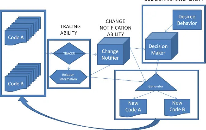
From the five major issues of synchronization, a synchronization mechanism can be summarized in four abilities. These are:
Tracing Ability: Used in relation of code parts and storing or extracting this relation information
Change Notification Ability: Understands and Notifies about the changes on related code bodies.
Generation Ability: Checks whether if equivalent code can be generated, also implements the decided behavior.
Decision Making Ability: Analysis the whole process and decides the outcome and implementation decision.All these sub-mechanisms are used in creation of the desired outcome and they can be merged to each other or they can be divided within each other depending on the framework that synchronization design methodology is implemented. However, in this research, their basic abstraction is aimed to resemble these four sub-mechanisms. Throughout these classifications, intertwined interests of sub-mechanisms are taken in steps of design and development, which leads to less confusion during the implementation of synchronization behavior.
Since analysis and design of the synchronization mechanism is the main focus of this work; in this research, decision making process and reaction to impact of change is intensely studied. Code bodies in a development environment are divided to basic elements and more complex code entities. These entities and elements are discussed and analyzed, and they are mapped to a functional relation calculation process. Hence, a new decision making process has been introduced. This process is constructed via the influence of functional and nonfunctional relations between two domains, and it is used in providing a holistic outcome. Via these calculations, characteristics of a synchronization attempt can be analyzed prior to its implementation. Other issues of synchronization behavior have been discussed and related information from related fields of research has been provided as discussions.
This research starts with providing a discussion on synchronization as an analysis of the issue. A novel view of synchronization process has been provided with relation to development environments and domain specific language development processes. Outcomes of this synchronization analysis have been used in construction of synchronization behaviors. These expected synchronization behaviors are divided to different types. Moreover, tools for solving complex behavioral processes have been provided. On the following, a documentation methodology has been presented. This methodology aims to create a design pattern application which centers on using the synchronization behavior as the brain of the synchronization mechanisms.
Chapter 2 Synchronization Concept
In this section, what is understood from the synchronization in the thesis will be explained. This explanation is a declaration of the writers own design for theorizing synchronization. Influence for these explanations can be found in discussions on relation of sets [8] and bidirectional relations [6]. Moreover, entity relations and dependency concept among related entity states are influential for the synchronization analysis and they are documented in this section.
In order to comprehend the synchronization analysis, issue of synchronization must be explained in the conceptual level. Understanding the issue of synchronization provides the basis to understand the fundamental nature of two synchronization implications. These two fundamental concepts are nature of synchronization and nature of dependency. Nature of synchronization is the fundamental variables which gives the characteristics of a synchronization attempt. Nature of dependency is about the relations among code artifacts that impacts the work and integrity of the code. Thus, nature of dependency creates the limitations and relations of a meaningful synchronization process. Additional to these two fundamental concepts, types of changes that can occur on the code body is studied with the goal of achieving a concrete classification of reasons for synchronization. After comprehension of these three topics, synchronization behavior is possible to be constructed with foreseeable outcomes, thus leading to possibility to analyze the synchronization implementation within a synchronization attempt.
It must be noted that the concept of synchronization that depends on different levels of code body complexities with different hierarchic order was provided from the fact that interested target environments are object oriented.
Understanding the synchronization concept is the entry point for a synchronization analysis. In the following chapter which is dedicated to synchronization analysis, nature of relations and segmented identification of code body is explained. Later, by using the information that is provided in previous sections, nature of synchronization factors is explained. Finally, conclusions from these intertwined concepts are tied as a conclusion in order to be used in construction of the .synchronization behavior calculations.
2.1 Issue of Synchronization
In this work, synchronization is understood as creation of an equal state between two different entities. These entities are aggregated clusters of sub-entities. Sub entities can be in two forms. These are complex and basic. Complex sub-entities are structures with modular phases of construction. On the other hand, basic entities are simpletons with no other sub-level complexity. Code entities will represent large scale and singularly identifiable code bodies, such as object classes, while methods and properties will be referred as code elements. This classification is possible in the fact that code elements are the carriers for the behavioral descriptions for an object. A behavioral code body is a set of functions and problem solving descriptions within a code element. The division for code elements and code entities lies in the concept of Modeling.
2.2 Concept of Modeling in Defining Synchronization
Modeling concepts and Meta Modeling has leaded to necessity for tracing and maintaining the relation of software artifact, which lost their relation with their model definitions during development process [9]. Synchronization process does involve this
evolution; however, it expands this model to code artifact relation via its nature. Synchronization is linked on modeling about which parts of code body are related to each other and what structural limitations do they bring which can be used in creation of equalized states of code.
A software model is a skeleton of a real world idea that can reflect the structure of a logical entity. A software model underlines the identification and relation of the code artifacts. These code artifacts are built on attributes and parameters. These attributes and parameters carry the behavior of the code artifact, which is the logical workflow that methods use when they are called, or when parameters set as they are fetched. [4]
On the other hand, a model is a hierarchic structure which makes it possible to trace in a hierarchal form. This allows providing structural limitations on the code artifacts. Hence, it is both a defining and limiting context. [10]
Code parts that are the fundamental carriers of the behavioral aspects owns different characteristics compared to hierarchically higher, thus more complex code bodies which owns and uses them. Same behavioral result can be achieved in different logical structures, and it uses different forms of tools to achieve the same behavior among different platforms. This fact makes it difficult to realize a equalization of the behavioral code structures. [11]. However, a Meta Model which defines the model itself can be created. This Meta Model is not interested in the behavioral aspect of the code body, but it can target the limited and foreseeable order of a code artifact. [12]
Moreover, studies that researched the impact of change on behavioral code have found out that such and impacts are mostly derived on consistency of the declared dependencies within the code part, and it also impacts the higher structures. This results in decreasing the importance on direct need for equalizing the behavioral code parts. [13]
For all these reasons, methods and properties of the code artifacts have been declared as
code elements in this research. This naming signifies that they are the end of a hierarchy
within the mapped structure of a code body. Code bodies that are in higher hierarchic order are defined as code entities, meaning that they are mapped in a definable, capsulated structure, and they are ready to equalize to a common form.
A secondary effect of of modeling is division in characteristics of code relations. Models are structures that can be transformed to each other and to other types of platforms. However models do not need to carry code elements, they just need to define their existence in the code artifacts. [14]
Thus, two outcomes are achieved:
(1) Code elements act as a sub-entity which carries an identifier. Hence, it can be stated that all code elements are a type of code entity, however not all code entities are code elements
(2) Similarly, a model can define a code entity; it can be transformed into other equivalent models by mapping the definition that it carries. Also, a plain code body that is written in platform specific languages such as e.g. Java or C# carries an embedded model structure thus a model definition can be deduced from them. However, model definition to code definition has a dictating and clear definition for the code body of the implementable platform specific code, while plain code structure that carries the code elements has an accepting and mirroring nature. Thus, a relation of model to a model, model to a source code,
and source code to another source code differs according to such a relation nature.
Therefore, in order to catch such relation characteristics, a model realm and a code
realm have been introduced in this research. A code entity can have a domain that resides in a
model realm or a code realm in relation to its corresponding domain. Same is true for the corresponding domain. A relation among model realm to code realm is different than a model realm to model realm, or a code realm to code realm relation. Moreover, same code domain can act differently according to direction of the dictation relation.
Introduction of modeling and model’s relation to its reflected code correspondent is very significant during designing and implementing the limitation conditions and expected conditions of two code bodies which act as realm to realm pair. The direction, the structure of the model relevance, the Meta Modeling that underlines the model itself, open ways to impact such relations in various fashions. This gives a significant relational characteristic to a code body in relation to its corresponding code body, which may reside in an opposite or a similar realm characteristic.
Such a division is most meaningful in built up for a synchronization analysis of a domain specific language. This is because, in current trends, a domain specific language has a workflow that carries a Meta-Model, a Model, a Code Generation Description, and a Generated Platform Specific code that is for final implementation [5] [3]. Realm
specifications define the characteristics of limitations, expectation and exceptions of the
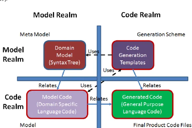
relation and thus the synchronization process. In general, realm relations for a domain specific language are similar to Figure 2.2:
For singular model to code relations such as UML to source code, lower part of the Figure 2.2 is satisfactory. A model language that explains the definition of the code artifact is in dictating relation to code artifacts which acts as the source code, thus they are acting as
model realm to code realm relation. For an example case, this means that the UML model does provide the structure and generated code must follow the model, and the synchronization from code to model is limited to code parts that does not include behavioral code bodies of code elements that resides in code realm. On the other hand, a domain specific language grammar to developed domain specific code relation is similar to top-down left part of the same figure. This time previous model does behave like a source code and Meta Model owns the characteristics of a model code.
Another notable issue is on code realm to code realm and model realm to model realm relations. In the case of Figure 2.2, this is true for code generation templates and model codes. They behave in code to code relation. For a counter example, model to model relation can be mapped between two different model structures, such as XML schemas and UML descriptions [15].
When relation is code realm to code realm, their dependency is not on the reflection of the structural changes. However, these two domains use each other without dictation to one another. Thus, the impact of change on one domain would only impact the usability of the resources, and it will not create a structural inconsistency, but a workflow failure. On the other hand, when relation is model to model, then the code bodies must reflect each other, thus dictating to one another. Unlike code realm to code realm relation, a change on the one
domain must be reflected on the corresponding structure of the co-domain.
It must be noted that, model to code and model to model relation is reflected though the relation of “Relates” and code to code relations is reflected by the term “Uses”.
2.3 Entity States and Nature of Dependency
State of an entity is a snapshot which captures the declaration of the entity itself including the condition of its elements. This declaration is a record of all significant information which describes the entity itself. Hence, it can be referred as both the map and the scheme of the “idea” that construct the entity from a model as a type of model. Action of synchronization can occur between states of the same entity, or between states of different entities. However, firstly the nature of these relations must be understood. In order to achieve this, one must look to the structure of the entity relations in the light of nature of dependency. In order to synchronize the entities, desired state of an entity is compared with one or more entities. Simplest forms of synchronization can occur between such two different states. During an attempt to create equalization between two states, one must clarify the “Limits of
Synchronization Ability” and “Desired Result. These two major concepts are combined in one
topic called as the nature of synchronization. Assumption is that, the most desired
synchronization result is a condition which keeps all or most of elements and creates complete equal state among entities. These two aspects of synchronization nature are results from the
impact of change that occurs via any change that appears on the code.
An attempt to synchronize the elements must assess the condition of change in elements. Assessment is needed to understand the possible impact of the synchronization to elements of entities. This is not the nature of the entity as a whole but rather the nature of elements as a sub-entity. In order to satisfy this requirement, elements are needed to be assessed by conditions that are selected as requirements by the user of the mechanism.
When they are alone, objects are not useful software entities [4]. Therefore it is a necessity to create relations between objects. Relations of conceptual entities were observed from relations of real objects according to [16] and [17].
However, creation of relationships also leads to the issue of dependency. In the observation of this research, it has to be noted that synchronization of the software artifacts in different fields are affected by this relationship nature of the objects. Relationship nature identifies the nature of entity states. It does this by dictating the necessities for consistency among entities. This is an outer dictation factor. When compared to the action of declaring an entity as immutable, it is not constant as such an action, but it changes as dependencies as
they vary in software evolution process.
2.3.1 Dependency between Entities of Different Realms
In the context of this research, dependency is seen as an important point to figure out in the issue of synchronization. As pointed out in [9], objects are code artifacts that are capsulated in the string form. They exist with their properties and operations in this form, thus enabling more generalization. This is also the foundation for the modeling concepts [18].
In a model, class descriptions can be seen as entities of various forms. They can be either independent or dependent. Such a dependency can be in many forms [19]. However, the model is still in the form which will be in context of representation of the object, although is hold in a textual form. These textual representations of an object include various attributes and operations. In order to make them comparable to each other, we can declare both methods and attributes in property declaration. In this research, such a simplification is considered as extending the classification of object properties.
Properties have specific features which makes them different from each other. These differences vary according to the perspective of the comparison. It must be noted that the capability of the comparison mechanisms are directly affected by the data that is collected about the properties and the entities.
In Figure 2.3, we see a mapping of model and its entities. In this figure, all elements in the namespace are seen as properties of the class, including methods. We can state that if we declare classes as entities of a model, all attributes and methods are sub-entities which assemble the class. In the case of Figure 2.3, we declare all sub-entities as textual forms without trying to catch underlying the semantic mechanisms. Main reason for declaring such a simplification is about the complexity of underlying logical mechanisms. Also, in many cases this might not be relevant to the textual similarity. [9]. Thus, these final sub-entity
declarations of the complexity hierarchy are the code elements for this research.
When we look at the issue of synchronization in the entities and their extended properties perspective, it becomes an issue of correlation among extracted entities and properties of the model, and the generated code. However, such a perspective requires a solid mechanism where the design and the generated implementable code become comparable. This would also mean that, the structural differences in the generated code will be unified in a comparable model with the design model.
Therefore, as entities are assembled from the properties of various kinds, models are assembled from entities, where each of them is in model declaration. Changes in the model have an impact on the design and the generated code. This impact varies greatly on the
effected entities of the model. A major change in one entity of the design might be less effective in comparison to an impact of several smaller changes in several entities. The opposite can be true for different situations. This is heavily related to semantic dependencies of the properties. [6]
Additional to the work of Cicchetti, Di Ruscio, Eramo, and Pierantonio [6], examples of similar approaches in creating a comparable replication among realms can be found in the works of Alves-Foss, Leon and Oman [20], Ratanotayanon, Sim and Raycraft [21], and Diaz-Pace, Carlino, Blech, Soria and Campo [12]. In most of the works, method declarations are also included in properties of a class. However in OMG specifications properties are defined as the attributes of the class, and they do not represent the operations/methods of a class [22].
2.3.2 Capturing Complex Relations
There is a conceptual clash on the definition of properties in this concept. Properties are indeed structural features of a class [22]. For this reason methods such as Accessors and isKindOf are applied on them to achieve desired encapsulation features for an object. Methods are the behavioral features of an object. However, methods are also declared and they are also indexed in the namespace. Moreover, they are accessed by a method notation after an instance of an object is created. Some of these sub-entities are dependent on each other as it can be seen in Figure 2.6.
Alternatively, they might be dependent to other sub-entities of other entities. This is usually represented though more abstracted manner via dependency representation between entities. However, in the implementation phase, dependencies of entities can be directed to sub-entities. This does not have to be on single property and method. As methods get more complex, we can say that more properties will be related with some kind of relation characteristic.
Figure 2.3 Structure of an Entity
We know that two or more classes can be depended on each other in order to function as desired. These are usually abstracted as semantic relations at the first phase of modeling. Semantic relations as associations are weak compared to other type of dependencies [4]. Among weak association dependencies, there might be more concrete relations between classes such as inheritance, generalization, and aggregation [22]. Additionally, analysis of the classes can be used to decide the multiplicity of the class. This denotes the multiplicity feature of class relations [4].
Basically, if we separate the properties and methods in our sub-entity declarations, we are able to catch more complex structures that are underlines in the model. Additionally, for a concrete code generation facility from the model, there must be a well-defined model at the first place. In this well-defined model, relations would be strongly mapped to each other. This mapping is similar to clusters with elements of their own. When a code body is analyzed and it is separated by the level of complexity, it becomes a layered overview which links to
matched level of complexity on other compared state of itself or another entity state. In a case
that is not well structured, code generation can work, but it would not be successful in creating functional code. Additionally, the model representation will fail to capture the fundamental functions of the code structure. [5]
Figure 2.6 Complex Dependency Relations
The reason we discuss the abstraction level of the entities is related to the capacities of a synchronization mechanism. If we create more complex and detailed mapping mechanism in model to code and vice versa, it has the capacity to support more intelligent synchronization though the limitations that the concrete model form obtains. If one would only define a property mapping and declare all elements of an entity in name declarations, it will not be capable of understanding the dependencies in the semantics. But, understanding and correcting dependencies within the semantics requires well-structured model and generation body, which is much harder to implement on practice, harder to automate and it will need to include abilities to parse much of the code body to create the relational links. [23]
If one aims to reflect the changes in the code that is generated from the model back to the model, it is claimed that the impact of the changes in the generated code does not always have a major impact on the design. It is stated that most of the changes that is analyzed in the generated code “realm” does not need to reflect back to the model at all. A detailed study on the effects of changes in code-to-design relation can be seen in the work of Hammad, Collard and Maletic [13].
Nature of dependencies is deduced from the findings that are declared above. Thus, one
of the two major factors that affect the decision mechanism and the end result of the synchronization attempt is the Nature of relations which is built in correlation to nature of
dependencies. In this work, Nature of relations between two entity states is identified to be Figure 2.7 Mapping Entities with Captured Dependencies
similar with cluster relations in mathematics. Thus, in this research, they are named in the same manner.
2.4 Nature of Relations among Entity States
Nature of Dependency can be briefly explained to be causing that all dependent objects relate to each other in a manner in which:
Direction of change dictates
And resolved dependency is mapped.Therefore, similar to create cluster-like mapping to understanding of functions in mathematics, code entity states are analyzed in four different states to each other which are inferred from two factors. These are Functional Relations and Nonfunctional Relations. These two forms of relations among entity states are collectively named as Nature of
Relations.
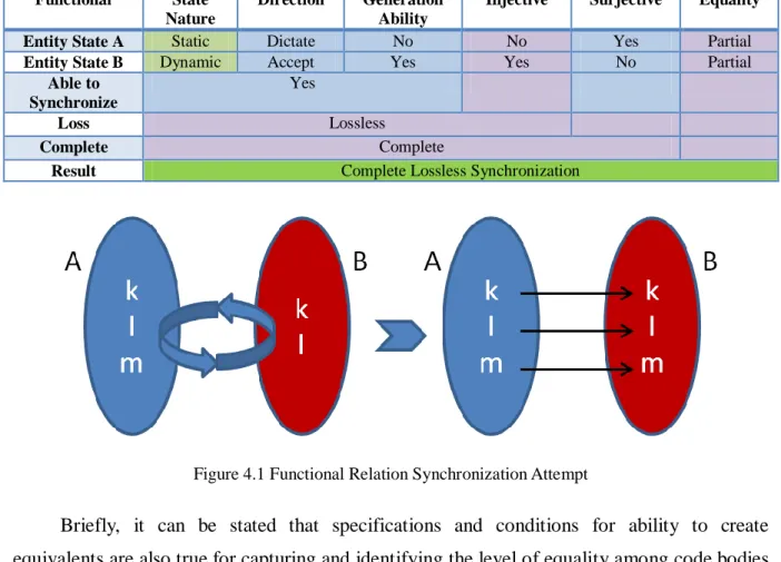
Functional relations that obeys the rule of function mappings fits into
Injective-Surjective nature of sub-entities. Thus, a relation that is both injective and surjective at the
same is Bijective. A resulting bijective relation without loss of information is the most desired
outcome for a synchronization attempt. More detailed explanation for such relations among
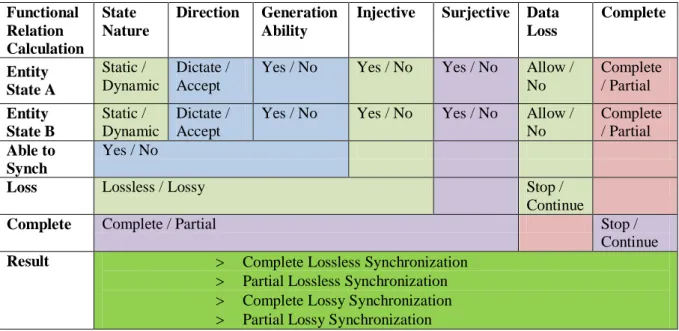
clusters can be found in [8]. Basically put, in this research, dependency relations are modeled as clusters and then relations are created from analysis of the relation as functions. Functional relation examples have been provided in Appendix 1. Significance of a functional relation comes from the fact that all elements of a domain have a correspondent in a co-domain. Thus, all elements that are included in the process can be mapped to a corresponding element or a sub-entity.
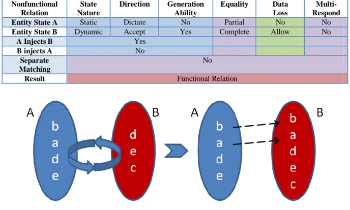
In a direction of relation from one entity state to the other, when sub-entities cannot be mapped to functional relations from the starting direction, this means a domain cannot relate all its members to its corresponding domain in functional fashion. Sub-entities that cannot be mapped in a functional relation are called nonfunctional relations. Thus, relations that do not fit into the provided example situations in Appendix 1 are identified as nonfunctional relations.
2.5 Code Artifacts between Mechanisms and Entity States
in order to create synchronization among the code artifacts, we must first encapsulate their state and find their matching correspondents in compared entity state. Hence, in order to identify code elements and entities between changing states, one must implement a specialized mechanism to the framework. These types of mechanisms are named as
traceability mechanisms.
If one wants to create equalization, then most basic need is to identify and track the related entities and code elements. According to [24], in general, code tracing is used in software maintenance, impact analysis and reuse of existing code. However, this time we must enhance this ability to fit the needs of synchronization.
Synchronization ability specifications and tracing ability specifications are directly relate to each other. In order to synchronize any code body in the flow of the development, synchronization mechanisms have to create an encapsulation that refers to the related code bodies. In this research, the theme of entities and elements is used. However, in any definition, code entities should be identified and related to each other for healthy comparison.
2.5.1 Code Artifact Evolution
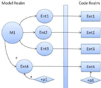
As it can be seen in Figure 2.9, an artifact description changes to different states during a software development progress. Object X has its initial state that is depicted as state X, which has changed to state Y in time. Unchanged sub-entities of software artifact exist in the intersection of two artifact descriptions. An area that reside in state X either corresponds to areas in state Y but they are not recognizable, thus they cannot be matches as the “same”, or state Y has obtained new sub-entities that do not relate those of state X [10]. These matches are available by using tracing mechanisms. [2]
By altering Bunge’s ontology, which is also explained in [9], to fit entity-element definitions, we can reach to the evolution of the code and its traceability. Where X = < x,
P(x) > and X is defined as a unique entity, then E(X) is a collection of code elements
(properties defined as elements). Also, let’s say there is entity Y, correspondence of entity X, which changed in development phases. Where m is the matching elements of evolving objects, intersection depicts the domain of m.
Unmatched defines the element states that are altered, added or obliterated. (1) In Ran(X) = E(Y)
(2) Unmatched(X) = E(X) - Dom(m) (3) E(X) is all identified properties of X
(4) And Dom(m) is all of the elements that are unchanged. (5) Unmatched(Y) = E(Y) – Ran(m)
(6) E(Y) is all identified elements of Y which is in range of X (7) And Ran(m) is the range of Dom(x) which correlates to Y.
In a traceability mechanism that would regenerate the lost tracing link, basic evolving system function is as below:
(8)
For
Among individual elements, one to one similarity search depends on (9)
In order to make this formulation work, one must also apply a similarity recognizer. However, this similarity recognizer mechanism can be overlooked in the cases of tracing have been successfully completed, such as behavioral code bodies, as discussed in [13]. In the cases that the similarity catcher is applied, it should identify the
Figure 2.9 Evolved States of the Artifacts
textual elements and this function can be implemented to various forms.
Evolution of the code directly responses to the needs of the synchronization mechanisms, however catching similarities between the software artifacts are a dynamic challenge that changes among environments. As such, entities of this research are a direct relevance of Bunge’s ontology: Actually, entities are declared as substantial individuals with
properties of their own. These properties will change in time, as development continues. If object declaration is dependent to model and the corresponding
generated entity declarations is altered by developers in later phases of software development,
then traceability is needed. [11]
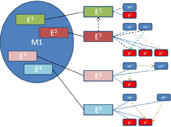
In Figure 2.11, models and textual software code that related to them has been depicted. Model elements reside in model realm while code elements reside in code realm.
A model holds the descriptions for a code entity. A code entity in a model realm is actually a class description. It is an interface or similar scheme that holds the structural components. However, code realm includes both the realized entity code bodies and the expressions that implement the behavior for the software. [14]. Software evolution is a perceived reality which occurs throughout the software development [23]. However, code entities and code elements evolve in different fashions. If we are aiming for a software system that is consistent after the change which might occur at one point of the software development as evolution, we can say that this is also a process which goes thought some steps that is linked to each other via some type of relation(s) between the states of the software product.
In conclusion, a segmentation of the software development phases and separation of target domain are possible within development process. During this process, code elements and code entities are defined, used and changed, destroyed or replaced. This requires classification of code bodies and providing them identification. Hence, it is possible to build the mechanism which can provide the information that nature of synchronization can be used.
Chapter 3 Synchronization Analysis
In this section, code bodies of the code artifacts are analyzed in the light of the information that is provided in chapter 2. As a result, code elements code entities are separately handled because of their different behaviors in the synchronization processes.
In the following, types of changes that can occur on code elements and code entities are identified and their characteristics are used in finding the necessary abilities for reflection of the changes. By using the study of the types of changes and the nature of dependency, nature of synchronization has been identified and explained.
3.1 Analysis of Changes in Code Elements and Code Entities
One can see the code entities as software code body with a segmented part which aggregates together to form the entity. These segmented parts vary in complexity. In order to get the elements of an entity, code body must be analyzed.
Object oriented design features and object relations of Java Platform will be majorly used in this analysis. This is because that platform forms a significant influence on the interested development frameworks.
Because of object oriented design patterns [4], one can correlate the design patterns for a synchronization attempt. Moreover, object oriented patterns bring a beneficial limitation to things that need to be considered while a synchronization attempt, thus easing the burden of synchronization decision mechanisms. Some major limitations include the limitations on file structure, and manifestation model of projects.
Limitations on file structure’s state shows itself is in class declarations. Unless nested, class declarations cannot be in the same location as a file. All classes would have various depth and complexity for the statements and expressions that they hold [25]. When interfaces and abstract classes and methods are also added to the pattern matching, then an overview for the textual body of the code can be achieved. If one would correlate these patterns to entity – element design, then it would be beneficial to correlate entities with classes, and elements with class expressions and statements.
Manifestation model is the way that projects are declared in the development environment [25]. Declaration of elements brings a common form to synchronization attempts. Since all code bodies are textual elements, we need to trace the elements and find the corresponding element of the other entity that we are trying to synchronize.
These will require two abilities for the synchronization mechanism. One of them is to correctly determine the code artifacts. Second one is to understand what would be the impact of change to the elements in order to successfully transform the entity states in a synchronized form. In order to understand the impact of change, we must work on types of changes that occur on the code elements.
3.1.1 Identifying Code Elements and Code Entities
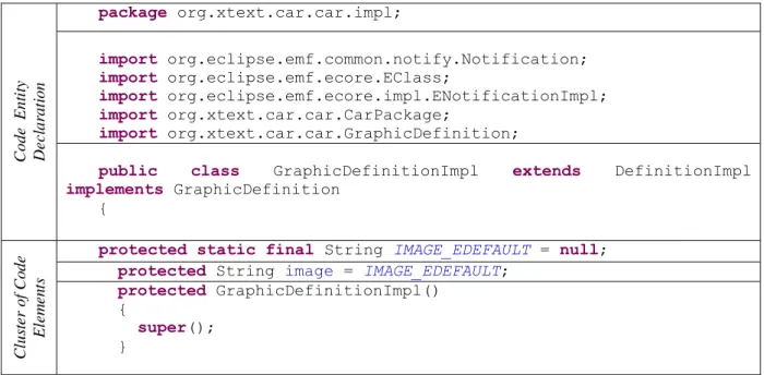
In a code body, code entity and code elements can be separated via analysis of scales. Classes, by the nature of the object oriented design, are collectives that hold the code elements. The code in Table 3.1 displays the example code body, GraphicDefinitionImp Java Class. Class declaration clause and every code part that supports the identification of the class are classified as a part of the code entities’ identification, while all statements and methods have been identified as code elements.
Depending on the programming language’s limitations and grammar design, there are different code body parts that will define the code entities and code elements. However, in this research one definition will stay true in general. A code entity, like a class in object oriented languages, is a code body that manifest though other code bodies as the main entry point to rest of its code elements, independent of the behavior of the software code. On the other hand, a code element is either a statement or an expression entry point, which can be called as a completion of an expression, but its sub elements are not independent from its behavior.
Table 3.1 Entity and Element Segmentation
Code E nt it y D e c lar at ion package org.xtext.car.car.impl; import org.eclipse.emf.common.notify.Notification; import org.eclipse.emf.ecore.EClass; import org.eclipse.emf.ecore.impl.ENotificationImpl; import org.xtext.car.car.CarPackage; import org.xtext.car.car.GraphicDefinition;
public class GraphicDefinitionImpl extends DefinitionImpl
implements GraphicDefinition { Cl us te r of Co de E le m e n ts
protected static final String IMAGE_EDEFAULT = null;
protected String image = IMAGE_EDEFAULT;
protected GraphicDefinitionImpl()
{
super();
protected EClass eStaticClass() {
return CarPackage.Literals.GRAPHIC_DEFINITION;
}
public String getImage()
{
return image;
}
public void setImage(String newImage)
{
String oldImage = image; image = newImage;
if (eNotificationRequired())
eNotify(new ENotificationImpl(this, Notification.SET, CarPackage.GRAPHIC_DEFINITION__IMAGE, oldImage, image));
}
public Object eGet(int featureID, boolean resolve, boolean
coreType) {
switch (featureID)
{
case CarPackage.GRAPHIC_DEFINITION__IMAGE: return getImage();
}
return super.eGet(featureID, resolve, coreType);
} … Code E n ti ty D e c lar at ion }// End of GraphicDefinitionImpl
For example, public class GraphicDefinitionImpl inherits from DefinitionImpl and implements the code elements of operations of GraphicDefinition interface. GraphicDefinitionImpl class’s integrity as a code entity relies on the entry definitions of the sub-code elements that it owns. On the level of structural composition for identification, it is independent to what is the behavior that relates to inner bodies of its sub entities, and it maps to its sub entries once manifested though instance declaration. However, a code element such as eGet(int featureID, boolean resolve, boolean coreType) is both identified with its entry declaration as an operation, and it is bound to the returning result from its behavior which relies to its code body parts. Hence, all code entities are can behave like code elements, but opposite is not true.
Just like types, fields and classes of object oriented design, code elements come together to create code entities, which then can create more complex structures mixing with other code elements and other code entities. Thus, by comparable complexity levels, code artifacts
divides tiers for classification. These divisions can be easily formed to already structured platform languages such as Java, C or Objective-C; however it is needed to be identified for DSLs that is constructed by the developer. Therefore, one can come to a conclusion that there is a matched level of complexity among code artifacts.
3.2 Types of Changes on Code Artifacts
At the fundamental level, code artifacts are constructed from textual structures. When we are looking for the possible changes in textual bodies of code artifacts, we can separate the code body according to level of complexity. This enables conditions which are ideal for comparison among the captured states of the matched complexity levels. This matching is the
defined relation for synchronization attempts in similarity. Two states can have different
levels of similarity, with the highest similarity level defined as “same”.
In this research, sameness means an entity or an element is completely identical between two comparable states. This means that, any change to the code body’s logical and semantic structure will break the sameness of two states of entities or elements. Thus, sameness state is less likely to pursue compared to be matching by a defined relation. Moreover, the matched level of complexity is mainly differentiated by matching of code elements and matching of code entities of the equal hierarchy.
For constructing and classifying the types of changes, [11] and [26] provided the influence for separation in type of changes of code elements and of code entities. For more of this discussion, please refer to conclusions from section 5.5.2.
In order to understand the behavior of the code body depending on the level of complexity, types of changes that can occur on the code elements and higher complexity level code entities have been studies. The findings from this analysis are then used in identification of the limitations, expected conditions and exceptional conditions on the code body parts.
3.2.1 Types of Changes in Code Elements
By their nature, code elements are in a position that further synchronization attempts to
deeper, more nested code body parts requires the support of a behavior analysis. However,
synchronization of the behavior itself is semantically challenging and rather unnecessary for synchronization attempts [13]. Behavior of a code element is constructed from statements, expressions and fields that are prone to semantically complex changes.
In this research, it is claimed that synchronizing a method’s behavior is sufficiently done without analysis of the behavior itself. The reasons are below:
(1) Statements and expressions are prone to complex semantic changes. These changes can either become successful, or they can create an inner conflict in the code element itself. However they are not interesting for analyses for outer scale impacts. [13]
(2) Moreover, code elements are identified as dependent to their code body. This reasoning lies from the fact that the return values of the code element are a result of code body that defines its expressions. However, for the code element itself, the identifier has three major features that define it. These are return type of the code element, name of the code element, and if there is any, types of parameter(s) of the code element. Such as
public void setImage(String newImage){…}
or
char c = …
At above example, public classifies the access rules for the code element, thus, it is important for Java environment. However more solid identification for the code element comes from the return type of the method void, the name of the method setImage and the parameter type of the method (String newImage). In the parameter section, general conviction indicates that parameter name itself is not valid enough to indicate the identity of the method, but rather the parameter type is of importance. In the second example, char c is able to represent the code element alone. Explanation for this classification can be found in [4] and [9].
One of the claims of this research is that, one can separate the types of changes on code elements are as follows: Different types of changes are deducted from the nature of code elements in three major ways. These are obliteration of a code element, substitution of a code element and modification of a code element. However, modification of a code element can also be separated to three different natures. These are subtraction in code element’s code body,
addition to code element’s code body and alteration of the code element’s code body.
Although modification can be separated to these three minor sub categories, if the behavioral code is not interesting for deepness of synchronization attempt, this information is not fundamental for the mechanism.
Definitions of these keywords are below.
Obliteration: Code element’s identifying clause is missing. Also, there is no found track
for an editing option for the name of the type or the method. Thus, method is considered as erased, or obliterated.
Substitution: Code element’s identifying clause is replaced by another code element.
Substitution is strongly related to Modification, with the difference of code element’s name. In obliteration, method has been totally lost; in substitution, either name or return type or
parameter features of code element have been changed.
Modification: In modification, either because of a substitution or because of a change on
the textual body of the code element, textual form has to be changed. Modification has three different versions.
Subtraction: If the code body is a block of text, then some code has been erased from
code block, without disturbing the pattern of the previous code, thus the defined relation information is kept. Hence, this enables textual integrity that can relate to previous code version.
Addition: If the code body is a block of text, then some code has been added to code
block, without disturbing the pattern of the previous code, hence enabling textual integrity that can relate to previous code version.
Alteration: Code body has been changed and it is not possible to understand whether if
previous code body and new code body was related.
An obliteration of a code element is easier to understand compared to substitution or modification. However, there is an overlap between obliteration, substitution and modification. Understanding that there was an obliteration of the code element, but not a substitution is intertwined. A both substitution and modification means a destruction of code integrity. A heuristic code identification mechanism would perceive all changed code element identifiers as obliterated. Also, substitution and modification overlaps in code change attempts that would disturb the code element identifiers. Distinctive features of these two types of changes can be easier to understand with the following scenario.
Let’s consider a situation that a developer has replaced a method in a class by another method from either another class or a written a new method. If developer wants to replace the method in object instances that calls the method too, then substitution is the desired outcome from the change operation. A substitution can also lead to a modification in cases which the modification consists of changing the identifier features. However, as deducted from [23], changing code element identifier’s features has the possibility to lead to consistency and dependency problems.
3.2.1.1 Conclusions on Changes on Code Elements
Because of the overlap between obliterations, substitutions and modifications, ability to
create equivalents plays a major role in determining the importance of deducing which of
those types of changes has occurred among code artifact states. Depending to the decisions for assessing a synchronization attempt, code elements can be separated to various forms of dept of success in synchronization to the most desired outcome. Three points are important to such
ability:
(1) Ability to deduct patterns from behavioral code body: As explained, at least in object oriented design, this ability is not interesting for most cases of synchronization attempts, but it has effects in perception of dependency among code elements and code entities that owns those code elements.
(2) Ability to follow edits on the code element identifiers: This means that, the synchronization mechanism owns and implements a design that can relate code element identifiers even after they have been changed. Thus, a change identifier can be followed though this editing history.
(3) Ability to catch developer’s intention: When there are multiple possible outcomes from the sequence of edits, it is a requirement to understand the intention of the changes. Unless there is only a single path that leads to the editing attempts, mechanisms needs to question the developer for their intentions.
3.2.2 Types of Changes in Code Entities
Code entities are composed from code elements. Code elements that are bound with code entities carry their own types of changes. On the other hand, since code entities are bound in a hierarchy and also since they are consisted of a cluster that owns identifiable separate code bodies, nature of code entities carry some changes to code elements. A code entity can be consisted of other code entities, and this may or may not change its level of complexity. Such as, a single class is a basic code entity, while a class with a nested class has still the same level of complexity but with more interchangeable code parts. However, a single Java Project is a bigger bulk of code structure that exceeds the complexity level of other two. It has a different scale and with additional attributes. Hence, it has a different matched level of complexity. Influence for these classifications is explained in section 5.5.2.
Important thing to notice is, in a synchronization attempt, unless dependency clashes occur, code elements that belong to a code entity is isolated from the effects of changes in other code elements that belong to code entity and code entities’ identifiers. However, opposite is no true. Code entities must reflect all changes that occurred on them to correspondent pairs in order to keep the level of similarity close to sameness.
Since code elements are independent from their code body’s behavior, and since they can be identified with their sub structures, they can manipulate their sub-entities. Additionally, code elements can change types that code entities inherit from code elements. This is a direct result of object oriented design pattern in structure of objects schemas [4]and also directly relates to project structures that have higher level of complexity [23].