Integrating Automatic Run-time Network Maintenance into Network Management using CORBA
HIS-IDA-EA-99-102
Anders Biederbeck a95andbi@ida.his.se Institutionen för Datavetenskap
Högskolan i Skövde, Box 408 S-541 28 Skövde, Sweden
Final year project in computer science, Spring 1999.
Submitted by Anders Biederbeck to the university of Skövde as a dissertation for the degree of B.Sc., in the Department of Computer Science.
[2001.12.18]
I certify that all material in this dissertation, which is not my own work, has been identi-fied and that no material is included for which a degree has previously been conferred upon me.
Integrating Automatic Run-time Network Maintenance into Network Management using CORBA
Anders Biederbeck a95andbi@ida.his.se
Abstract
This work address the adding, removing and upgrading of network elements in a computer network at run-time. This is already accomplished by Sun Microsystems Jini architecture, but we have investigated if it is possible to create a maintenance system that can handle this, using CORBA. We also want the manual intervention to be minimal. We have discov-ered that it is possible to create such a system, using CORBA, and that this solution also can handle upgrading a network element at run-time. This report outlines the design of this system, realizing automatic run-time network maintenance.
Table of content
1. Introduction...10
1.1 Layout of the report ...10
2. Background ...11
2.1 Distributed systems...11
2.1.1 Network Services...11
2.1.2 Network elements...11
2.1.3 Open system interconnections ...12
2.2 Distributed objects...13
2.2.1 CORBA and Java RMI...13
2.3 Network management...15
2.3.1 SNMP - Simple Network Management Protocol ...16
2.3.2 Hewlett Packard open view ...18
2.4 Defining automatic run-time maintenance ...18
2.4.1 Jini ...18
3. Problem definition ...19
3.1 Purpose...19
3.2 Automatic run-time network maintenance ...19
3.2.1 Network management services...20
3.2.2 Network element definition...21
3.3 Focus ...21
3.3.1 Representing network elements...22
3.3.2 Network maintenance: add, remove and upgrade network elements ...22
3.3.3 Communication between network and network maintenance system...24
3.3.4 Architecture ...24 4. Method ...26 4.1 Phases...26 4.1.1 Design phase...26 4.1.2 Implementetion phase...26 4.1.3 Testing phase ...26 4.2 Methods ...27 4.2.1 System design...27
4.2.2 Full system implementation ...27
4.3 Choosing method...27
5. Solution ...29
5.1 Solution overview ...29
5.1.1 System design of network maintenance ...29
5.1.2 Handling of network element representation types ...31
5.1.3 Handling of network elements in the management system ...32
5.2 Detailed solution...33
5.2.1 Detailed description of system design ...33
5.2.2 Creating a new type ...36
5.2.3 Add, remove and upgrade a network element representation ...36
5.2.4 Communication through the proxy...41
Anders Biederbeck University of Skövde
6.1 Comparison to Jini ...43
6.1.1 Jini and automatic run-time network maintenance...43
6.1.2 Jini and manual effort ...44
6.2 Network element representation...45
6.3 Network maintenance ...45
6.4 Communication between the network and the management system ...45
7. Conclusions...46
7.1 Contributions ...46
List of figures
FIGURE 1. A network element with its internal software ...9
FIGURE 2. OSI layered structure in use between two computers...9
FIGURE 3. A request being sent through the Object Request Broker. ...11
FIGURE 4. The SNMP architecture, showing a network bus with the network management system and the managed device connected to it.14 FIGURE 5. Comparison between OSI, TCP/IP and SNMP ...14
FIGURE 6. Logical overview of the system architecture ...16
FIGURE 7. The difference between a network element representation and the software resident on the hardware18 FIGURE 8. System design overview. Yellow parts are handled in this report. ...26
FIGURE 9. System hierachy ...27
FIGURE 10. Software representation of Hardware ...28
FIGURE 11. State synchronization ...30
FIGURE 12. Maintenance unit interface design showing the IdType repository. ...31
FIGURE 13. The state patterns according to Gamma et.al ...32
FIGURE 14. The object lifecycle interface...34
FIGURE 15. The operations of the CORBA lifecycle interface...34
FIGURE 16. System design of a representation, including the config, and state interface. 35 FIGURE 17. The states of a remove action ...36
FIGURE 18. State diagram, only covering the States of the upgrade action ...37
FIGURE 19. Design of the Proxy module ...39
FIGURE 20. Use case view...47
FIGURE 21. Object model...48
FIGURE 22. Create new type ...48
FIGURE 23. Add new network element ...49
FIGURE 24. Add new instance...50
FIGURE 25. Find existing type...50
FIGURE 26. Add existing network element ...51
FIGURE 27. Create instance ...51
FIGURE 28. Remove network element - early alert ...52
FIGURE 29. Remove network element - late alert ...52
FIGURE 30. Remove instance ...53
FIGURE 31. Upgrade network element ...53
FIGURE 32. State synchronization ...54
FIGURE 33. Get configuration data ...54
FIGURE 34. Configure network element ...55
FIGURE 36. State diagram ...56
Anders Biederbeck Introduction University of Skövde
1. Introduction
Today, many computers are interconnected in networks. The individual network element, such as a router, may perform a specific task or deliver a service, e.g. routing, that can be used by any other network element. This solution is a result of the desire to be able to per-form different tasks on a network without having to implement every service in every net-work element that needs that service. This report investigates how we may add, remove and upgrade a network element in an operational network. This ability is referred to as automatic run-time network maintenance. We want this task to be as automated as possi-ble, i.e., the manual intervention must be set to a minimum.
Sun Microsystems has released the Jini architecture that may be used to accomplish this, but we want to investigate the possibilities, and advantages or disadvantages of a solution using the Common Object Request Broker (CORBA) developed by Object Management Group (OMG). To accomplish the sharing of services, distributed objects are introduced. A distributed object can use the operations and services of other objects across a heteroge-neous network. CORBA realises a standard, set by OMG that allow objects to interact over the boundaries of platform, e.g. Windows NT or Macintosh. The CORBA approach does not only provide a platform independent solution, but also a language independent solution.
This work shows that it is possible to realise automatic run-time network maintenance, using CORBA. Furthermore, the solution makes it possible to upgrade a network element at run-time. Like the Jini approach, the manual intervention involved in the CORBA approach is set to a minimum if the network element manufacturers also provide the nec-essary software to represent the network element. Otherwise, this software must be cre-ated, and a method to do this is presented in this report.
1.1 Layout of the report
The layout of the remainder of this report is as follows:
Chapter 2 explains the background to the area of network maintenance and to the problem we address in particular. Chapter 3 defines the actual problems that we have investigated and chapter 5 explains our methods of choice. Chapter 5 gives the solution to the problems presented in chapter 3. In chapter 6, we discuss the results achieved from the solution pre-sented in chapter 5, and we compare our solution to Sun Microsystems Jini architecture. In chapter 7 and we present our contribution to the field of network management. This chap-ter also discusses future work in this area.
2. Background
In this chapter, information related to the problem is introduced and discussed.
2.1 Distributed systems
A distributed system consists of several computers doing something together (Schroeder, 1995). Further, a distributed system has some primary characteristics such as multiple computers and interconnections between them. Each computer consists of a processor, local memory, possibly some stable storage like disks, and interconnections to connect it to the environment. A distributed system can be seen as an abstraction, providing the users with services, and thereby fulfilling its goal. If the services are not delivered or delivered in a faulty matter, the system is not consistent to its specification. A heterogeneous distrib-uted system consists of multiple computer platforms and/or languages. A platform is the combination of the underlying hardware and the operating system (Kollars, 1999), e.g., Macintosh or a Sun SPARCstation. The applications running on a platform can be imple-mented in different languages, such as Java or C. A distributed system may be a client/ serversystem. The client requests services provided by a server. The server may also request services from another server, making it a client to that server. The computers that are connected to a network are part of the set of network elements, and they provide the distributed system with services.
2.1.1 Network Services
User(s) of the system perceive the system as the functionality it provides (Laprie, 1994), i.e., a human user does not care about how a page is spooled before it is printed, the user does only want the printed page to appear at the printer. Another example is when a remote call is carried out between two objects. The initiator of the call does not care how the recipient handles the request, it only cares about the reply. Laprie defines a user as another system, physical or human, which interacts with the former system. Such a service can be the ability to print a document on a high-resolution printer or send mail. A network element or a set of network elements delivers the services of a network.
2.1.2 Network elements
A network element can be viewed as a managed device (Cisco, 1999). A network element can be a server, a printer, a router, or any other device that contributes to the network behavior. A network element consists of hardware and software installed by the manufac-turer of the hardware (see figure 1). The internal software manages the hardware, e.g., the operating system in a server.
Anders Biederbeck Background University of Skövde
FIGURE 1. A network element with its internal software
Network elements communicate using a protocol that may be based on open system inter-connections.
2.1.3 Open system interconnections
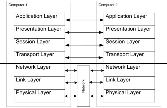
Open system interconnections (OSI) as a standard set by International Standard Organisa-tion (ISO) with the purpose of allowing computers to communicate with one another in an open way (Halsall, 1996). OSI consists of a layered structure, where every layer provides a defined set of services to the layer immediately above it. It does so by using the services provided by the layer immediately below it (see figure 2). Every layer has a well-defined function and communicates with its peer layer in the remote system.
FIGURE 2. OSI layered structure in use between two computers. In short, the functions of these layers are:
• The application layer provides the user interface.
Network element instance
Software resident on network element Hardware resident on network element Computer 1 Application Layer Physical Layer Link Layer Network Layer Transport Layer Session Layer Presentation Layer Computer 2 Application Layer Physical Layer Link Layer Network Layer Transport Layer Session Layer Presentation Layer Net w ork
• The presentation layer handles the syntax between two communication application
pro-cesses.
• The session layer sets up the communication channel between two application
pro-cesses. It organises and synchronises the communication.
• The transport layer acts as an interface between the higher application oriented layers
and the lower networkdependent layers.
• The network layer establishes and clears a network wide connection between two
trans-port layers.
• The link layer provides the network layer with reliable information transfer facility. • The physical layer handles the electronic interface between the user equipment.
We will use the OSI-model as a foundation for comparison in order to reveal where our solution appear in the OSI-model.
2.2 Distributed objects
A distributed object is an object that communicates with other objects that may or may not share the same address space or processor (Fingar and Stikeleather, 1999). When one cli-ent communicates with a server, the clicli-ent does not need to know the location of the server, e.g. the client and the server may not reside on the same machine. This is referred to as location transparency. Another aspect of transparency is that it makes it easier for the programmer, who does not have to care about how the objects are implemented. This is referred to as representation transparency (Pope, 1998). All the programmer needs to know is the interface of the object he or she will access.
Fingar and Stikeleather (1999) explain that communication between distributed objects consists of messages carried by some sort of interface. This interface may be based on TCP/IP, SNMP, IIOP or any other available network protocol. These messages represent requests for information or services. The object assumes the role of client or server. When a client invokes a method call on a server, possibly located on another node, the client does not know whether the server resides on the same machine or not, or how the server will handle the request. This location, and representation transparency can be achieved by using CORBA, Java RMI, or any other architecture supporting distributed objects.
2.2.1 CORBA and Java RMI
Common object request broker architecture (CORBA) and Java remote method invocation (RMI) are two different solutions to the problem of interaction between distributed objects in a heterogeneous environment. OMG defines CORBA as the answer to the need for interoperability among rapidly proliferating number of hardware and software products available today (OMG, 1998c). They also describe the Object Request Broker (ORB) as the middleware that establishes the client/server relationships between objects (see figure 3). OMG also states that an ORB acts as a software bus between the client and the server and facilitates communication between objects (OMG, 1997). The ORB translates the
Anders Biederbeck Background University of Skövde
request of the clients so that it can be transported over the network, sends it to the server, and retranslates the request back to a form that the object can understand at the server end.
FIGURE 3. A request being sent through the Object Request Broker.
There are several similarities between CORBA and Java RMI, such as the use of stubs and skeletons, and the locating of a remote object given an object reference. A stub resides at the client end and state what operations (services) the clients may invoke on the server. The skeleton resides at the server object, e.g. the object implementation, and provides interfaces to each service exported by the server. In CORBA, this approach makes it possi-ble to handle heterogeneous environments and different implementation languages of the objects. In Java RMI, both the server and the client must be implemented using Java. The ability to find a server object is fundamental in both solutions. Both CORBA and Java RMI realises a repository of current objects, where a client can locate a server object. When a server object is located, the client can use its services. This makes it important to register a newly created server object in the repository, making its services visible to the clients in the network.
Sun Microsystems states that Java RMI allows you to write distributed objects using Java (Sun Microsystems, 1998). Java RMI does not use an ORB, but transports the request over the network as bit-strings, e.g. using TCP/IP. Java interprets bit-strings, turning it into objects or requests at its destination. Since Java RMI is an extension of Java, RMI benefits from the same advantages as Java. Java RMI is object-oriented and allows objects and their states to be passed over the network. This is called passing object by value and it makes it possible to move an object to a remote location and execute it locally to the con-sumer of its services. Java RMI is also secure in the sense that it protects the system from unauthorised access by remote code (objects passed by value) that is being executed on the system. CORBA has today no such feature as passing objects by value but OMG tries to solve this in the new version of CORBA (Vinosky, 1998). RMI also realises distributed garbage collecting (i.e., obsolete objects are removed from the system) and parallel com-puting (Sun Microsystems, 1998). The drawbacks of Java RMI are that RMI do only work between objects implemented in Java, also RMI do not support asynchronous method calls as CORBA does, resulting in that a request to another object locks the requesting object
Client Object Implementation
Request
until it receives a response. Finally, RMI does not make it possible for a object to dynami-cally discover what methods are available on other objects and use them, without having a prior knowledge of them (Duplancic & Lindberg, 1998). This is possible in CORBA and it is referenced to as dynamic invocation. CORBA and Java RMI can be used to realise net-work management systems.
2.3 Network management
Network management is defined as the ability to manage a network and the services the network provides to the users. Network management is the adjustment of system state by a human manager (Schroeder, 1994). A systems state is defined as a snapshot of its configu-ration at a given time. He means that management is when human judgement is needed to maintain a network. The services a network provides are what the users see (see section 2.1.1). Also, a network must scale well, i.e. the network must be able to handle increased load without being saturated. In this work, increased load primary originates from nodes added to the network. Network management includes the following tasks:
I Network maintenance
Network maintenance is how we maintain the network. To maintain a network is to keep it up and running, while keeping it consistent. We may also want to make alterations, e.g. add new hardware or remove hardware. We do this to maintain or expand the services of the network. To maintain a network, we must posses control over the network elements. This control must be based on the information provided by the network services below. The vision is to have all this automated.
II Ability to reconfigure existing network elements
To reconfigure a network element is change the behavior of the network element. It may still provides the same services but it does so in a different way, i.e. a server may be reconfigured to provide a new service, or a router may have to be reconfig-ured to adapt to a new node in the network.
III Ability to monitor the network, regarding performance, security and fault handling. Performances are a measure of the load, or strain the network experiences. This is accomplished by watching the traffic progressing through the network. By saving this information, prognoses of future loads can be estimated.
Security handles data alterations. Data may not be altered in an unauthorised fash-ion, but it still has to be accessible to the users (Laprie, 1994).
Fault handling comprises the ability to handle faults when they occur, preferably without any degradation of the network performance.
Anders Biederbeck Background University of Skövde
2.3.1 SNMP - Simple Network Management Protocol
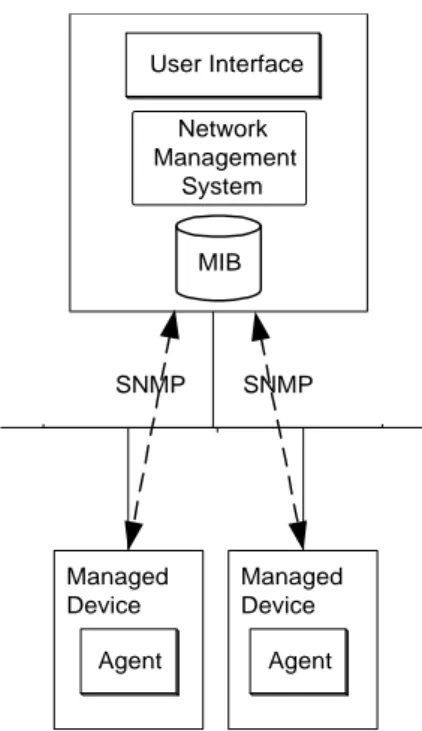
Simple Network Management Protocol (SNMP) is a protocol developed to manage a work. The managed network elements must have an agent resident that represents the net-work element. Management is located at a central computer in the netnet-work, called a network management station (see figure 4). The management is performed by sending variables with requests over the network (Case, 1990). SNMP offers four different interac-tions between network management stainterac-tions and the managed device:
• Reads: To monitor managed devices a network management stations read variables
maintained by a network elemento
• Writes: To manage monitored network elements a network management station writes
variables stored within the managed network elements.
• Traversal Operations: Network Management System use traversal operations to
deter-mine which variables a managed device supports and to sequentially gather information from variable tables (such as IP routing tables) in managed devices. Traps: Managed devices use traps to asynchronously report certain events to the network management systems.
• Traps: Managed devices use traps to asynchronously report certain events to the
net-work management systems.
SNMP uses a virtual information store to keep track of its managed devices. This store is called Management Information Base (MIB), and it can be seen as a database containing the managed objects.
FIGURE 4. The SNMP architecture, showing a network bus with the network management system and the managed device connected to it.
SNMP is based on User Datagram Protocol (UDP). This approach makes the communica-tion unreliable since UDP packages can be lost (Stallings, 1996). SNMP has no mecha-nism to check this, thus it is up to the application that uses SNMP to take steps to retransmit a lost package. SNMP is an Internet protocol and it is, today, not compatible to OSI. It is built upon the structure of TCP/IP (see figure 5).
FIGURE 5. Comparison between OSI, TCP/IP and SNMP
Managed Device Managed Device Agent Agent User Interface Network Management System MIB SNMP SNMP Application layer Physical layer Link layer Network layer Transport layer Session layer
Presentation layer Process
Network Access Internet Host-To-Host SNMP Network Access IP UDP OSI TCP/IP
Anders Biederbeck Background University of Skövde
2.3.2 Hewlett Packard open view
HP Open View is a solution that is based on SNMP (Hewlett Packard, 1998). A HP Open-View solution makes it possible for a single administrator to monitor a large network from a single location. This manager uses polling to check the status of the agents. The man-aged device, using the traps available in SNMP, can set the polling frequency. HP Open-View is a powerful solution but it does not fully support automatic network maintenance as will be specified in the section below, because hardware must be manually configured into the management system.
2.4 Defining automatic run-time maintenance
Automatic run-time maintenance refers to the ability to change a network at run-time. Our approach to this problem is to add, remove and upgrade network elements under the run-time control of a distributed or central management system. To be able to connect a wide range of network elements to the network, without changing the management system accordingly, our solution hides the hardware details from the management system. This is accomplished by representing hardware to the management system as software. We can now manage the software representation of the hardware, leaving the details of the hard-ware to its softhard-ware representation. Today, there are some solutions to the automated maintenance problem.
2.4.1 Jini
A Jini system is a Java technology centred, distributed system (Sun Microsystems, 1999). The result is that Jini enable sharing of a service to the entire network. In this view, a serv-ice is an entity that can be used by a person, a program, or another servserv-ice. This definition agrees with our definition of a service (see section 2.1.1). The overall goal of Jini is to cre-ate a network where the topology may change at runtime and where network elements and services can reside, move, disappear or appear without manual configuration. Jini assumes that each device has some memory and processing power. However, devices without pro-cessing power or memory may be connected to a Jini system, provided that these devices are controlled by another piece of hardware and/or software.
3. Problem definition
This chapter describes the problem in more detail.
3.1 Purpose
The purpose of this work is to investigate the possibilities of automating the handling of hardware in a network, making it a simple task. Ultimately, the network technician should only have to plug in the hardware in the network, turn the hardware on, and the hardware will then automatically become part of the network. We want to investigate if it is possible to add, remove, and upgrade hardware in a network at run-time, and propagating changes to the management system at run-time.
3.2 Automatic run-time network maintenance
Automatic run-time network maintenance means that the management system can handle additions, removals, and upgrading of network elements without unnecessary manual intervention. To accomplish this, we assume a system architecture (see figure 6) where the network management system is part of the network.
FIGURE 6. Logical overview of the system architecture The architecture comprise four parts:
• System - This is the overall view of the system where all the parts presented below
belong. This view includes the users of the network, the network and the network man-agement system (see below). When we talk about the system, we talk about this view.
• Network - The network is part of the system and it comprises the physical network
ele-ments of the network. All the hardware and cables belong here. This is also the part that our management system is managing.
System
Network
Network management system
Network maintenance system
Anders Biederbeck Problem definition University of Skövde
• Network management system - This is the existing management system in a system.
The network management system is pure software, and its sole purpose is to manage the network. This work does not define this management system but we assume that there is such a system present in the system.
• Network maintenance system - This is the part we will emphasise in this report. The
maintenance system helps the existing management system to maintain the network elements. Figure 6 shows a logical view where the maintenance system is a part of the management system. This view is how the personnel managing the network perceive the maintenance system. Our view is that the maintenance system is an independent part that provides the management system with a maintenance service.
We do not want the management system to communicate directly to the network elements, because this will force us to adapt the management system to the network elements present at the moment. That kind of system does not support network maintenance as defined above. What we want to do is to hide the specific protocol of the network element. To enable this we must assume that the specification of a network element is represented by software, where every software representation represents one network element. This assumption is made because our emphasis is on the software representation of network elements. When a change occurs in the network element that influences the management services, its software representation must reflect these changes. This is to make the
man-agement system aware of the changes made to the network element.0
3.2.1 Network management services
Network services are, as described in subsection 2.1.1, how users see the network. The management services this report covers are alarm handling, performance checking and reconfiguration services. These services are central in network management since they provide information about a network upon which a network can be managed. They also represent the three directions that data may flow in the system; input from network ele-ment when an alarm is raised; output to network eleele-ment when it is reconfigured; and both directions when checking the performance.
Alarm handling is how the system gets notified, and reacts to a failure of a network ele-ment. We assume that network element failures are detected and reported, either by the network element itself or by the management system.
Performance checking is when the performance of the network is evaluated. Making snap-shots of the system is a way to do this. A snapshot is a view of the predefined parameters in the system at an exact moment in time. Snapshots usually occur at regular intervals, giving an overview of the system performance. By computing the data retrieved from these snapshots, a trend can be generated. By defining thresholds, the degrade of perfor-mance can be handled as an alarm (see above).
Reconfigure a network element means that the network element is changed. If a new ser-vice is added to the network, and an existing hardware deser-vice is designated to handle it, then the device must be reconfigured to meet the new demands. This is to keep the system consistent as stated in section 2.1.
3.2.2 Network element definition
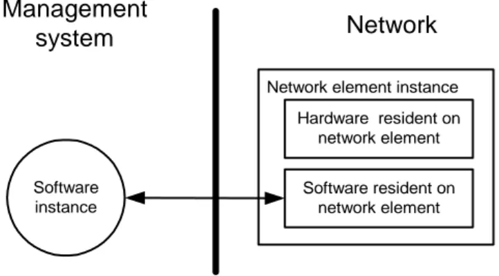
As stated in subsection 2.1.2, a network element is a computer connected to the system, delivering some services. In this project, a network element is the hardware. We also assume that every network element instance connected to the network has a unique iden-tity, memory, processing capabilities, and an interface that connects it to the network. These assumptions are based on Schroeders (Schroeder, 1995) definition of a distributed system in section 2.1. A unique identity is essential since the management system must be able to know who is who, and who does what. For example, if an alarm is raised, the alarming network element provides its identity along with the alarm. If this identity were not unique, the receiver of the alarm may not be able to tell the source of the alarm, and it may not be able to respond. To be able to create a software instance representing a net-work element, the management system must know how the netnet-work element communi-cates. This instance must be able to communicate with the manufacturer software resident on the network element. To do this, it must know what interface the network element uses. Figure 7 show that the network element comprises the hardware and its software resident on the network element. Separate between the software resident on the network element, which is installed by the manufacturer of the hardware, and the software resident in the management system, which is created by the management system to represent the network element, when the network element is installed in the network. This project emphasise on the network management software and the general design of the interface between the software representation and the network element.
FIGURE 7. The difference between a network element representation and the software resident on the hardware
3.3 Focus
This final year project focuses on the network maintenance system (see figure 6). It is assumed that when a network element is connected to the network, it announce its pres-ence to the management system, providing information about itself. Out primary problem is to realize the maintanence system, wich will break down into three minor problems that
Software instance
Network Management
system
Network element instance
Software resident on network element Hardware resident on
Anders Biederbeck Problem definition University of Skövde
will solve our primary problem. Firstly, the network elements must be represented in a way that makes it possible for the management system to manage the network element. It is also important that the network element can fulfil its purpose in the network through the representation. Secondly, the representations must be able to be added, deleted and upgraded at run-time. This is the actual network maintenance as described in subsection 3.2. Thirdly, the network representation and the management system must be able to com-municate, regardless of what protocol the network element uses to communicate.
3.3.1 Representing network elements
As stated above, we will represent network elements with software, fulfilling the demand of network element hiding. This makes it very important that these representations are cor-rect, in the sense that they can behave in correspondence to the actual network element. Our problem lies in this fact because we also want to represent a wide range of different network elements with a minimum of effort. For example, to add a new router to the net-work must be similar to adding a new server, even though the two demand different repre-sentations. We must have a specification upon which a representation can be based. We can consider the specification as a blueprint of a general network element. In this report, a type is an interface specification and an implementation for a network element. All types comprise the same specification, but the network element implementation differs.
3.3.2 Network maintenance: add, remove and upgrade network elements
We want it to be an easy task to add, remove, and upgrade a network element. As stated above, we want a minimum of manual intervention when performing these tasks. The add scenarios comprise the following problems:
• The network element must announce its presence to the maintenance unit. • The maintenance unit must find the type matching the network element.
• The maintenance unit must create a representation according to the type, at the right
location on the network.
The problems stated above will be solved in subsection 4.2.3. We are satisfied with saying that the network element must announce its presence to the maintenance unit. We will also specify this announcement protocol, but leave out the protocol details. We only know the information needed to create a new representation. We must also define a specification that will work, as stated in subsection 3.3.1 above. This specification is used as a founda-tion when we create a new type that will create a new representafounda-tion. Since we use distrib-uted objects, it is not essential where the representation will reside, it will represent its network element regardless of its location. We may want to group similar representations in one location, to make logical groups of representations, but this is not essential and we leave it to the system implementer to decide how this will be handled. When we have solved these problems, we must continue with the problem associated with the removal of a network element. The problem is:
• We must separate between a deliberate removal of a network element, and a failure of
This problem occurs if the network element looses the connection to its representation. The representation will report a network element failure since it cannot communicate with the network element any longer. If it, in fact, is a deliberate removal of the network ele-ment that has occurred, then the representation must be removed, and an alarm raised by the representation serves no purpose. When these problems have been solved, we can add and remove a network element, but we must also be able to upgrade a network element. To upgrade a network element means that we upgrade the network element to provide extended services to the system. The upgrade action present us to the following problems:
• As in the removal of network element, we must differ between an upgrade of network
element, a removal of a network element and, a network element failure.
• We must replace the old representation with a new representation that matches the
upgraded network element.
• We must provide the management system with a type that it can use to create a new
rep-resentation.
• We must provide the new representation with the current states and the state history of
the old representation.
• We do not want to loose any information while we synchronise the old and the new
rep-resentation. During the synchronisation, the representation is inaccessible, but we still do not want to miss the data transferred between the network element and the represen-tation during this period (e.g. the network element raises an alarm while the representa-tions are being synchronised, this alarm must be the first issue for the new representation to deal with).
• We must remove the old representation.
• We must establish communication between the new representation and the network
ele-ment.
Some of the problems stated here have already been explained earlier in this subsection. We will now relate them to the current problems of this subsection.
When we upgrade a network element, we usually disconnect it. We must make sure that this does not result in a removal of the representation, because we need the old representa-tion in the synchronisarepresenta-tion phase explained below. We cannot upgrade an existing repre-sentation to match an upgraded network element. This is because the reprerepre-sentation is a compiled object and it cannot be upgraded with less then a recompilation. So we must replace the old representation with a new representation that already have been compiled. To create this new representation, we must find a type that matches the network element, and if no such type is found, we must create one. The new representation must exist com-piled somewhere on the network, ready to represent a specific network element. If it does not exist, we must compile it externally to the management system, and make it available to the management system, at run-time.
The only thing that the new representation lacks is the current state, and the state history of the old representation. We must somehow transfer this data to the new representation. This
Anders Biederbeck Problem definition University of Skövde
is referred to as state synchronisation. This state synchronisation phase presents new prob-lems:
• How do we prevent a failure during the synchronisation phase?
• What happens to the data transferred during synchronisation, when the representation is
unable to handle this data?
The first problem addresses the fault tolerance of the system. We assume that there can only be one fault at the time, and a new fault will not occur before the first one is handled. This assumption makes it easier for us to focus on how to solve these problems. The state synchronisation phase must be able to guarantee some kind of safety, i.e. at the end of the synchronisation phase we must have a representation that can represent the network ment. The second problem stated previously addresses the availability of network ele-ments. We do not want the network element to be unavailable during synchronisation, i.e. changes in the network element must be kept and integrated in the new representation once it connects to the network element.
The deletion of the old representation is the same problem as the delete problem explained earlier. As in that problem, we must differ between a failure of network element communi-cation, and a deliberate removal of this communication link. When the synchronisation phase is done, and the old representation is obsolete, it must release its communication link to the network element and be deleted. The management system must know that there is a new current representation representing the network element. Also, the new represen-tation must establish a communication link to the network element it represents. These are all critical actions that must be solved in a safe way.
3.3.3 Communication between network and network maintenance system
The maintenance system that we design in this project is aimed at being used regardless of the protocol used in the network elements. We know that the software participants in the management system can communicate with each other, using the same protocol, but we do not know the protocol used by the network elements we manage. We assume that the net-work elements do not use the same protocol as the software participants. We must make sure that the management system can be used in a multi-protocol network environment. For example, we have a network consisting of two network elements, one using Token ring to communicate, and the other using SNMP, based on TCP/IP. In this scenario, we have two representations that are managed, but we cannot assume that the management system can communicate directly to any of them. The problem we must solve is how to intercommunicate between the management system and a network element.
3.3.4 Architecture
As we have seen in section 3.3.3, we do not know at designtime what network elements we will handle, in fact, this report tries to design a system that can handle most networ-kelements. The issue here is not the actual network element, but the network element rep-resentation. We want to design a system that can communicate between software objects that represent a network element in a correct manner. In subsection 2.4.1 we came across
the Jini architecture. This architecture is designed to handle object detection and inter object communication at runtime, but the Jini architecure is built upon Java, which we know only can communicate with objects written in Java. Since we do not want to limit our network element software to be written in Java, we are forced to turn to other architec-tures. Our other alternative is CORBA. As stated in subsection 2.2.1, CORBA supports interoperability among rapidly proliferating number of hardware and software products available today (OMG, 1998c). This feature makes CORBA suitable for our purposes. We may design and implement a maintenance system that can handle network element repre-sentations from different vendors, or write our own reprerepre-sentations, using a language of our choice.
Anders Biederbeck Method University of Skövde
4. Method
This chapter describes the different approaches that may be used when solving the prob-lem stated in chapter 3. We will also define what approach we will use, and why we will use it. This final year project is a software development project and, as such, we must evaluate the analysis, design, implementation and testing phases. These phases are all part of a software development project and they will be adressed in this chapter. It must be noted that the analysis phase is already finshed and can be viewed in chapter 3. When we know the problems we must solve, we also know what we are up against.
The chioces we have to make in this section is how we will conduct the project
4.1 Phases
This section will describe the different phases we mentioned above. We will not specify all the details, but give an overwiev of the different phases.
We start with the design phase.
4.1.1 Design phase
Pressman states (Pressman, 1982) that the design phase is the first step in the development phase for any engineered product or system, and he continues by saying that the designer´s goal is to produce a model or representation of an entity that will later be built. During the design phase we create a blueprint of the system to be built. This blueprint is an abstract wiev of the system and will contribute with an overview that are directly linked to the implementation phase.
4.1.2 Implementetion phase
The implementation phase is the phase where we create the system, based on the design we made earlier. If we have made an correct design, the implementation phase will be a static phase that merely carry out the instructions founded in the design phase, using some programming language. The goal of the implementation phase is to create a program or a system that compiles. It is to early to say that it will work, this is left to the testing phase.
4.1.3 Testing phase
It is during the testing phase that we verify that the system built in the implementatoin phase works. The testing phase may be conducted in many different ways, depending on what kind of system we are creating, and it’s goal is to find errors in the system. A testcase that does not result in errors found is a bad testcase. This is because there are always errors in a fairly complex system, and if we did not find any errors, it indicates that we conducted the test in a faulty way. Some errors are to be considered to be minor, and does not lead to debugging, while others are major, and forces us back to the design or implementation phase.
4.2 Methods
This section will describe how we may use the phases mentioned above to create the maintenance system.
4.2.1 System design
In subsection 4.1.1, we made it clear that there are no other way to develope software than to execute the design phase. This is because this phase outlines the system to be built, and if we choose not to design the system, and starts the implementation directly, we will not be able to reach our goal. Implementing a complex system without a blueprint results in a poor system.
When we design our maintenance system, we use the requirement extracded in chapter 3, and identify the roles, classes and states of our system. We will use Unified Modeling Lan-guage (UML) to do this. The more accurate this phase is executed, the easier the imple-mentation and testing phase will be.
4.2.2 Full system implementation
The design phase is the only phase that we can conduct as a singel action. The result of that would be a design of the maintenance system. If we chooce to implement the system, we must also conduct the testing phase. Our implementation choices are C++ or Java. Both these languages are quite similar, i.e they are both object oriented, but they design different low-level system behavoiur. We discribed in subsection 2.2.1 how Java RMI works and howJava makes use of bytestreams to transport data and object across a hetero-geniou network. C++ does not have this feature and because of this, C++ is the better choice. If we are to really test our system, we must make it work in C++, because many of the representations we must handle may very well be written using C++. If we choose to conduct the design and the implementation phase, the testing phase must follow. This is because we othervise do not know if we built what we have designed. The testing phase is also our verification of the design. The testscenario we are facing comprise a network of no less then two nodes. One node for the maintenance system and one node to be attached and detecded by the maintenance system, or we simulate the scenario using memorys-paces on a single computer. Either way, we try to create an as realistic testcase as possible, using those recourses we can muster. Our goal is to verify the system design.
4.3 Choosing method
As stated above, we have two methods to consider; system design or full system imple-mentation. If we want to verify that the system we built are consistent to the requirements, we must chose full system implementation. This is the only way to reach to the testing phase, and there by, get the verification we want. There are yet the time aspect to consider. If we are to apply both design, implemetation and testing in the time allocated to us, we must minimize all three phases. This means that we make a quick design, that very proba-bly will prove to be faulty, implement this design and run out first testcase. we will then be
Anders Biederbeck Method University of Skövde
forced back to the designphase to correct the faults, reimplement and test again. This is a realistic scenario that we may be able to realize, but will the resulting system verify our requirements? If we instead chose the system design, we have time to make a design that makes it easy to implement. I believe that the system design method is the one method that contributes to the sphere of computer science, since it will show if it is possible to realize the maintenance system, even without the implementation and testing phases.
5. Solution
This chapter will present our solution to the automatic run-time network maintenance problem presented in chapter 3 above. We will present a solution that solves the adding, upgrading, and removing of network elements in a distributed system, and how the legacy problem is handled. It is important to notice that it is the handling of network elements that results in actions in the management system.
5.1 Solution overview
This section presents the main issues in our solution, presenting an overview of the system design. We use CORBA in our management system to accomplish location and represen-tation transparency.
5.1.1 System design of network maintenance
This subsection will describe the system design that we have extracted from the problems stated in chapter 3.3, and present the participants of the network management system. Fig-ure 8 shows the modules of the system design.
FIGURE 8. System design overview. Yellow parts are handled in this report.
The network management system comprises a network management module that manages the system (see section 2.3). This module may also comprise a graphical user interface that makes it possible for the network managing personnel to manage the network. The network management system communicates with the network maintenance units and the network element representations. There may be several maintenance units, controlling a specified group of network element representations (see figure 9). A network element rep-resentation represents a specific network element in the network. This reprep-resentation
com-Network management system Network maintenance Unit Network element representation Network
element proxy Network element
Logical connection Physical connection
Anders Biederbeck Solution University of Skövde
prises a configuration object and a state object. The configuration object is used when a user wants to configure a network element, and the state object comprises the state of the representation. The state object makes it possible to change the representation behaviour, depending on the current state of the representation. This is achieved using state patterns (Gamma et. al, 1994). The state pattern approach also makes it easy to introduce changes in the network element representation. More about this in subsection 4.2.1.
The communication between a network element and a network element representation is passed through a network element proxy. This is because we do not want to prepare the network element with a CORBA ORB or a CORBA client and server. The network ele-ment proxy converts the communication between CORBA and the network eleele-ment proto-col.
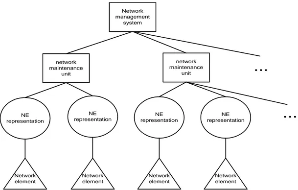
The modules of the system developed are ordered in a hierarchical fashion (see figure 9). Note that we have omitted the proxy in figure 9. This is because there is one proxy assigned to every network element protocol used in the system, and we leave it up to the implementer of the network management system to decide how this is handled in reality. One possibility is that every maintenance unit handles representations representing net-work element assigned to a specific protocol, and thus references one netnet-work element proxy.
FIGURE 9. System hierachy
Every module in the system design performs a specific task and handles the data assigned to that task. For example, the network element representation maintains the network ele-ment specific data and, if the manageele-ment system wants to alter this data, it has to use the operations specified in the network element representation interface. The task of the
net-Network management system network maintenance unit network maintenance unit NE representation NE representation NE representation NE representation
...
...
Network element Network element Network element Network elementwork management system is to manage the system as stated above. The management sys-tem communicates directly with the network element representations, but it must rely on the maintenance unit to locate the network element representations. This is one task of the maintenance unit. The maintenance unit also creates, destroys, and initialises upgrade of network element representations, on behalf of the management system. The network ele-ment representations main task is to represent one network eleele-ment (see figure 10). To represent a network element means that the representation is perceived as the actual net-work element by the management system, and thus capable to act as the actual netnet-work element. The representation hides the specifics protocol about the network element from the management system and the maintenance unit. Seen from the view of the network ele-ment, the representation is the receiver of the management specific output from the net-work element. Figure 10 shows a further developed view of the architecture of the management system, where every representation is clearly linked to one network element, and the maintenance unit controls every network element representation.
FIGURE 10. Software representation of Hardware
All modules in the management system comprise objects that are abstract data types, designed to maintain its specific data. For example, a representation is an abstract data type within which the specific data of a network element is maintained. This feature is achieved using object-oriented design and implementation. We must also be capable to handle distributed objects since the location of a network element, or its representation, is not known at compile time. Network elements or their representation may also appear, dis-appear and move as a result of maintenance activity in the network.
5.1.2 Handling of network element representation types
When we add or upgrade a network element, we use types to describe the characteristics of the network element. A type comprises a specification and an implementation. The type
Network
Network management system
Network maintenance unit
Network element representation:
Router Hardware Instance:Router
Hardware Instance:Server Network element representation: Server
Anders Biederbeck Solution University of Skövde
specification describes a generic interface that all network elements must support. The type implementation realises this specification, and adds a network element specific inter-face that have to be provided to make the representation accurate. The implementation has to be realised by a person, and provided to the network by the means of floppy, CD, or it may be possible to get the type implementation from the network element manufacturers Internet site. The network element specific interface may be omitted if the generic inter-face represents the network element correctly. The implementation of the type must, ini-tially, always be provided to the system. The implementation decides how the operations and attributes of the interface will be implemented.
The types available to the system are stored in a repository handled by the maintenance unit. When a new network element is added, the maintenance unit consults the repository to see if the type already is present in the system, and, if it is, the maintenance unit uses that type to create a new representation.
5.1.3 Handling of network elements in the management system
When a network element is added to the network, it first has to obtain a distinct low-level network address. This may be provided by a DHCP-server. Once the network element has obtained this, it has to locate a proxy that support the protocol used by the network ele-ment. This can be done by broadcasting its presence, or by performing a look-up. The proxy module knows where to find the maintenance unit and when the network element have made it self known to the proxy, i.e. its characteristics is passed on to the mainte-nance unit. The network element can now communicate to the maintemainte-nance unit of the management system, and it may identify itself using its unique id. We must also create the representation that will represent the network element to the management system, and this will be covered below.
When a network element is removed from the system, its representation must also be removed. The reference to the network element type still exists in the repository, in case that the network element or a similar network element will be added at a later point. We must somehow differ between the removal of a network element, and the failure of a net-work element. Introducing explicit notification of a remove action solves this.
To upgrade a network element comprises an upgrade that affects the management system, i.e. an upgrade of network element that changes the management systems handling of the network element. To do this, the representation that represents the network element to the management system must be replaced with a new representation. We must also differ between a removal of network element and an upgrade of the same. It is possible that we must disconnect the network element from the network when we perform the upgrade, and the representation of the network element must not be removed until the network element is reconnected, and a new software instance is up and running. This is because the new software instance that will represent the upgraded network element must synchronise with the old software instance before it can represent the network element (see figure 11). All these steps have to be done without loosing any data.
FIGURE 11. State synchronization
This action is encapsulated in a transaction that either succeeds or fails. If a failure occurs, the transaction rolls back and no changes have been made to the representations. If the transaction succeeds, the new representation establishes a logical connection to the net-work element, through the proxy module, and the old representation is removed. As in the case of removal of a network element, we use explicit notification to differ between an upgrade of network representation, and a failure of the same.
5.2 Detailed solution
This section will describe the solutions presented above in a detailed manner.
5.2.1 Detailed description of system design
This subsection will focus on the details that we omitted in subsection 4.1.1. The detailed design of the maintenance unit is presented in appendix A. This project is focused on the
State S1 Existing -State S1´ 1 State S2 Existing -State S2´ New -State I 2 State S2 Existing -State S2´ New -State S2´ Syncronize states 3 State S2 Existing -State S2´ New -State S2´ State S3 New -State S3´ 5 6
Anders Biederbeck Solution University of Skövde
realisation of the maintenance system, and the details of the management system will be omitted in this report.
The design of the maintenance unit is showed in figure 12. The maintenance unit main-tains the IdType repository that keeps track of the type-network element Id relations. This is where the maintenance unit turns to find a type matching a network element about to be added.
FIGURE 12. Maintenance unit interface design showing the IdType repository.
The maintenance unit module includes two packages, the software_instance and the protocol_proxy. The software_instance is the network element represen-tation and the protocol_proxy is the translator between the represenrepresen-tation and the network element.
The representation design comprises a configuration object and a state object. The config-uration object is adapted to maintain the configconfig-uration data for each representation, and must be set by a user. The configuration object in its most simple form is an object that defines the basic parameters in all network elements. We may inherit from this basic con-fig object to create concon-figuration objects that fit the representation we will add, e.g. a router. This results in a hierarchical structure where the specific network element is repre-sented and, if needed, it may be further developed to make and model of network element. The creation of a configuration object is a manual labour, but as stated above, we have developed a method to make this work easy. Note that a configuration object may apply to several similar representations, but the similar representations must maintain one instance of the configuration object each. Two representations cannot share one instance because a user may alter the configuration data at a specific representation at run-time, and we do not want this alteration to reflect any other representation but the one we intend to manip-ulate.
The state object maintained by each representation has three main purposes:
Hardw are_ID H ard ware_ty pe
net work _ a dd res s i nst an c eID S oftw are_ty pe
IdTy peM apping get_m appin g() s et_m appin g() < < Interfac e> >
+ m _H ard ware_ID + m _IdTy peM apping M ai nte nanc e_un it
m ode : c har*
get_i ns tan ce(K ey : i ns tan ceID) : Ins tanc e A dd_ m e ( addre ss : ne twor k_ad dres s , Hw ID : H ardware_ID) provide_ty pe( ty pe : S oftw ar e_ty p e)
NE _unava ilable( ID : ins tanc e ID) upgraded(ID : ins tanc eID ) s et _upgr ade( ID : ins tanc e ID ) Rem oveM e( Se lf : Ins tanc eID)
< < Interfac e> >
1..1 + m _Hardw are_ty pe
1..1
+ m _M aintenanc e_u nit 1 ..1 + m _n etwork _addres s
1 ..1
+ m _M aintenanc e_unit 1..1
+ m_ inst anc eID 1..1 + m _M aintenanc e_unit 1 ..1 + m _S oftwa re _ty pe 1 ..1 + m _M aintenanc e_unit 1..1 1..1 + m _M aintenanc e_unit
+ m _IdTy peM appin g 1..1 1..1 H ardw are_ID 1..1 + m _M aintenanc e_unit + m _H ard ware_ID 1..1 In s tanc e
(from Logic al V iew)
P rotoc ol prox y (from Log ic al V iew)
Ty p edef
1..1 1..1
• To reflect the states of the network element.
• To make the state transfer at state synchronisation easier.
• To inform the maintenance unit of the current state of the representation, e.g. running,
remove, upgrade, synchronise or unconnected.
The first purpose means that the current state of the network element is not maintained in the representation, but is transferred to the state object. The second purpose state that the occurrence of a state object makes it possible for us to synchronise states by allowing the new representation to receive the old representation’s state object. An alternative would be to make several calls, receiving one state value per call. The number of calls would then be the number of state values. In our solution, we get one call containing all state values and we minimise the effort involved in the synchronisation phase. The third purpose is the solution to the explicit notification problem when removing or upgrading a representation. When a network element is to be deleted or upgraded, a user informs the management sys-tem about the changes to come, and the state object is forced to change its state from
runningto remove or upgrade (see figure 12). This is accomplished using state pat-terns (Gamma et. al, 1994). When the representation changes state, it also prepare it self for the changes to come. We will explain these properties further in subsection 4.2.3. The state patterns approach allows an object to alter its behaviour when its internal state changes. The object will appear to change class (Gamma et.al. 1994). Figure 13 shows an overview of the state pattern structure, as developed by Gamma et.al.
FIGURE 13. The state patterns according to Gamma et.al
The client interacts with the Context class, and the State class maintains the states of the Context class. The State class defines an interface for encapsulating the behaviour associ-ated with a particular state of context. The subclasses of the state class implements behav-iour associated with a state of context, i.e. the handle() operation in concreteStateA may be implemented differently then the same operation in concreteStateB. This is because the actions taken may differ between the states of the context. This makes it pos-sible for us to change behaviour depending on what state the context has assumed. How we use the state pattern is explained in subsection 4.2.3.
An object design in UML is provided in appendix A.
c onc r eteS t ateA
Han dle() c o nc ret eS tat eB Handle() S t ate Han dle() Contex t reques t() s tate st ate- > Handle ()
Anders Biederbeck Solution University of Skövde
5.2.2 Creating a new type
As stated above, a type is used to create a representation, and it comprises a specification and an implementation. It is the user who decides what will happen when the management system calls a predefined operation in the representation interface. He or she does this by implementing the specification. The default interface specification must be implemented because the operations defined in the default interface must exist for our management sys-tem to work. Also, the design of the representation serves as a framework for the imple-menter where he or she may have to alter the code to the operations to implement the specification. To make the representation represent the network element in a correct man-ner, the user may add extra operations or attributes to the default interface. As stated in subsection 4.2.1 above, we use state patterns to handle the representation in the manage-ment system.
5.2.3 Add, remove and upgrade a network element representation
The central part of the maintenance system is the maintenance unit. This module handles adding, deleting, and upgrading of the network element representation. This is the main task of the maintenance unit. It has to keep track of the protocol proxies present in the sys-tem, because a newly added network element announces its presence through this proxy (see subsection 4.1.3). The maintenance unit also maintains the type repository, and con-sults it when a new network element is added to the network. The network management system must use the maintenance unit to locate a specific network representation. When a new network element is added and a type is located, the maintenance unit locates a factory that can create a network element representation.
The problem of creating, and destroying network element representations is solved by the use of CORBA lifecycle service. Pope (1998) states that an objects’ lifecycle runs from its creation until it is deleted or destroyed. An objects’ lifecycle is represented by a lifecycle interface. An object dedicated to the creation of objects handles the creation of an object. These are called factories. A factory is the only way for a client to create an object in CORBA, and the maintenance unit is a client when it creates a new representation object. A factory can only create an object in the area where it reside, e.g. a computer connected to the network, or a certain memory area in a computer. This is referred to as a factories scope. The LifeCycleService provide us with two interfaces that helps us to create repre-sentation objects:
• Factory finder • Generic factory
To create a new representation, the maintenance unit may use the factory finder interface to locate a factory object that resides on the node where the new representation will be cre-ated. That is, we know where the representation must be created, and we check if there is a factory whose scope covers the location where the new representation must reside. The found factory object must know how to instantiate a representation of the specified type. A factory is only an object that can create other objects of a specified type, such as another factory or a representation. The client (maintenance unit) issues a create request on the
returned factory reference, and is returned a reference to the created object. Figure 14 shows the two interfaces included in the CORBA Lifecycle service, and the operations that can be invoked on these interfaces. The factory finder and the generic factory handle the creation of objects. The “supports” operation of the generic factory is an operation that returns true if the factory supports creation of the requested representation.
FIGURE 14. The object lifecycle interface.
When we want to remove a representation, we use the CORBA life cycle service as well. The maintenance unit, using the CORBA lifecycle services, accomplishes the removal of a representation. The CORBA lifecycle services provide us with a lifecycle interface (see figure 15) that help us to copy, move and remove an instance. We will focus on the remove action. The other two may be used but they will not be regarded in this project.
FIGURE 15. The operations of the CORBA lifecycle interface
To understand how we handle the remove and upgrade actions of the network element, we must first explain our design of the state object, using the state pattern (Gamma et.al 1994). Figure 16 shows our specification of a representation.
find_factorys create_object GenericFactory FactoryFinder supports remove move copy LifeCycleObject