Dynamics and electronics of a manually
chargeable quadcopter for steady-state
flight
Bachelor Thesis in Aeronautics
Mälardalen University
Academy of Innovation, Design and Engineering Authors: Ioannis Kantsaporidis & Sadeq Al-Attar Date: 2017-10-12
ii
Preface
We would like to thank our examiner Håkan Forsberg for his encouragement of our ideas and guidance in writing this report.
iii
Abstract
The objective of this thesis is to investigate how the onboard battery of a quadcopter can be charged through manual rotation of its motors, while understanding the resulting aerodynamical forces acting on the rotors during hover, as well as considering the changes in thrust capabilities when the electronic and structural design are altered.
A theoretical approach using the momentum theory will present a general understanding of rotor performance whilst describing the correlation between rotor parameters, thrust and mechanical power. Furthermore, the idea of using the motors as generators are put under study to investigate their electrical output and utilize them to recharge the battery. This is done using the counter electromotive force equation, and a sequence of other equations that will present numerical data of actual manual work converted into electrical power. Resulting in the required time to manually recharge the quadcopter subsequently sustaining hover flight for three minutes.
It is concluded in this report that manual recharging of the battery using the motors as generators is possible, as well as maintaining its flying ability in case of added weight. Although not deemed practical in commercial use, it is a new methodology with the intention to develop a sustainable quadcopter further expanding its practical applications in both aviation industry and human aid.
iv
Table of Contents
Preface ...ii Abstract ... iii Table of Contents ... iv Nomenclature ... v 1. Introduction ...1 1.1 Problem formulation ...2 2. Background ...32.1 Basic Newtonian laws ...3
2.2 Momentum theory for hover ...3
2.3 Magnetic field ...4
2.4 Electric charge and electromotive force ...4
2.5 General concepts of motors and generators ...4
2.6 Charging ...5
3. Method ...6
3.1 Momentum theory for hover ...6
3.2 Power ...7
3.3 Electronics ...8
3.4 Back-emf and current production of a motor ...8
3.5 Electronic circuitry ... 10
3.5.1 Connections ... 10
3.5.3 Ultra-low voltage converter ... 10
3.6 Electric power ... 11
3.7 Choice of build materials ... 11
3.8 Choice of battery ... 12 4. Results ... 13 5. Discussion ... 15 6. Conclusion ... 16 7. Future work ... 17 References ... 18 Appendices ... 23
v
Nomenclature
V Voltage [𝑉𝑉] R Resistance [𝛺𝛺] I Current [𝐴𝐴] m Mass [𝑘𝑘𝑘𝑘] l Length [m] w Width [m] Millimeters [𝑚𝑚𝑚𝑚] Tesla [T] 𝜌𝜌 Density of air [𝑘𝑘𝑘𝑘/𝑚𝑚3] g Gravitational constant [𝑚𝑚/𝑠𝑠2] 𝑉𝑉𝑒𝑒 Back-emf [𝑉𝑉] ω Angular velocity [𝑟𝑟𝑟𝑟𝑟𝑟/𝑠𝑠]AC Alternating current [A]
DC Direct current [A]
𝐾𝐾𝑒𝑒 Back-emf constant [𝑚𝑚𝑚𝑚/𝑅𝑅𝑅𝑅𝑅𝑅]
𝑚𝑚̇ Mass flow per unite time [𝑘𝑘𝑘𝑘/𝑠𝑠]
N Number of turns of a copper-wire
A Area of one of the loops inside a motor [𝑚𝑚2]
B Strength of magnetic field [𝑇𝑇/𝑚𝑚2]
f Frequency [𝐻𝐻𝐻𝐻] W Watt [𝑊𝑊] Watt-hour [𝑊𝑊ℎ] p Pressure [𝑅𝑅𝑟𝑟] v Velocity [𝑚𝑚/𝑠𝑠] A Area [𝑚𝑚2] G Gauss T Period [s]
K Sensor sensitivity [mv/Gauss]
Index
VTOL Vertical take-off and landing
W Weight
T Thrust
Min Minutes
RPM Revolutions per minute
rps Revolutions per second
CAD Computer aided design
PMDC Permanent magnet direct current motor
1
1. Introduction
Development regarding unmanned VTOL vehicles is moving at a fast rate and is considered to have a major impact on the aviation industry. Applications adapted for emergency situations in regards to signaling and communications are also being further improved [50, 51].
This report aims to develop an existing quadcopter enabling it to be charged manually through its own motors, achieving vertical take-off and landing, sustaining three minutes of hover flight and eventually performing a task e.g. distress light signaling. In theory it is a completely automated sequence with no required input control by the user, thereby eliminating maneuverability issues during emergency situations. However, no further explanation regarding automation takes place in the study, thus assuming an automated vertical motion A to B and B to A. This procedure is repeated after the quadcopter is safely back on ground, enabling the user to perform a manual recharge of the battery on the spot and launching the quadcopter to repeat the task.
The quadcopter model, “Reely Twister Quadcopter RtF”, is dimensioned 150 × 150 mm and consists of four symmetrically placed rotors on a cross-shaped frame, where each rotor is placed in pairs in order to counteract the resulting moments created by corresponding pair. The rotors are in turn respectively connected to four motors that feed of a 3.7 V battery. Current battery recharging time is 55 min through an electricity outlet enabling the quadcopter to maintain flight for about eight minutes.
The motors on a quadcopter are used for rotating the rotors but could also be used as electricity generators. Therefore, could a quadcopter’s battery be recharged by its own motors through rotating a hand crank-gear? A solution may be found by constructing a quadcopter with four small gears, each one of them attached to a motor, an external hand crank-gear that is fitted between the motors/gears and a certain change in the electronic circuitry. Rotating the hand crank-gear will rotate the motors and thus generate electricity.
After constructing a prototype in CAD seen in appendix A, a theoretical approach using the momentum theory is used to determine the aerodynamical forces acting on the quadcopter, as well as showing the correlation between power and thrust. The thrust is calculated by splitting the airflow within a streamtube into sections with different areas, where the mass flow is equal across the whole tube, divided only by an infinitesimal thin rotor disc. Consequently, having an insight in how much added weight the quadcopter is able to handle without intercepting the mechanical power needed to attain hover flight.
Manual charging takes advantage of high gear ratio to rotate the motors and generate electricity, which is directed to the battery. Additionally, parallel connections between the motors are made to increase the current output thus increasing the rate of charge, as well as using an ultra-low voltage amplifier to exceed the battery voltage achieving steady charging. Calculations of power consumption and motor electricity production, answers the question of how many minutes needed for manual charging that offer a sustained hover flight for three minutes.
The study results show that the battery can be manually charged, where the amount of time needed to reach a full charge is about 11 hours, thus three minutes of flight requires approximately 4 hours of manual charging compared to the 55 minutes via an electricity outlet. While aerodynamical studies show that no more than six extra grams can be added to the quadcopter in able to withhold its flying ability.
2
1.1 Problem formulation
The objectives of this thesis are as followed:
How/if the onboard battery of a quadcopter can be charged through manual rotation of its motors.
Investigate the amount of charging time needed to achieve three minutes of flight.
Understanding the resulting aerodynamical forces acting on the rotors, and determining the induced velocity along with the required rotor power to sustain hover.
Investigate if thrust and power capabilities are sufficient if the electronic and structural designs are altered.
3
2. Background
2.1 Basic Newtonian laws
During rotation of a rotor both the direction and velocity of the surrounding air is changed inducing an equal and opposite reaction on the rotor which generates thrust T. Newton’s Second
Law defines such an event as change in momentum with change in time [53]. 𝐹𝐹 = 𝑚𝑚(𝑣𝑣1−𝑣𝑣0)
(𝑡𝑡1−𝑡𝑡0) (1.0)
Which is then simplified to:
𝐹𝐹 = 𝑚𝑚𝑟𝑟 (1.1)
The weight of the quadcopter is the gravitational force acting on the mass of the object which is derived from Newton’s law of universal gravitation [52]:
𝑊𝑊 = 𝑚𝑚𝑘𝑘 (1.2)
Thrust must consequently equal the weight in order to sustain hover capability, or greater for an accelerated upward motion.
2.2 Momentum theory for hover
Momentum theory is a one-dimensional mathematical approach using the laws of conservation mass, momentum and energy [53, 54], and is a fundamental step in understanding rotor performance. Early development by W.J.M. Rankine (1865), Alfred George Greenhill (1888) and R.E. Froude (1889) views a rotor as an infinitely thin actuator disc surrounded by accelerating air within a streamtube and correlates between thrust and induced velocity. Certain conditions are assumed [8]:
Homogeneous, inviscid and incompressible fluid flow. No frictional drag or energy losses.
Uniform flow and uniform forces over the disc area. All fluid rotation is neglected within the streamtube. Infinitely thin rotor disc area.
Furthermore, applying Bernoulli’s equation on the streamtube while limiting calculations upstream and downstream on both sides of the rotor disc, a pressure difference acting on the rotor is given resulting in a force T, acting in the opposite direction of the air flow. As seen in figure 1, air goes through the inflow constrained by the “walls” of the streamtube where 𝑝𝑝0 and 𝑚𝑚0 is the
freestream atmospheric air pressure and velocity. Approaching the rotor disc upstream, as seen in figure 1, static pressure 𝑝𝑝1 and dynamic air pressure 12𝜌𝜌𝑚𝑚2 is lower whereas pressure 𝑝𝑝2 ahead
of the disc is higher resulting in a pressure difference 𝛥𝛥𝑝𝑝 = (𝑝𝑝2− 𝑝𝑝1). This in turn leads to the
thrust equation where the pressure difference acts along the disc area which is the first step in determining the induced velocity and finally the power:
𝑇𝑇 = 𝐴𝐴(𝑝𝑝2− 𝑝𝑝1) (1.3)
Towards the end of the streamtube 𝑝𝑝3 is reduced back to freestream pressure, exit air velocity 𝑚𝑚3
is however greater than the freestream air due to the rotor doing work on the airflow. The mass flow across the entire streamtube is constant and is deduced through the continuity equation [53, 54, 59]:
𝑚𝑚̇0= 𝑚𝑚̇1= 𝑚𝑚̇2= 𝑚𝑚̇3
4
2.3 Magnetic field
The magnetic field is a magnetic force that is emitted from certain materials. The field is created as a result from the current of charges that is generated due to the activity of electrons that float around the nucleus in the atoms of these specific materials. This field can be used to induce current in other conductive materials like copper, or semi conductive materials, like silicon. For instance, the magnetic field of earth is between 25 to 65 µT [2, 4].
Materials that can become magnets are called Ferromagnets. These have the right properties in their atoms, and they exist in a variety in nature. Some of them are found as ready magnets in nature due to their exposition to natural electric charges like lightning bolts. When a current of charges pass through the material, the atoms align in a specific way and make them magnetic. However, some of the ferromagnetic materials lose their magnetic fields after the current is gone and other materials like cobalt and iron have the ability to keep their atoms aligned to become permanent magnets [5].
The magnetic flux is a term used to represent the quantity of the magnetic field, and the change of a magnetic flux of one weber per second inside one turn of a conductive wire produces one volt of an electromotive force [3].
2.4 Electric charge and electromotive force
The electric charge is generated from the movement of electrons in a conductive material, and this movement occurs when there is a change of a near magnetic flux. Faraday's law on electromagnetic induction states that the change could be in the strength of the magnetic flux or just by moving the magnet near to or away from the conductive material. Furthermore, the magnitude of those induced charges increases proportionally with the change of the magnetic flux [7]. The amount of work done per unit charge by a source in transporting a charge from one of its terminals to the other is called the electromotive force of the source. The flood of these charges is called current [6].
Emf occurs in two types, AC, where charges fluctuate back and forth like a sine or a cosine wave, and DC, where charges travels only forward [8].
An example on current and voltage of electric charges is water flowing through a pipe. The water flow has a volume, which represent the electric current, whereas the pressure of the water represents the electric voltage [9].
2.5 General concepts of motors and generators
The general concept of motors is that a number of turns of a copper wire rotates freely between at least two permanent magnets. A coil is made of multiple turns of a conductive wire. When electricity passes through a coil, it creates a magnetic field and when the direction of the electricity is reversed through exchanging terminals of connection, the magnetic field also changes polarity. One of the ways to pass electricity as well as to continuously exchange connections to coil terminals is attaching brushes made of carbon. The brushes touch the two terminals of the coil in
5
a way that every time a voltage source is connected to them the copper wire creates a magnetic field that is opposite to the magnetic pole that is facing it. In that way the coil rotates in a direction away from the opposing pole, creating a force called torque. Once the coil reaches the second pole, the brushes touch different spots of the coil so that it rotates further away from the opposing second magnetic pole, repeatedly rotating away from the opposing poles leading to continuous rotation and creating a motor.
Therefore, a motor is a machine that converts electrical energy into mechanical energy. Moreover, motors are now made in many variants due to the demand for higher speeds and torques, which is accomplished by adding more turns of copper-wire, greater area of wire and/or stronger magnets. Additionally, turns of wires are generally wrapped around a metallic shaft called armature, which also works as a heatsink for the coils. However recently developed micro motors without armatures called coreless, have become prominent for their efficiency and light weight [10].
The used motor in this study is a brushed type, meaning it uses brushes to transfer electricity. Whereas another type of a dc motor called brushless dc motor, uses no brushes and is constructed so that the magnets rotate freely around the coils instead of the other way. Included inside the motor is a micro circuit that is programmed to change polarity of the coils in order to keep pushing away the magnets, rotating around in one direction [11].
A generator on the other hand is a machine that converts mechanical energy into electrical energy and is made of precisely the same components as of a motor. However, it is through rotating the coils between the magnets that a current is induced in the coils. Thus, the current flows out through the carbon brushes that touch the coil-terminals. According to Faraday’s law, this happens due to the continuous interception of coils with the magnetic field lines. The way coils are wrapped around the armature plays a big role in how many of these coil-turns are cutting the magnetic lines. Additionally, determining whether the output electricity is AC or DC depends on the internal design of the generator, meaning the arrangement of the brushes in how they receive the current [7, 12].
Several elements are considered in calculating a generator’s output, voltage, torque and RPM [24]: Length of the conductors inside the motor and their cross-sectional area.
Number of turns or number of conductors. Strength of magnetic field.
Number of magnetic poles.
Armature design and how the coils are wounded around it.
The equation of back-emf uses angular velocity and the back-emf constant to calculate the average voltage produced [16, 20, 21]:
𝑉𝑉𝑒𝑒 = 𝜔𝜔 × 𝐾𝐾𝑒𝑒 (1.5)
2.6 Charging
Charging batteries occur when the power source terminals i.e. the positive and the negative are connected to the battery terminals in a manner of positive to positive and negative to negative. Current then starts flowing, and the battery in its complex structure saves it efficiently. However, in order to start the charging, the voltage of the source must equal or exceed the battery's voltage. Whereas, the amount of current decides how much time the battery requires to be fully charged. Nevertheless, batteries are limited to how much current intake they are able to withstand. Too high current heats up batteries and might lead to overcharging and overheating, which could be hazardous [25].
The PMDC generators are power sources, and power sources can be connected in parallel. When the quadcopter's motors are connected in parallel, the output current is equal to the sum of all motors’ currents and the voltage is equal to one motor's emf [26, 29, 30, 31]:
𝑉𝑉𝑜𝑜𝑜𝑜𝑡𝑡𝑜𝑜𝑜𝑜𝑡𝑡= 𝑉𝑉𝑥𝑥+ 𝑉𝑉𝑥𝑥+ 𝑉𝑉𝑥𝑥… = 𝑉𝑉𝑥𝑥 (1.6)
6
3. Method
The notion is to find and compare the power outputs between a rotor and a motor. In order to maintain hover, a rotor requires a certain amount of mechanical power to reach its necessary angular velocity, where the mechanical power is distributed through the motor shaft. Therefore, the initial step is to find the exit velocity of the air in the streamtube, and then compare the required rotor power to the output mechanical power of a motor. In order to obtain the generated emf of a motor, two methods are to be used:
Back-emf equation Multimeter measurement
The values from each method are then compared to eachother to verify if the calculated values are plausible, while also determining which method to base this project on. From there on, the current will be calculated using Ohm's law, thereafter use the gear ratio’s result to calculate the final voltage and current outputs. However, for charging to even start, the final voltage output will need to be amplified through an ultra-low voltage step up converter, as well as choosing to connect the motors in parallel in order to achieve high current to optimize charging. Finally, it is intended to compute battery power and motor power consumption to further inspect the quadcopter's specifications.
3.1 Momentum theory for hover
Implementing the continuity equation into the Bernoulli equation and dividing the streamtube into an upstream and downstream section ∆𝑝𝑝 is determined. Whereas
𝑝𝑝0= 𝑝𝑝3 and 𝑚𝑚1= 𝑚𝑚2 = 𝑚𝑚𝑟𝑟 [55, 56, 59].
Upstream: 𝑝𝑝0+12𝜌𝜌𝑚𝑚02= 𝑝𝑝1+12𝜌𝜌𝑚𝑚12 (1.7)
Downstream: 𝑝𝑝2+12𝜌𝜌𝑚𝑚22= 𝑝𝑝3+12𝜌𝜌𝑚𝑚32 (1.8)
Continuing and denoting the pressure difference:
∆𝑝𝑝 = 𝑝𝑝2− 𝑝𝑝1=12𝜌𝜌𝑚𝑚32−12𝜌𝜌𝑚𝑚02
∆𝑝𝑝 =12𝜌𝜌(𝑚𝑚32− 𝑚𝑚02) (1.9)
Using equations (1.3), (1.9) an expression for T is derived [60]:
𝑇𝑇 = 𝐴𝐴∆𝑝𝑝 = 𝐴𝐴12𝜌𝜌(𝑚𝑚32− 𝑚𝑚02) (2.0)
7
The velocity across the rotor, 𝑚𝑚𝑟𝑟 can be described as the sum of the freestream and induced
velocity, where the induced velocity 𝑚𝑚𝑖𝑖, is generated by an increase in rotational energy through
the rotor disc. It can also be expressed as the mean velocity of the freestream and slipstream air [55, 60]: 𝑚𝑚𝑟𝑟 = 𝑚𝑚0+ 𝑚𝑚𝑖𝑖 (2.1) and 𝑚𝑚𝑟𝑟 =𝑣𝑣0+𝑣𝑣2 3 (2.2) Equaling (2.1), (2.2) 𝑚𝑚𝑖𝑖 is expressed: 𝑚𝑚𝑖𝑖=𝑣𝑣3−𝑣𝑣2 0 (2.3)
In hover mode 𝑚𝑚0= 0, showing that the aircraft is stationary in the air. If the aircraft would initiate
a climb then 𝑚𝑚0≠ 0.
𝑚𝑚3= 2𝑚𝑚𝑖𝑖 (2.4)
From (2.4) it is deducted that the induced velocity at the end of the streamtube is double its original value at the rotor, or differently the induced velocity is half its original value at the end of the streamtube. Understanding that 𝐹𝐹 = 𝑚𝑚𝑟𝑟 can also be written as 𝐹𝐹 = 𝑚𝑚̇𝑚𝑚 [61] it is convenient to express the thrust in those terms, taking advantage of the fact that the momentum flow is constant across the entire streamtube. The thrust can then be expressed:
𝑇𝑇 = 𝑚𝑚̇𝑚𝑚𝑟𝑟= 𝜌𝜌𝐴𝐴𝑚𝑚𝑖𝑖(𝑚𝑚0+ 𝑚𝑚𝑖𝑖) (2.5)
However, combining (2.4), (2.5) and considering that 𝑚𝑚0 = 0 during hover, the thrust equation is
expressed as:
𝑇𝑇 = 2𝜌𝜌𝐴𝐴𝑚𝑚𝑖𝑖2= 2𝑚𝑚̇𝑚𝑚𝑖𝑖 (2.6)
Where the induced velocity is denoted:
𝑚𝑚𝑖𝑖= �2𝜌𝜌𝜌𝜌𝑇𝑇 (2.7)
As noted in (1.2) the weight of the quadcopter must equal the thrust in order to maintain hover, therefore (2.7) is expressed:
𝑚𝑚𝑖𝑖= �2𝜌𝜌𝜌𝜌𝑊𝑊 (2.8)
3.2 Power
When the induced velocity is determined it is used to find the induced power required to propel the surrounding air in hover flight where according to (2.6), 𝑚𝑚0= 0. The difference in work in
respect to time between point 0 and point 3 in the streamtube, figure 2, is the required power [55, 62]:
𝑅𝑅 =𝑟𝑟𝑊𝑊𝑟𝑟𝑑𝑑 =∆𝑚𝑚𝑚𝑚2𝑟𝑟𝑑𝑑 2
𝑅𝑅 =2𝑟𝑟𝑑𝑑𝑚𝑚 (𝑚𝑚𝑜𝑜𝑜𝑜𝑡𝑡2− 𝑚𝑚𝑖𝑖𝑖𝑖2) =2𝑟𝑟𝑑𝑑𝑚𝑚 (𝑚𝑚32− 𝑚𝑚02)
⇒ 𝑅𝑅 =2𝑟𝑟𝑑𝑑𝑚𝑚 ((𝑚𝑚0+ 2𝑚𝑚𝑖𝑖)2− (𝑚𝑚0)2)
8
As seen in (2.6) the above equation can then be rewritten:
⇒ 𝑅𝑅 = 𝑇𝑇𝑚𝑚𝑖𝑖 (2.9)
3.3 Electronics
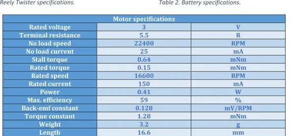
The quadcopter under development is called ''Reely Twister Drone RtF'' [44]. Table 1, table 2 and table 3 preview the specifications of the quadcopter as well as its battery and motor. In order to obtain the generated emf of a motor, two methods are to be used:
Back-emf equation, 𝑉𝑉𝑒𝑒 = 𝜔𝜔 × 𝐾𝐾𝑒𝑒 Multimeter measurement
The motor is a coreless motor, meaning that it does not have an armature and the multimeter measurement for its voltage output is approximately 0.0043 𝑉𝑉×𝑟𝑟𝑟𝑟𝑚𝑚/𝑠𝑠 . This output is measured by attaching a hand-crank to the motor shaft and rotating the hand-crank one revolution per second while the motor terminals are connected to the multimeter.
Quadcopterspecifications Flight duration 8 minutes
Propeller diameter 5 cm
Total weight 32 grams
Charging time 55 minutes Table 1. Reely Twister specifications.
3.4 Back-emf and current production of a motor
Once a source emf runs a motor, coils in the motor also generate emf called back-emf, which resists the emf source and is proportional to it. Back-emf is the generated voltage of a motor and is generated because of coils cutting the magnetic field lines, therefore motors are also generators [18]. Back-emf is equal to the emf that is generated from a motor when rotated by an external force, which is also called motional emf in a generator.
Equation (1.5) of back-emf equals angular velocity times the back-emf constant [16, 20, 21]: 𝑉𝑉𝑒𝑒 = 𝜔𝜔 × 𝐾𝐾𝑒𝑒
Batteryspecifications Voltage 3.7 V
Capacity 300 mAh
Discharge rate 25 Coulombs
Weight 9 Grams Table 2. Battery specifications.
Motor specifications Rated voltage 3 V Terminal resistance 5.5 R No load speed 22400 RPM No load current 25 mA Stall torque 0.64 mNm Rated torque 0.15 mNm Rated speed 16600 RPM Rated current 150 mA Power 0.41 W Max. efficiency 59 % Back-emf constant 0.128 mV/RPM Torque constant 1.28 mNm Weight 3.2 g Length 16.6 mm
9
Back-emf constant is motor rated voltage divided by its rated RPM [16]:
𝐾𝐾𝑒𝑒 =𝑅𝑅𝑅𝑅𝑅𝑅𝑉𝑉 (3.0)
The back-emf constant is used from table 3:
𝐾𝐾𝑒𝑒 = 1.28 × 10⁻⁴ 𝑉𝑉/𝑅𝑅𝑅𝑅𝑅𝑅 (3.1)
𝑉𝑉𝑒𝑒 = 𝜔𝜔 × 𝐾𝐾𝑒𝑒 = 60 × (1.28 × 10−4) = 0.0076758 𝑉𝑉 ≈ 0.0077 𝑉𝑉 (3.2)
It is noticed that the output of equation (3.2) is different from the multimeter reading. Equation (3.2) is therefore considered to be the most accurate theoretical result for the emf. However, it is intended to use the value of the multimeter measurement. Voltage that is produced by four motors per second in case of parallel connection, according to multimeter measurement:
𝐸𝐸𝑚𝑚𝐸𝐸 = 0.0043 𝑉𝑉
The crank-gear has 440 teeth and the small gear on the motor shaft each has 12 teeth [32]: 𝐺𝐺𝑟𝑟𝑟𝑟𝑟𝑟 𝑅𝑅𝑟𝑟𝑑𝑑𝑅𝑅𝑅𝑅 = 𝑅𝑅𝑜𝑜𝑑𝑑/𝑅𝑅𝑖𝑖 × 𝑅𝑅𝑜𝑜𝑑𝑑/𝑅𝑅𝑖𝑖 × 𝑅𝑅𝑜𝑜𝑑𝑑/𝑅𝑅𝑖𝑖 . .× . .× ..
Gear ratio for one motor:
12 440 = 1 36.7 ≈ 1 36
This means that one crank revolution gives 36 motor-shaft revolutions per second.
When considering the natural human-rotating speed by manual testing, the conclusion is that a human is capable of rotating the hand-crank comfortably making two revolutions per second, therefore:
Motor-shaft-revolutions per second by the hand crank: 36 × 2 = 72 𝑟𝑟𝑝𝑝𝑠𝑠 Emf output from one motor by hand crank:
72 𝑟𝑟𝑝𝑝𝑠𝑠 × 0.0043 𝑉𝑉 = 0.310 𝑉𝑉
As seen in (1.6) in a parallel connection the voltage remains unaffected, therefore the Emf output for all the motors equals:
𝐸𝐸𝑚𝑚𝐸𝐸𝑜𝑜𝑜𝑜𝑡𝑡𝑜𝑜𝑜𝑜𝑡𝑡 = 0.310 𝑉𝑉
In order to find the motor resistance, to consequently calculate the produced current, a practical approach is used connecting the motor to a current supply of around 3A and simultaneously measuring the voltage and the current flowing to the motor while holding the motor-shaft to prevent rotation. When holding the motor-shaft in different positions, the voltage and current values experience fractional variations thus using the mean value as the nominal value is preferred [63].
𝑅𝑅𝑟𝑟𝑟𝑟𝑖𝑖 𝑚𝑚𝑟𝑟𝑣𝑣𝑜𝑜𝑟𝑟 𝑅𝑅𝐸𝐸 𝑚𝑚𝑅𝑅𝑣𝑣𝑑𝑑𝑟𝑟𝑘𝑘𝑟𝑟 =2.29+2.28+2.27+2.264 = 2.275 𝑉𝑉 𝑅𝑅𝑟𝑟𝑟𝑟𝑖𝑖 𝑚𝑚𝑟𝑟𝑣𝑣𝑜𝑜𝑟𝑟 𝑅𝑅𝐸𝐸 𝑐𝑐𝑜𝑜𝑟𝑟𝑟𝑟𝑟𝑟𝑖𝑖𝑑𝑑 =0.66+0.65+0.66+0.664 = 0.6575 𝐴𝐴
10
Thus, Ohm’s law is used to calculate the resistance using the mean values: 𝑅𝑅 =𝑉𝑉𝐼𝐼 =0.65752.275 = 3.46 𝑅𝑅ℎ𝑚𝑚
Consequently, as the motor voltage production and the resistance between its electrical terminals are known, it is possible to calculate the current produced by a motor:
𝐼𝐼 =𝑉𝑉𝑅𝑅=0.00433.46 = 0.00124 𝐴𝐴 (3.3)
Current that is produced by four motors by hand crank, in case of parallel connecting: 4 × 0.00124 × 72 𝑟𝑟𝑝𝑝𝑠𝑠 ≈ 358 𝑚𝑚𝐴𝐴
3.5 Electronic circuitry
3.5.1 Connections
The terminals of the motors must have their own wire connections directly to the battery aside from the wires connected to the quadcopter's circuit. The wires to the battery will have a toggle switch, which should be put in an off-position when flying the copter in order to prevent short-circuit. Also, a forward diode will be added to these connections to allow current flow in one direction, from motors to battery in case of recharging [28].
Generally, when connecting big size industrial generators in parallel, voltage regulators and systems are installed together with the generators to manage the total output voltages when generators are differing in outputs from each other [27]. However in this study, the total voltage from the motors combination will be steady because of all the motors being subjected to the same speed. And if any differences in voltages occur, they will be in very small fractions and will thus be neglected.
The advantage of blocking-diodes will be used again in the parallel connections so as to control current to flow only to batteries and not to other motors [28]. Wire connections between the motors and the copter's circuit shall also have a diode to block current flowing from motors into the circuit in case of recharging [28].
3.5.3 Ultra-low voltage converter
The step up converter seen in figure 3 is a circuit that weighs 2.1 grams and consists of a power manager, several SMT capacitors and a transformer [1]. Through this circuit, it is possible to amplify the voltage up to 4 V with a low input voltage starting from 20 mV, which suits this project. It is acknowledged that the current output will decrease following the voltage increase, thus scaling the voltage from 0.310 V to 4 V results in a factor of 0.3104 = 12.9. Current output will therefore decrease with a factor of around 13.
11
3.6 Electric power
To understand the relation between the battery and motors when it comes to power, the following calculations are conducted [34, 35]:
𝑅𝑅 = 𝐼𝐼 × 𝑉𝑉 (3.4) Thus, battery power:
0.3 𝐴𝐴ℎ × 3.7 𝑉𝑉 = 1.11 𝑊𝑊ℎ
The power consumption is calculated by using the nominal values of battery voltage and motor current:
𝑅𝑅 = 𝑟𝑟𝑟𝑟𝑟𝑟𝑑𝑑𝑖𝑖 𝑐𝑐𝑜𝑜𝑟𝑟𝑟𝑟𝑟𝑟𝑖𝑖𝑑𝑑 × 𝑅𝑅𝑖𝑖𝑝𝑝𝑜𝑜𝑑𝑑 𝑚𝑚𝑅𝑅𝑣𝑣𝑑𝑑𝑟𝑟𝑘𝑘𝑟𝑟 (3.5) One motor power consumption:
𝑅𝑅𝑚𝑚𝑜𝑜𝑡𝑡𝑜𝑜𝑟𝑟 = 0.150 𝐴𝐴 × 3.7 𝑉𝑉 = 0.555 𝑊𝑊
Four motors power consumption:
0.555 𝑊𝑊 × 4 𝑚𝑚𝑅𝑅𝑑𝑑𝑅𝑅𝑟𝑟𝑠𝑠 = 2.22 𝑊𝑊 (3.6)
3.7 Choice of build materials
The function of the frame in a quadcopter is to hold everything together, motors and electronics, as well as withstand the loads on it such as weight, vibrations and a possible controlled flight into terrain. Therefore choosing a frame is not very simple because of the need for light weight to achieve an efficient flight with minimum thrust and thus energy consumption, as well as the need for stiffness makes it harder to choose which material, because the stiffer the material is the heavier it will be [47].
Wood, metal and plastic materials in aerial vehicles as well as in electronic and motor components, have been in use for many years. The tendency to use plastic has been rising along the past 15 years because of the capabilities resulting from molding plastic with a variety of reinforcements such as carbon fiber, which overcome the need for metal. Some of the characteristics that plastics have are low weight and cost, flexible, good strength and stiffness, low noise and able to run without lubrication [43].
The motors that are chosen for this project do not have armatures, therefore rotating the motors is done smoothly with no resistance in the armature. A person experiences resistance when rotating motors that have metallic armatures due to the metallic structure being attracted to the magnetic poles in the motors. The factor of no rotation-resistance will reduce the load on the gears, which will reduce friction and wear, therefore gears will last longer. Nonetheless, the choice of plastic will still adhere to the most durable material. Moreover, environment is one of the many factors that affect plastics, where heat will cause expansion and coolness will cause shrinkage, and even moisture absorption will occur in some types of plastics that are not yet reinforced, whereas reinforced plastics could reach ability of resistance to expansion near to metals and hold the same dimensions in weather changes [43].
Out of the many choices there are to build of which the quadcopter, carbon fiber molded with plastic seems most suitable, due to its combination of light weight and stiffness characteristics. Additionally, it is available as a 3d filament to print out with a 3d printer after being designed in 3d cad [48, 49]. Other plastic variants for experiments are ABS plastic and nylon due to their lightweight and high strength as well as high rigidity in crashes [49].
Furthermore, when building the gears and the quadcopter structure, calculation of center distance will be taken into account so that engagement of teeth between the crank-gear and the motor's small gears fit neatly and not too tight [43].
12
3.8 Choice of battery
There are four characteristics in a battery that are most important and directly related to this project. These are voltage, capacity, safety and weight. Electronics are built to suit a specific voltage range and cannot receive higher than the specified rating nor lower. Whereas, the higher capacity the battery holds the better it is, as it will supply the quadcopter with more power, which leads to longer flight time [42]. The commercial secondary (rechargeable) batteries that are currently widely used in the electronic market, are lithium-ion and polymer lithium-ion batteries, due to their attractive characteristics [42]. Table 4 presents a comparison between these two battery types [37, 38, 39].
These are the best batteries that have made it to the market so far, that are also most suitable for quadcopters. However, breakthroughs are taking place in research labs through nano engineering technologies, which are leading to higher capacity, and multiple times faster charging batteries [40, 41].
Battery type Lithium-Ion Lithium-Polymer Design Limited to rectangular shape. Flexible and can be manufactured
as thin as a bank-card, in various forms.
Weight Heavier than Li-Po Very light
Safety Low safety. Can explode when punctured, overheated or
overcharged.
High safety, no explosion and no fire.
Price Low price
Energy density Higher energy density than
Li-Po. Lower energy density than Li-ion.
Self-discharge Low self-discharge
Aging Suffers from aging, even when
not in use. Suffers from aging.
Usage Should be used carefully. Electronics for monitoring and control are usually built
in with the cells.
Withstands abuse. No need for monitoring.
13
4. Results
To gain high enough voltage to start charging efficiently between 3.7 V-4.0 V, it is decided to use an ultra-low voltage step up converter. Also, due to the need for high current to achieve fast charging, it is necessary to connect the four motors in parallel, thus the resulted terminals are connected to the battery. In this case the total emf will equal to one motor’s emf, and the total current output will equal the sum of all motors’ currents [26, 29, 30, 31]. The total emf of four motors in parallel, rotated by the hand crank:
0.0043 𝑉𝑉 × 72 𝑟𝑟𝑝𝑝𝑠𝑠 = 0.3096 𝑉𝑉 ≈ 0.310 𝑉𝑉 Current from four motors in parallel, rotated by hand crank:
4 × 0.00124 × 72 𝑟𝑟𝑝𝑝𝑠𝑠 ≈ 358 𝑚𝑚𝐴𝐴 Four motors paralleled results in the following:
𝐸𝐸𝑚𝑚𝐸𝐸 ≈ 0.310 𝑉𝑉 𝐶𝐶𝑜𝑜𝑟𝑟𝑟𝑟𝑟𝑟𝑖𝑖𝑑𝑑 ≈ 358 𝑚𝑚𝐴𝐴
When this arrangement is connected to a circuit with the appropriate ultra-step up converter, the desired output voltage and current along with its decreased factor scaling will as seen in section (3.5.3) approximately be:
𝐸𝐸𝑚𝑚𝐸𝐸 ≈ 4 𝑉𝑉
𝐶𝐶𝑜𝑜𝑟𝑟𝑟𝑟𝑟𝑟𝑖𝑖𝑑𝑑 =12.9358≈ 27.75 𝑚𝑚𝐴𝐴 Time of charging to fly the quadcopter for eight minutes is:
𝐶𝐶ℎ𝑟𝑟𝑟𝑟𝑘𝑘𝑅𝑅𝑖𝑖𝑘𝑘 𝑑𝑑𝑅𝑅𝑚𝑚𝑟𝑟 =𝐵𝐵𝐵𝐵𝑡𝑡𝑡𝑡𝑒𝑒𝑟𝑟𝐵𝐵 𝑐𝑐𝐵𝐵𝑜𝑜𝐵𝐵𝑐𝑐𝑖𝑖𝑡𝑡𝐵𝐵𝜌𝜌𝑜𝑜𝑜𝑜𝐴𝐴𝑖𝑖𝑒𝑒𝐴𝐴 𝑐𝑐𝑜𝑜𝑟𝑟𝑟𝑟𝑒𝑒𝑖𝑖𝑡𝑡
=27.75 𝑚𝑚𝐴𝐴300 𝑚𝑚𝐴𝐴ℎ ≈ 10.81 ℎ ≈ 10 ℎ 48 𝑚𝑚𝑅𝑅𝑖𝑖𝑠𝑠 (3.7)
As seen in (3.7), it takes about 11 hours of manual charging to reach a full battery charge. Therefore, close to 4 hours of manual charging will provide three minutes of flight time:
𝑇𝑇𝑜𝑜𝑡𝑡𝐵𝐵𝐴𝐴 𝑓𝑓𝐴𝐴𝑖𝑖𝑓𝑓ℎ𝑡𝑡 𝑡𝑡𝑖𝑖𝑚𝑚𝑒𝑒
𝑅𝑅𝐵𝐵𝑥𝑥𝑖𝑖𝑚𝑚𝑜𝑜𝑚𝑚 𝐵𝐵𝑚𝑚𝑜𝑜𝑜𝑜𝑖𝑖𝑡𝑡 𝑜𝑜𝑓𝑓 𝑓𝑓𝐴𝐴𝑖𝑖𝑓𝑓ℎ𝑡𝑡 𝑡𝑡𝑖𝑖𝑚𝑚𝑒𝑒= 3 𝑚𝑚𝑖𝑖𝑖𝑖𝑚𝑚
8 𝑚𝑚𝑖𝑖𝑖𝑖𝑚𝑚= 0.375
⇒ 11 ℎ × 0.375 = 4.125 ℎ ≈ 4ℎ 7 𝑚𝑚𝑅𝑅𝑖𝑖𝑠𝑠 Swept area of one propeller:
𝐴𝐴 = 𝜋𝜋𝑟𝑟2= 3.14 × 0.0252= 0.0019625 𝑚𝑚2 (3.8)
Induced velocity of one propeller in hover using equation (2.8):
𝑚𝑚𝑖𝑖 = �2𝜌𝜌𝐴𝐴 =𝑇𝑇 �2𝜌𝜌𝐴𝐴 =𝑊𝑊 �
32
1000 × 4 × 9,8
2 × 1,225 × 0,0019625 = 4,0380 𝑚𝑚/𝑠𝑠 Mechanical rotor power required to hover using equation (2.6), (2.8) and (2.9):
𝑅𝑅𝑅𝑅𝑑𝑑𝑟𝑟𝑟𝑟𝑟𝑟𝑜𝑜𝑡𝑡𝑜𝑜𝑟𝑟 = 𝑇𝑇𝑚𝑚𝑖𝑖 = 2 × 1.225 × 0.0019625 × 4.03803= 0.3166 𝑊𝑊
Determining the power coming from one motor:
𝑅𝑅𝑅𝑅𝑑𝑑𝑟𝑟𝑟𝑟𝑚𝑚𝑜𝑜𝑡𝑡𝑜𝑜𝑟𝑟 = 𝜏𝜏 × 𝜔𝜔 (3.9)
Using values from table 3 from a motor with similar characteristics as the one in the Reely Twister Drone RtF an appropriate RPM is chosen:
14
The torque is then calculated by using the linear equation in figure 4: 𝑦𝑦 = −3 × 10⁻⁵× 𝑅𝑅𝑅𝑅𝑅𝑅 + 0.64 × 10⁻³
𝑦𝑦 = −3 × 10−5× 10000 + 0.64 = 0.34 𝑚𝑚𝑚𝑚𝑚𝑚
Figur 4. Torque vs. RPM chart
𝑅𝑅𝑅𝑅𝑑𝑑𝑟𝑟𝑟𝑟𝑚𝑚𝑜𝑜𝑡𝑡𝑜𝑜𝑟𝑟 = 0.34 × 10−3× 1047.19 = 0.356 𝑊𝑊 Added weight
Induced velocity of one propeller with increased weight using equation (2.8):
𝑚𝑚𝑖𝑖2 = � 𝑇𝑇 2𝜌𝜌𝐴𝐴 =� 𝑊𝑊 2𝜌𝜌𝐴𝐴 =� 38 1000 × 4 × 9,8 2 × 1,225 × 0,0019625 = 4,4403 𝑚𝑚/𝑠𝑠 Mechanical rotor power required to hover using equation (2.6), (2.8) and (2.9):
𝑅𝑅𝑅𝑅𝑑𝑑𝑟𝑟𝑟𝑟𝑟𝑟𝑜𝑜𝑡𝑡𝑜𝑜𝑟𝑟2 = 𝑇𝑇𝑚𝑚𝑖𝑖 = 2 × 1.225 × 0.0019625 × 4.44033= 0.4097 𝑊𝑊
Maximum power is achieved at approximately half of the maximum stall torque in table 3:
𝜏𝜏 =𝜏𝜏𝑚𝑚𝐵𝐵𝑥𝑥2 =0.64 𝑚𝑚𝑚𝑚𝑚𝑚2 = 0.32 𝑚𝑚𝑚𝑚𝑚𝑚
As the maximum power is already known through table 3, the appropriate RPM can then be calculated: 0.41 0.32 × 10−3= 1281.25 𝑟𝑟𝑟𝑟𝑟𝑟/𝑠𝑠 𝜔𝜔 =𝑅𝑅𝑅𝑅𝑅𝑅 × 2𝜋𝜋60 =12235 × 2𝜋𝜋60 = 1281.25 𝑟𝑟𝑟𝑟𝑟𝑟/𝑠𝑠 𝑅𝑅𝑅𝑅𝑑𝑑𝑟𝑟𝑟𝑟𝑚𝑚𝑜𝑜𝑡𝑡𝑜𝑜𝑟𝑟2 = 0.32 × 10−3× 1282.8 ≈ 0.41 𝑊𝑊 y = -3E-05x + 0,64E-03 0 0,1 0,2 0,3 0,4 0,5 0,6 0,7 0 5000 10000 15000 20000 25000 To rq ue [m Nm ] Speed [RPM]
DC motor 0716N5M
15
5. Discussion
The results show that it is possible to use motors as generators leading to a charging time of 4 hours and seven minutes along with a flying time of three minutes, which although is manageable for a person in need of aid is not possible in regards to commercial usage. Limiting the quadcopter to one minute of flight we can further decrease charging time to approximately 1 hour and 20 minutes which has to be considered surmountable. We still feel that the charging time is an adequate amount of time proving that a manually charged quadcopter can be a viable solution, where this study can be the first step for further research on this type of quadcopter. As batteries are further developed and able to charge at a faster rate, the charging time will decrease significantly, thus it is reasonable to say that the results indicate a general solution for small scaled quadcopters.
As mentioned, this report is a theoretical study in an ideal environment where as in real world situations, the quadcopter would behave differently due to external parameters such as wind conditions. This would lead to a faster discharge of the battery since components such as a gyroscope would have to be installed in order to maintain level flight, consequently reducing flying time. Even though the induced velocity and the power comparison was found to be sufficient, 0.3166 W to 0.356 W without added weight, we did not take into account for rotor wake swirls, drag or induced drag when calculating rotor performance which lead to a rough performance estimation. Therefore, analyzing rotor parameters using the blade element theory would improve performance estimations and give us a more detailed understanding of how the induced velocity and the power is integrated along various rotor types. It is also found that adding six grams to the design does not affect the power comparison between motor and rotor, this could differ in real world situations since the power comparison was narrow, 0.4097 W to 0.41 W, and therefore easily susceptible to wind deviations. However, by further researching in how different motors are better suited for the quadcopter would enhance future studies.
Furthermore, this study used the aid of an ideal ultra-low voltage step up converter assuming 100 percent efficiency while estimating a current decrease equivalent to the voltage increase factor. Using a step up converter enabled us to focus on the low voltage output, while choosing a parallel connection between the motors tackled the low current output. The multimeter measurement for emf showed a lower value than the theoretical value, which most likely is due to measurement inconsistency while manually rotating the hand crank. Therefore, using the multimeter measurement value resulted in 310 mV while using the theoretical value would have provided 554 mV. The effects of this increased theoretical voltage input on the step up converter is unknown and is not studied.
The study results have not taken into account for heat and mechanical losses thus assumed 100% battery and generator efficiency. Moreover, charging the battery through an electricity outlet occurs regularly with the help of a battery protection circuit to prevent overheating and overcharging, a method that is excluded from this study.
Whereas, a problem that is neglected is the decreased flight time due to the added weight of the new electrical and structural design of the quadcopter. However, extra modifications on the structure could be implemented leading to outweighing the extra weight by generating more lift such as ducted and bent rotors.
16
6. Conclusion
This report presents a study to discover if a quadcopter, “Reely Twister Drone RtF”, can be charged with its own motors and able to sustain continuous flight for three minutes. The study is however limited to charging capabilities and aerodynamical thrust and power calculations, assuming ideal conditions along with an automated motion A to B and B to A.
In order to achieve the target calculations of the back-emf equation, voltage is calculated and consequently current is known. Thereafter, a combination of gears, hand crank and an ultra-low voltage amplifier, as well as a new circuit for connections between motors and battery are all arranged to finally deliver four volts and 27.75 mA to the battery, thus concluding that three minutes of flight require 4 hours and 7 minutes of manual charging.
The momentum theory is used to determine the necessary thrust leading to the induced velocity and power required to maintain hover flight. By comparing the required mechanical rotor power with the mechanical power produced by the motors, it is concluded that the quadcopter would be able to hover, remaining unaffected by the added weight. Furthermore, it would have benefited the study if further research was made on blade element theory lamenting a deeper analysis regarding rotor characteristics and its effects on performance estimations.
Significant conclusions from study:
Charging through manual rotation of motors is possible, albeit not efficient. Three minutes of flight require about 4 hours and 7 minutes of manual charging. Quadcopter can maintain hover capabilities after added weight of 6 g.
A quadcopter of this type has the potential to become a central aid in emergency situations but requires significant battery charging development.
17
7. Future work
Understanding that this study offers a unique approach to a sustainable quadcopter, there are still many areas for continued enhancements. Further studies using the blade element theory, and comparing rotor parameters such as pitch angle and cord length would enhance the overall performance evaluation. While also looking into ducted rotors where an increase in thrust is documented leading to a higher power efficiency [45].
An automated motion is assumed in this report, it would therefore be of necessity to realize this automation along with its required electrical components and software implementation.
18
References
[1]Custom thermoelectric (2015-2017) “ELC-VB0410-2” [Online]
http://www.shop.customthermoelectric.com/ELC-VB0410-2-Bipolar-Boost-Converter-Circuit-ELC-VB0410-2.htm
[Accessed: Oct. 1, 2017]
[2] D. Gebreselasie, “Magnetism in Electricity”, Magnetism, Optics and Modern physics, 1st ed.
London, GBR: Bookboon.com, 2015, ch. 5, pp. 101-122.
[3] D. Gebreselasie, “Induced Voltages and Inductance in Electricity”, Magnetism, Optics and Modern physics, 1st ed. London, GBR: Bookboon.com, 2015, ch. 6, pp. 126-145.
[4] R. Nave. (2016). “Electricity and magnetism” [Online]
http://physics.bu.edu/~duffy/PY106/MagMaterials.html
[Accessed: Sept. 28, 2017]
[5] R. G. Carter, “The magnetic effects of iron”, in Electromagnetism for electronic engineers, 1st
ed. London, GBR: Bookboon.com, 2010, ch. 5, sec. 2, pp. 72–92.
[6] D. Gebreselasie, “Direct current circuits” in Electricity, Magnetism, Optics and Modern physics, 1st ed. London, GBR: Bookboon.com, 2015, ch. 4, sec. 1. pp. 75-76.
[7] R. G. Carter, “Electromagnetic induction,” in Electromagnetism for electronic engineers, 1st
ed. London, GBR: Bookboon.com, 2010, ch. 6, sec. 4, pp. 97–98.
[8] D. Gebreselasie, “Direct current circuits” in Electricity, Magnetism, Optics and Modern physics, 1st ed. London, GBR: Bookboon.com, 2015, ch. 4, pp. 75-76.
[9] P. Garret. (2006). Electrical circuits [Online]
https://www.physics.uoguelph.ca/~garrettp/teaching/PHY-1070/lecture-29.pdf
[Accessed: Sept. 28, 2017]
[10] A. Hughs, “Conventional Dc Motors,” in Electric Motor and Drives, 3rd ed. Oxford, Great Britain: Elsevier Ltd , 2006, ch. 3, pp. 81–84.
[11] A. Hughs, “Conventional Dc Motors,” in Electric Motor and Drives, 3rd ed. Oxford, Great Britain: Elsevier Ltd, 2006, ch. 3, pp. 86–87.
[12] DOE. Department of energy. (1992, June). DOE Fundamentals Handbook Electrical Science (Volume 2 of 4) [Online handbook]. Available: https://d6s74no67skb0.cloudfront.net/course-material/EE602-Batteries-DC-Circuits-DC-Generators-DC-Motors.pdf
[Accessed: Sept. 28, 2017]
[13] N. Filippini (2010, November). Thunder bolt over the sea [Online]. Available:
http://www.pxleyes.com/blog/2010/11/the-45-most-impressive-examples-of-sky-photography/
19
[14] Magnet Academy. (2014, December 10th). Dc motor [Online]. Available:
https://nationalmaglab.org/education/magnet-academy/watch-play/interactive/dc-motor
[Accessed: Sept. 28, 2017]
[15] Rice University, Openstax, “Electromagnetic Induction, AC Circuits, and Electrical Technologies” in Collage Physics. Houston, USA: Openstax, 2016, ch. 23, sec. 5, pp. 912–913. [16] W. J. Endres. Motor calculations [Online]. Available:
http://www.me.mtu.edu/~wjendres/ProductRealization1Course/DC_Motor_Calculations.pdf
[Accessed: Sept. 28, 2017]
[17] R. Nave. (2016). Electricity and magnetism [Online]. Available: http://hyperphysics.phy-astr.gsu.edu/hbase/rotq.html
[Accessed: Sept. 28, 2017]
[18] B.L. Therja, A.K. Therja, “D.C. motor,” in Electrical Technology, Volume 2. Ram Nagar, India: S. Chand, 1995, ch. 29, pp. 996–999.
[19]Rice University, Openstax, “Electromagnetic Induction, AC Circuits, and Electrical Technologies” in Collage Physics. Houston, USA: Openstax, 2016, ch. 23, sec. 5, pp. 912–913. [20] V. Vodovozov, “Dc motor,” in Electric Drive Systems and Operation. London, GBR: Bookboon.com, 2012, ch. 4, sec. 4.3, pp. 40–41.
[21] M. Drela (2007, march, 21st). Measurement of Brushed DC Electric Motor Constants
[Online]. Available: http://web.mit.edu/drela/Public/web/qprop/motor_measure.pdf
[Accessed: Sept. 28, 2017]
[22] K&J Magnetics, Inc. Make a Magnetometer [Online]. Available:
https://www.kjmagnetics.com/blog.asp?p=gaussmeter [Accessed: Sept. 28, 2017]
[23] Allegro MicroSystems (2015). Continuous-Time Ratiometric Linear Hall Effect Sensor ICs [Online]. Available:
http://www.farnell.com/datasheets/1934044.pdf?_ga=1.35580837.546089478.1492617574
[Accessed: Sept. 28, 2017]
[24] D. Gebreselasie, “Generators in Electricity”, Magnetism, Optics and Modern physics, 1st ed.
London, GBR: Bookboon.com, 2015, ch. 6, sec. 5. pp. 142-143.
[25] Handbook of batteries, 3rd ed. McGraw-Hill. New York, NY, 1995, ch. 5, sec. 2.
[26] Deltran Corporation. Batteries and chargers connected in series and parallel [Online]. Available: http://www.batterytender.com/connecting-chargers#series-parallel-battery-packs
[Accessed: Sept. 28, 2017]
[27] G. Olson. (2010). Paralleling Dissimilar Generators [Online]. Available:
http://power.cummins.com/sites/default/files/literature/technicalpapers/PT-9017-P3-Dissimilar-en.pdf
20
[28] Handbook of batteries, 3rd ed. McGraw-Hill. New York, NY, 1995.
[29] T. R. Crompton. (2000). Battery reference book (3rd edition) [Online]. Available:
http://www.sciencedirect.com/science/book/9780750646253#ancPT4
[Accessed: Oct. 1, 2017]
[30] Massachusetts Institute of Technology. Voltage regulator and parallel operation [Online]. Available: http://seagrant.mit.edu/ESRDC_library/VR_parallel.pdf
[Accessed: Sept. 28, 2017]
[31] Cadex Electronics Inc. (2017, march 3rd). Series and Parallel Battery Configurations
[Online]. Available:
http://batteryuniversity.com/learn/article/serial_and_parallel_battery_configurations
[Accessed: Sept. 28, 2017]
[32] Carnegie Mellon Robotics Academy. (2005). Gears introduction to gear ratios [Online]. Available:
http://www.education.rec.ri.cmu.edu/previews/rcx_products/robotics_educator_workbook/co ntent/mech/pages/Introduction_Gear_RatioTEACH.pdf
[Accessed: Sept. 28, 2017]
[33] Rice University, Openstax, “Electric Current, Resistance and Ohm's Law” in College Physics. Houston, USA: Openstax, 2016, ch. 20, sec. 2, pp. 773–775.
[34] Operating Technical Electronics Inc. A guide to battery charging. [Online]. Available:
http://www.operatingtech.com/lib/pdf/A%20Guide%20to%20battery%20Charging.pdf
[Accessed: Sept. 28, 2017]
[35] Rice University, Openstax, “Electric power and energy” in College Physics. Houston, USA: Openstax, 2016, ch. 20.
[36] Gears educational systems, LLC. Battery basics [Online]. Available:
http://www.gearseds.com/files/determining_battery_capacity3.pdf
[Accessed: Sept. 28, 2017]
[37] Handbook of batteries, 3rd ed. McGraw-Hill. New York, NY, 1995, ch. 35.7, sec. 7.
[38] Shenzhen green-digital power-tech Co. (2014, August 14th). Lithium Polymer Vs. Ion Battery
[Online]. Available:
http://www.green-charger.com/en/news/1df1cf84f6147df689a9e473fcea21e0
[Accessed: Sept. 28, 2017]
[39] Hardingenergy Inc. Lithium [Online]. Available:
http://www.hardingenergy.com/lithium/#phosphate
[Accessed: Sept. 28, 2017]
[40] ScienceDaily. (2007, December 20th). New Nanowire Battery Holds 10 Times The Charge Of
Existing Ones [Online]. Available:
21
[41] Phys.org. (2017, march 14th). Research team pioneers two-dimensional polymer
breakthrough that could revolutionize energy storage [Online]. Available:
https://phys.org/news/2017-03-team-two-dimensional-polymer-breakthrough-revolutionise.html
[Accessed: Sept. 28, 2017]
[42] Isidor Buchmann (2017, march 21st). What’s the Best Battery? [Online]. Available:
http://batteryuniversity.com/learn/archive/whats_the_best_battery
[Accessed: Sept. 28, 2017]
[43] Zan Smith (2000, July 1st). Plastic gears more durable than ever [Online]. Available:
http://www.machinedesign.com/mechanical-drives/plastic-gears-more-durable-ever-plastics-get-gear
[Accessed: Sept. 28, 2017]
[44] Drones.nl. Reely Twister Drone RtF [Online]. Available: https://www.drones.nl/drones/reely-twister-drone-rtf/specs [Accessed: Sept. 28, 2017]
[45] G.J. Zondervan, M. Hoekstra, J. Holtrop. Flow analysis design and testing of ducted propellers [Online]. Available:
http://www.marin.nl/upload_mm/f/6/f/1799811208_1999999096_Propellers_&_Shafting_200 6_Flow_analysis_design_and_testing_of_ducted_propellers_GJD_Zondervan_MARIN.pdf
[Accessed: Sept. 28, 2017]
[46] Koco motion. Ironless DC motors [Online]. Available:
http://www.kocomotion.de/fileadmin/pages/10_PRODUKTE/DC-Motoren/02_Coreless_DC_Motors_Constar.pdf
[Accessed: Sept. 28, 2017]
[47] E, Kuantama. (2016, May) Quadcopter body frame model and analysis, [Online]. Available:
http://imtuoradea.ro/auo.fmte/files-2016-v1/Endrowednes%20Kuantama%20-%20Final%20Quadcopter%20Bodyframe%20Model%20and%20Analysis.pdf
[Accessed: Sept. 28, 2017]
[48] M, shipman (2012, October 15th). New Techniques Stretch Carbon Nanotubes, Make
Stronger Composites [Online]. Available: https://news.ncsu.edu/2012/10/wms-zhu-cnt-composites
[Accessed: Sept. 28, 2017]
[49] F, Houser (2016, June 18th). 3D printed drones [Online]. Available:
https://all3dp.com/3d-print-drone-parts/
[Accessed: Sept. 28, 2017]
[50] C. T. Pompei. (2016). 3d Printed quadcopters [Online]. Available:
http://soe.rutgers.edu/sites/default/files/imce/pdfs/gset-2016/3d-printed-quadcopters.pdf) [Accessed: Sept. 28, 2017]
[51] S. Gibbs. (2015, October 20th). Google’s delivery drone takes to the skies [Online]. Available:
https://www.theguardian.com/technology/2015/oct/20/google-delivery-drone-project-wing) [Accessed: Sept. 28, 2017]
22
[52J. H. Bensson, “Particle dynamics,” in University physics. New York, USA: John Wiley & Sons, Inc. 1995, ch. 5, sec. 5.3, pp. 84–85.
[53] N. Hall. (2015, May 5th). Newton’s second law [Online]. Available:
http://www.grc.nasa.gov/www/k-12/airplane/newton2.html
[Accessed: Sept. 28, 2017]
[53] J. P. Pounds, R. Mahony, J. Gresham. Towards Dynamically-Favourable Quad-Rotor Aerial Robots. [Online]. Available: https://core.acth.uk/download/pdf/10898523.pdf
[Accessed: Sept. 28, 2017]
[54] M. Bangura, M. Melega, R. Naldi, R.Mahony. (2016, January 5th). Aerodynamics of Rotor
Blades for Quadrotors [Online]. Available: https://arxiv.org/pdf/1601.00733.pdf
[Accessed: Sept. 28, 2017]
[55] J. Seddon, “Rotor in Vertical Flight: Momentum Theory and Wake Analysis,” in Basic
helicopter aerodynamics. London, Great Britain: BSP Professional Books, 1990, ch. 2, sec. 2.1, pp. 7.
[56] J. Nørkær Sørensen, “One-Dimensional Axial Momentum Theory,” in General Momentum Theory for Horizontal Axis Wind Turbines. Lyngby, Denmark: Springer International Publishing, 2016, ch. 3, pp. 9–11.
[57] N. Hall. (2015, May 5th). Propeller Thrust[Online]. Available:
https://www.grc.nasa.gov/www/k-12/airplane/propth.html [Accessed: Sept. 28, 2017]
[58] M. Bangura, “One-Dimensional Axial Momentum Theory,” in Aerodynamics and Control of Quadrotors. Canberra, Australia: Australian National University, 2017, ch. 4.5.1, pp. 82–85. [59] F. S. Cunha. (2013). Momentum Theory in Hover [Online]. Available:
https://fenix.tecnico.ulisboa.pt/downloadFile/282093452028191/3-Momentum%20Theory%20in%20hover.pdf
[Accessed: Sept. 28, 2017]
[60] T. Corke. Aerodynamic Performance [Online]. Available:
https://www3.nd.edu/~tcorke/w.WindTurbineCourse/Aerodynamics_Presentation.pdf
[Accessed: Sept. 28, 2017]
[61] N. Hall. (2015, May 5th). General Thrust Equation [Online]. Available:
https://www.grc.nasa.gov/www/k-12/airplane/thrsteq.html
[Accessed: Sept. 28, 2017]
[62] University of Strathclyde. Froude’s Momentum Theory for an Actuator Disk [Online]. Available: https://www.grc.nasa.gov/www/k-12/airplane/thrsteq.html
[Accessed: Sept. 28, 2017]
[63] Massachusetts Institute of Technology. Measurement of Brushed DC Electric Motor Constants [Online]. Available: http://web.mit.edu/drela/Public/web/qprop/motor_measure.pdf
23
Appendices
Appendix A. Overview of components.
24
Appendix C. Bottom view.