V¨
aster˚
as, Sweden
Thesis for the degree of Master of Science in Engineering - Robotics
30.0 credits
SENSOR SYSTEM FOR SPINAL
INJURY RISK REDUCTION
Daniel Morberg
Dmg09002@student.mdh.se
Examiner: Mikael Ekstr¨
om
M¨
alardalen University, V¨
aster˚
as, Sweden
Supervisor: Martin Ekstr¨
om
Abstract
This thesis proposes a solution in which Inertial Measurement Units(IMU) are placed along the thoracic section of the spine and measures the movement and rotation of the spine and subsequently also the back. The proposed solution should be able to help the user reduce the risk of injuries related to posture or lifting. Four IMU sensor devices has been constructed and they communicate with an Arduino Uno by means of I2C. Due to the project being at thesis level the amount of time available is limited and the practical parts of the project are scaled down to creating a basic proof of concept system to test the feasibility of the proposed solution. The proposed system is intended to one day become part of a wireless body area network(WBAN).
Table of Contents
1 Hypothesis 3 2 Introduction 3 2.1 Expected outcomes . . . 3 2.2 Problem Formulation . . . 3 2.3 Scientific Methodology . . . 4 3 Background 5 3.1 Related Works . . . 5 3.1.1 Related research . . . 53.1.2 Available posture and form improvement devices . . . 6
4 Method 7 4.1 Motivation for using IMUs . . . 8
4.2 Scope of thesis . . . 8
4.3 System overview . . . 8
4.4 Means of system validation . . . 9
4.5 Experiment procedures . . . 9 4.6 The Experiment . . . 10 4.7 Analysis . . . 10 5 Results 11 6 Discussions 12 6.1 Research questions . . . 12 6.2 Novelty . . . 12 6.3 Future works . . . 13
6.3.1 Changes to the system: . . . 13
6.3.2 Recreational lifting . . . 13
6.3.3 Work and miscellaneous applications . . . 13
6.3.4 Filtering and processing . . . 14
6.3.5 Replication studies . . . 14
7 Conclusion 15
8 Acknowledgments 16
9 Initial time-plan 16
1
Hypothesis
The hypothesis for this thesis is as follows:
Providing someone with information about the position of their spine could help counteract bad posture or incorrect lifting technique, thus reducing the risk of back injuries.
2
Introduction
This project proposes a solution that could help reduce the risk of spine related back injuries occurring in certain work and recreational activities. The focus of the project is the development of a wearable tool that tracks the position and movement of the spine and relay this information to the user in real-time. The basis for the tool shall be a synchronised sensor system made up of multiple inertial measurement units (IMUs) located along the users spine. Additionally a processing and Bluetooth communication unit will have to be developed. The Bluetooth connectivity will enable the system to send relevant data to devices for data storage and feedback, such as a mobile phone. These devices can then provide the user with a visual presentation of their current spinal position and provide means of multiple types of feedback.
2.1
Expected outcomes
The primary expected outcome of this project is to get an indication whether or not this approach towards reducing the risk of back injuries is viable. This includes the manufacturing of a physical prototype for testing and verification purposes.
2.2
Problem Formulation
This project will allow the user to retrieve information about their spine’s current position and while achieving this a few problems will emerge.
Sensors placed along the spine should not hinder the users movement while still maintain an acceptable degree of accuracy in order to assist the user in preventing injuries. The main research challenge is as follows:
Can a wearable sensor solution located along the spine collect and provide enough information to help prevent lifting and posture related injuries?
This question can be divided into the following research questions (RQ) 1-4.
RQ1: What parts of the spine are prone to injuries related to bad posture or lift-ing? To reduce the number of sensors necessary in order to reduce the hindrance the user will suffer and reduce the amount of data processing required for a real time application.
RQ2: How can a user be informed if they fall within the risk zone of back injuries? In order to provide the user with the information they require to reduce the risk of them injuring themselves, the information should come in a real-time visual implementation on an external device. RQ3: Is it enough for the user to receive information about the current position of the spine or is a storage solution required for viewing over longer periods of time? Is it enough for someone to correct their posture on the spot or are there benefits(or drawbacks) to storing and having the ability to review posture or lifting form information over a period of time? RQ4: Hardware issues prevention Researching the hardware to find preemptive solutions to issues related to synchronisation and communication. This will be crucial to optimizing the results acquired during the limited time-frame.
2.3
Scientific Methodology
The project will follow the exploratory engineering methodology approach to the extent possible due to the time constraints. The systems functionality will be verified by using quantitative empirical measurements to conclude whether or not it can meet the requirements stated in the scope of thesis section(i.e. also answering the research questions).
1. Identify the technical problems and challenges and then review existing research in order to solve them.
2. Create the necessary components that are not already acquirable in order to meet the system requirements for the thesis stage of the implementation.
3. Construct a proof-of-concept model to evaluate the implementation approach and aid in answering the research questions specified in the Problem Formulation section. This step also includes conducting documentation and research into possible technical improvements.
3
Background
Wong and Wong(2008) states that ”measurement of human posture and movement is an impor-tant area of research in the engineering and rehabilitation fields” [1] and that Spine diseases like herniated discs and scoliosis are common in advanced societies due to the sedentary habits that are often implicit in many jobs, for instance in those that involve the use of computers[2]. And Crane et al. states that Lower back pain is currently the leading cause of disability worldwide [3]. L.E. Dunne et al. (2006) states in [4] that ”Poor seated posture is an increasingly significant source of back problems”. Workers who spend long sessions in front of a computer have shown to quite commonly suffer from lower back or neck pain. Studies indicate that one reason behind this may be performing seated activities involving twisting the torso [5,6]. Bad posture, including the previously mentioned twisted torso, puts unnecessary strain on sections of the spine which may lead minor quality of life reductions such as temporary neck pain or temporary back pain which could eventually turn chronic [7] . Occupations that deal with heavy lifts, e.g. nursing or daycare personnel also commonly suffer from lower back pain [8,9]. The recommendation given to workers in industry has for years been to bend their knees and not their back [10]. While performing lifting activities, be it work or recreational, it is very important to keep good form and put less strain on your spine by using your legs rather then back to lift. It is also important not to twist your body while carrying a load [11]. Stuart M. McGill(1997) found that ”Current practices of injury reporting usually requires workers and medical personnel to identify the single cause of injury” which ”de-emphasizes investigation of the many variables involved in accumulating trauma”[10]. This indicates that post-injury it is rather difficult to identify one specific reason or event that triggered lower back injury. This stands as one of the reasons that the approach of pre-emptive measures is more appealing now that the technology is available and making less invasive solutions possible.
If the amount of lifting with bad form or having bad posture could be reduced, the amount of lower back and neck injury could be reduced. It is not really feasible to expect that everyone keeps a state of good posture all-through the day. However, if the individual is somehow informed when they have been in a static position with bad posture for a prolonged time-period, the risk of back or neck pain could be reduced. Similarly for heavy lifts, if the individual is provided with a warning when they bend their back to far or twist their torso during the lift, the risk of injury should decrease. In a review [12] by Hsiang et al. (1995) there have been some research conducted into twisting while lifting that seems to indicate that it is a bad idea and they also looked into why some people knowingly do it. However, the author of this document have not been able to retrieve those well referenced documents as the people responsible for them seem to be sending out only the Abstract portion of the papers.
3.1
Related Works
This chapter will provide an overview of some of the related works: Related works in research 3.1.1 and products related to lifting form, posture improvement and measurements in 3.1.2.
3.1.1 Related research
This section will feature some of the previously conducted research within relevant fields that the author deems worthy of note.
Wearable Posture Detection System A garment with an LilyPad Arduino 328 [13], four 3-axis accelerometers (ADXL335) and an ”compatible Bluetooth modem” [3]. The work and research conducted around this system could serve as a potential basis for future research using the system designed in this thesis.
Accelerometer array Accelerometers placed along the back in order to obtain a 3D representa-tion of the spine posture [2]. The experiments are conducted on a model of a spine rather then on a human. The information provided is however of value due to the similarities to the proposed solution.
Smart garment Described as a ”portable and user-friendly trunk posture monitoring system” by authors Wong and Wong(2008) in [14]. The system features accelerometers and gyros placed along the back with the intention to facilitate posture training. From the authors of [1]. Wearable optical sensor solution L.E. Dunne et al. (2006) presents in [4] a garment with an
integrated plastic optical fiber(POF) sensor for monitoring seated spinal posture. Primary drawbacks would be the integrated sensors into the garment which is not very hygienic and thus not suited for daily use. Neither does it handle the posture position where the back is straight but the body is leaning forward, meaning the head is going to need a lot of support from the neck.
Stretch sensor(Dielectric Electro-Active Polymers) Using Dielectric Electro-Active Poly-mers(DEAP) as stretch sensors placed along the back to measure bending. Proposed in [15] and previously applied in [16].
Inclinometer with load cells Using an inclinometer to measure the forward bending angle and using load cells in the shoes to measure the strain placed on each foot. This solution does not take the curvature of the spine into consideration as the inclinometer is placed at the neck [7].
eCushion(eTextile) A cushion that by utilizing a 16 by 16 textile sensor array it monitors the pressure distribution to monitor seated posture [17].
Smart Vest This is a piece of clothing with two inductive sensors sown into it [18]. It uses vibrations as feedback and communicates by a main circuit board to a Bluetooth readout unit connected to a computer. Neither mobile or hygienic hence not suited for daily use, physical labour or recreational activities.
Digital head posture device It utilizes an IMU to track the position of the head rather then the back in order to provide posture information [19].
Human Posture recognition(HPR) by Kinect Le et al. presented in [20] how the skeleton tracking functionality featured in the Kinect SDK can be used to recognise human posture. 3.1.2 Available posture and form improvement devices
This section presents some of the related products that are currently available for purchase. Lumolift Successor to the crowd-funding success Lumoback. A single sensor solution from
Lumo-bodytech [21] that you attach to snug-fitting clothing right beneath the collarbone. It uses angle displacement as the primary posture measurement. A single sensor solution such as this views the spine as a straight line, hence it can not tell the difference between slouching or just leaning forwards.
iPostore A single sensor solution[22] placed somewhere on the chest that measures angle displace-ment. Very little technical documentation available. It seems to be a stripped down version of the Lumolift mentioned above with less accuracy and less functionality.
Spinal braces and similar devices There are several variations of devices available that exerts force to encourage a natural spinal position(e.g. the BAX-U posture brace [23]). These come in different variations such as entire vests to smaller adhesive solutions that are attached on the back.
There are hardly any solutions available for tracking form during lifts in stores, however there are several that check how many times you have performed a lift (e.g. the Beast sensor[24]).
4
Method
During the 20 week that span the thesis work there will be a major emphasis on research into the bio-mechanics behind the spine and more specifically into common causes for back and neck pain. Due to the timing constraints however, the scope of this thesis will be on lifting, or rather, the deviations of the spinal position during heavy compared to light lifts. More descriptive information and the reasoning behind the thesis limitations set forth on this project can be found in the Scope of thesis and Future work sections.
The goal is to create a base for a project on a much larger scale that should eventually present a system which would be accurate while not being unreasonably uncomfortable or restricting during physical activity. In order to achieve this a balance has to be found between measurement accuracy and comfort. One of the big hurdles for the proposed solution is to somehow keep the sensor along roughly the same area of the spine during physical activities as well as seated stationary tasks. The most comfortable yet somewhat viable way to do this is to place a sufficient number of sensors along the thoracic section(T1-L1) of the spine. This means disregarding the location and position of the head during measurements, even though the head is an important part of correct posture. For a preemptive measure such as the one suggested it would not work with a sensor placed on the neck due to that being quite invasive and restricting. Any electrical components should be removable to ascertain that the garment washable. Not placing sensors in the neck or back of the head together with the possibility to keep good hygiene are both important for it to be as non-intrusive as possible in everyday life. The sensors have been provided and selected prior to the thesis starting so certain parameters such as sample rate or distance between sensors will remain arbitrary until the actual implementation begins due to time constraints and available materials.
The institution at which this thesis work is being conducted has previously conducted research in the field of wireless sensor networks(WSN) including those for medical applications e.g. electro-cardiography in [25]. The project will adhere to the Swedish Personal Records Act(Swedish law, SFS 1998:204) for the management of personal information and data collection,storage or sharing. Any experiments conducted on participants will only be performed if it is certain that they have agreed to participate and are well aware of what information will be obtained and how it will be shared and stored, and all other obvious ethical requirements are met. The amount of weight will be considered in accordance with the individual as to what is heavy or light weight, primarily in order to reduce the risk of injury. The test group will only consist of people who consider themselves to understand the risks behind weight lifting and have at the very least a theoretical understanding as what is considered as correct lifting form. The test group will be made up by a gender diverse group of 5 people that are related to the thesis or could be considered colleges. The experiment does not necessitate an application to ”Etikpr¨ovningsn¨amnderna”(i.e. Ethical Review Board) due to it not conflicting with the Ethical Review of Research Involving Humans(Swedish law, SFS 2003:460) [26].
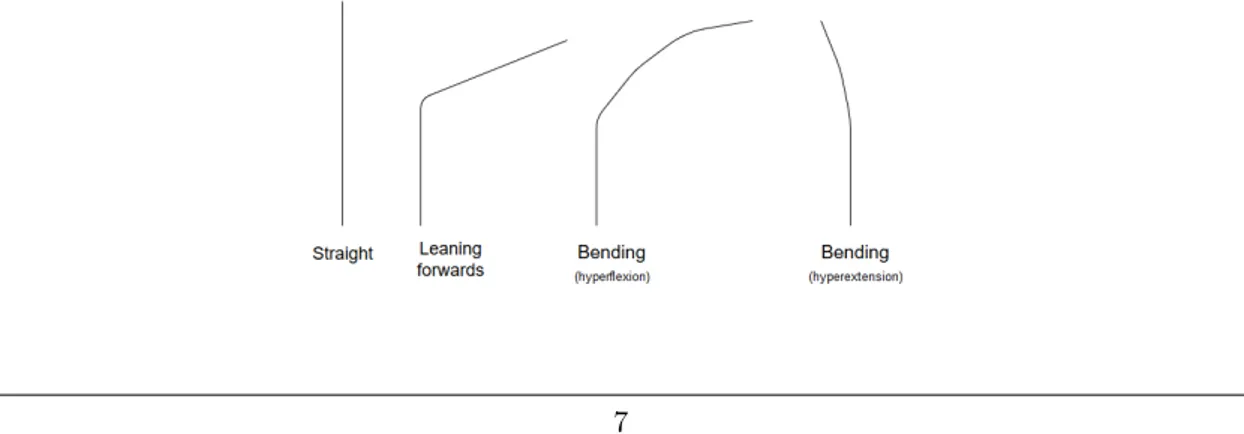
In the following sections ”hyperextension” and ”hyperflexion” will describe a bending of the back, not to be confused with leaning, in either direction that surpasses that of the reference position. The reference position is a common starting position i.e. straight back in a standing straight position.
4.1
Motivation for using IMUs
Malari´c, Hegeduˇs & Mostarac proposed in 2010 that triaxial accelerometers could be used for pos-ture and movement analysis for patients[27]. The modern Inertial measurement unit(IMU) is a triaxial accelerometer, triaxial gyroscope and triaxial magnetometer all in one. IMUs are small in size sensors that placed in the correct positions on the body could provide information about the user’s torso and back, thus indirectly measuring certain degrees of rotation or bending of the spine. Accelerometers and gyroscopes have previously been used in similar applications [2, 3, 28]. The combination of them both(inertial sensors) have also been used in multiple research projects that involve torso(or trunk) movement [29, 1, 14]. In [29] from 2010 Cuesta-Vargas et al. concluded that ”inertial sensors can offer an accurate and reliable method to study human motion, but the degree of accuracy and reliability is site and task specific”. In 2003 Lee et al. concluded that their real-time gyroscopic system for lumbar spine measurements was ”capable of producing re-liable data” [28] which indicates that the suggested implementation is even more promising. In [1] and [14] Wong and Wong used three inertial sensors for their posture monitoring experiments and ”the preliminary results demonstrated that the posture of normal subjects could be monitored and trained via this system” and ”posture of the lumbar spine in which at least 40% of the time in poor posture was reduced. Their approach was quite similar but they measured along a significantly longer portion of the spine. However, their positive results for something as complicated as posture improvement indicates that the significantly easier to measure spinal movement occurring during a of-the-ground lifting motion could certainly be possible.
4.2
Scope of thesis
Due to the limited time available during this thesis work it has been decided, in accordance with the thesis supervisor, that the thesis should focus on building a foundation for further research. This means scaling the project down to what is feasible to complete within a couple of weeks of actual implementation. It was decided that the main focus should be on the functionality of the sensors and providing some visualization of their data during lifting activities on a computer. The mobile phone implementation was deemed as not feasible due to time constraints if any proper experimentation on any test group of decent size and diversity should be prioritized. The idea is to create a basis for a system that can be integrated into the wireless body area network system proposed by Hellstr¨om et al. [30]. There is also intentions to create a sensor housing or the exper-iments will have to be conducted shirtless.
4.3
System overview
The sensor used in the project is the MPU-9250 (InvenSense, CA, U.S.A) multi-chip module that has been prepared and provided by the Embedded Sensor Systems for Health Research Profile(ESS-H) at Malardalen University. The sensors utilize the I2C communication protocol[31] to com-municate with an Arduino Uno [32] device, which in turn uses serial communication to provide MATLAB[33] with the data. Both the Arduino and MATLAB are well documented hence provid-ing a decent chance to quickly tackle many of the potential issues which can occur throughout this process.
Figure 2: The IMU-sensor platform excluding the Arduino[32] device.
4.4
Means of system validation
The first proposed means of system validation would be the estimation of an for the author unknown weight and see if the data gathered from the test group can be used to accurately estimate the load. Research has been conducted concerning how people approach an unknown compared to a known load by Burg et al.(2000) in [34]. In [35] James et al. conducted their ”Free squat” motion analysis at 40%, 60% and 80% of the maximum weight each individual could lift and their results could, by means of comparison, offer a simple indication as to the validity of the systems functionality. For a proof of concept such as this thesis however, the system functionality is best validated by whether or not it provides the expected sensor outputs in various scenarios.
4.5
Experiment procedures
Marriam-Webster defines,as of April 2016, the dead lift as ”a lift in weight lifting in which the weight is lifted from the floor to hip level”. This is the definition used in this thesis and should not be confused with the competitive version with rules and regulations that are set forth by federations such as the International Powerlifting Federation(IPF) who in their Technical Rules Book[36] have clearly specified things such as minimum and maximum allowed bar dimensions and much more. Any results obtained in these experiments should therefore be treated as such and not be compared to those obtained under competitive conditions without consideration. The instructions provided to the test group will be listed in the Results section as it will have to be coordinated with the staff and supervisors attending the experiment. The reason for selecting the deadlift over a squating motion is the added variety that comes along with different types of gripping the barbell. The deadlift does not suffer from the same personal preferences that comes along with the squat depth and bar placement during a squat. One of the major factors for the evaluation of the system in this stage will be whether or not it is able to measure extension past the reference point(hyperextension) or visually noticeable bending of the back during the flexion movement occurring during the actual lift(hyperflexion).
4.6
The Experiment
Our sensors will be attached along the spine and data will be gathered from each subject in the test group who will use kettlebells(girya) and a barbell to perform multiple heavy and light weighted deadlifts. A pronated grip will be used(i.e. both hands over the bar). They will also perform lifts with weight which for the author is unknown in order to evaluate the system and the gathered data. D.Butler et al. showed in [37] that people have a tendency to overestimate the weight at low loads and that ”people lift differently when they do and do not know the magnitude of the load lifted”. The test group is expected to be predominately male so the sensors will be placed roughly 7-8 cm apart due to the thoracic section of the spine being roughly 28 cm in the average male [38]. The weights available are various kettlebells in the 8-20kg range and a 6kg barbell with enough plates available to reach a total of 56kg. Information about the subjects dominant hand could prove valuable in case there is correlation between torso rotation angle during the mixed grip barbell lifts. Showing such a correlation could further validate the functionality or even create further system applications then the ones previously suggested in this document.
The experiment will take place on campus in a research facility so the lifting should occur on a yoga mat to ensure no damage will be done to the floor and reduce the noise in order to reduce the risk of interfering with the students or personnel in the nearby vicinity. Each participant will perform a number of lifts using both types of grip and load for sets of five. Between each set of five the subject will be asked to rest and reset their stance. In case the weights available are not enough to constitute as heavy for someone the individual will be asked to exert themselves and then try again. Flexibility or any deviations in starting position between the subjects are not taken into consideration. However, there is no known reason prior to experimentation that suggest it could become an issue. No information about clothing has been provided to the subjects prior to the experiment. The test subjects have been informed about what their task is and hence they are not expected to wear something that limits their movement or that could otherwise have a substantial impact on the results.
4.7
Analysis
The data retrieved in MATLAB[33] from the serial port was saved to a file and later post-processed into plots for visualization. Due to it being more of a proof of concept rather then a study, filtering has not been a priority and the software programmed extra I2C[31] bus added to the Arduino[32] should be slowing down the I2C communication significantly. This is however not relevant for the purposes of this thesis, it is however something that should be taken into consideration for future implementations. It should also be noted that the sensors are attached to electrodes by glue and half of a snap connector. In practice this means that the sensors are not all aligned in the same way(in any axis) and therefore their output data will be vastly different. As stated earlier however, this is a proof of concept and being able to provide a visualization of their individual data should be sufficient. In order to properly check the electronics of the system there had to be a few alterations to the PCB/Cabling setup and the plastic housing would not function for the proof of concept model so it will remain in digital form.
5
Results
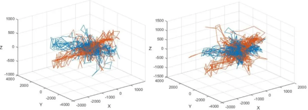
Due to some issues in both the sensor manufacturing and sensor data acquisition there were not enough time to conduct the experiments on an actual test group and have to settle for data gathered from a single individual. However, it should still be enough for a proof of concept demonstration and functionality validation. Figure3 shows the accelerometer data from two sensors during an series of over/over and over/under grip lifts with a barbell (total of 46kg). These results can be interpreted in various ways, neither should be considered to be of any value on its own as the sensors were loosely attached means that enabled a bit of swinging during motion. Also, due to the rather high requirements for mobility during the experiment the cables where not attached to the body outside of directly on the sensor, meaning that the wire could cause some swaying as well. Looking at the accelerometer data in the left part of Figure 3 it does resemble a feasible path for the sensor during a lift with the most data points being in the normal standing position with a few occurrences of overextending. Note that this is without any additional filtering. This indicates that there is a difference in the collected accelerometer data between different lifts. The differences in the corresponding gyroscope data in Figure4 is not as visually obvious, which was to be expected as it is taken over a series of lifts. To clarify, the two sensors in the graphs are the two positioned in the middle to provide the worst case due to extra cables and a small distance in between. However, already the concept does look feasible but it is hard to predict how significantly better the system might work with more time, resources and a few iterations. This also validates the hypothesis stated in the beginning: ”Providing someone with information about the position of their spine could help counteract bad posture or incorrect lifting technique, thus reducing the risk of back injuries.”
Figure 3: Accelerometer data comparison between over/under and over/over grip for two sensors during 46kg barbell lifts.
6
Discussions
This thesis aims to construct a prototype for use as a proof of concept and provide a basis for future research. The system is built by commercial components. The experiment was not as thorough as intended due to the abandonment of the test group in favour of system functionality. The feasibility of the approach to preventing back injuries or improving posture, as stated in the beginning of this document, has not diminished. Any issues or disheartening events have all been due to poor design or poor selection of equipment, both software and hardware. By adding filters, fastening the sensors properly and doing some proper cable management it could, potentially, function significantly better then in the current state. Due to the quite troublesome selection of components for the electronics there had to be a few alterations to the cable management to simplify diagnostics. This meant that the plastic housing designed would not fit and the simplified approach of just attaching the sensors to the back by electrodes was taken instead. From a data accuracy standpoints this is a terrible approach but from a system diagnostic view it worked out well. The Arduino device was functional but it would have saved a significant amount of headache to just obtain an Arduino Due instead of the Uno to get a proper second I2C bus. The suggested means of presentation is to perform the necessary pitch, yaw and roll calculations for each sensor and show the user the current angles for the sensors in comparison to a reference value (i.e. a straight back position).
6.1
Research questions
The research questions posted in 2.2 were:
What parts of the spine are prone to injuries related to bad posture or lifting? Much of the research reviewed in the Background section looks into this and it seems to depend on if it is e.g. a torsion motion, bending or lifting.
How can a user be informed if they fall within the risk zone of back injuries? The risk of certain types of back injuries, mainly those involving moving or positioning the spine, could be reduced by using a refined version of the system suggested in this document. The way of sharing the sensor location data would depend on the users technical prowess, should it be a little man bending, or would a graph suffice?.
Is it enough for the user to receive information about the current position of the spine or is a storage solution required for viewing over longer periods of time? Injuries related to lifting does in most cases require immediate feedback, while posture requires a longer period of time to really notice any improvement, hence a storage solution could be handy for comparison. Hardware issues prevention The main means to tackle potential hardware issues was to use the Arduino Uno as the I2C bus. It is a very well documented device that is popular and reasonably priced. The only issue that were significantly worse then expected was the difficulty of properly attaching the MPU9250 to the PCB due to its QFN packaging.
6.2
Novelty
For normal consumers the state-of-the-art digital product for preventing back injuries and improve posture seems to be the Lumo lift [21]. This is however a single sensor unit system, which means that it can measure angular displacement from its own location but will treat the users body as a straight line. Leaning forward or slouching, it will not be able to tell the difference. By using multiple sensors placed along the back, the proposed system could be able to tell those two movements apart, it could also differentiate between full body movements and upper body movements.
6.3
Future works
This section will feature suggestions for future works and proposes changes to the system for potential upcoming system iterations.
6.3.1 Changes to the system:
New approach to the issue of having 4 sensors in I2C with only two available addresses. Here are a few suggestions, in no particular order. First suggestion is looking into shifting the addresses so only the one you want to read holds the address to be read. Second suggestion is to try an I2C multiplexer. And if neither of those work, see if it is possible to turn two of them off while reading the other two. Otherwise find a dual I2C bus micro controller, like the Arduino Due.
6.3.2 Recreational lifting
This thesis covers the basic deadlift but same sensor system could be applied for the other vari-ations of the deadlift. Squats is another popular form of recreational lifting and in [35] Walsh et al. concluded that athletes significantly hyperextend their lumbar spines at heavier weights. Hyperextension of the lumbar could(in theory) be picked up by measuring in the thoracic spine presuming there is a reference value to compare against. It would also be beneficial to also look into the occurrence of a hyperflexion state due to insufficient tension in the core area, that being the area around the stomach. Lifting belts help ensure that this issue of tension will not occur, or at least not as easily, hence people who commonly use and are reliant on the stability provided by these belts could risk injury due to hyperflexion. The latter is only a theory by the author and should therefore be treated as such.
6.3.3 Work and miscellaneous applications
Outside of the obvious applications such as posture while conducting work at a desk or in front a computer, there are a few other potential applications for a system such as this. Just to mention a few:
Asymmetrical work e.g. lifting objects with uncommon shapes or sizes, using a shovel or maybe even cooking for long periods at a time.
Pulling or pushing above the head.
Find potential risks e.g. by combining sensors on the back with a set of sensors such as those used by Per Hellstr¨om et. al. in [39] to examine the impact of carrying asymmetrical loads for longer periods of time. One area of interest could be students carrying laptops in shoulder bags in comparison to backpacks.
Performance optimization With an open mind and some creativity the system might even be applied to what appears to be insignificant studies e.g. find the best or somehow most beneficial position for a bicyclists seat and handlebar by looking at the curvature of their back.
Clinical applications There are also some possible clinical applications e.g. rehabilitation by providing information about how much or how often a person is able to move their upper body following e.g. surgery or injury to see if there are improvements over time. It might even reduce the frequency of required doctor or orthopedist visits by sending mobility related information by phone to see if there are improvements.
6.3.4 Filtering and processing
Implement an Kalman filter in order to provide a more coherent visual representation of spinal movement could be considered. Kalman filtering is suggested simply due to the author having some small previous experience with it and does therefore not state that it is the best nor that it is the only viable option. It seems however that the go-to filter solution for IMUs is some implementation of a Kalman filter e.g. [40, 41]. With the data acquisition functional there is also the matter of representation but there are no indicators that a properly filtered signal should make it difficult to present the four sensors position to the user during activities mentioned earlier in this document. In the Related Works section there are a few who used IMUs in their experiments with success and those were post-injury in which accuracy and system functionality is even more important. There are also IMUs in completely different applications that all indicate that with enough time and resources it is possible to obtain some amazing results, significantly better then what would be required in a system like the one proposed here.
6.3.5 Replication studies
A refined system such as the one suggested in this thesis could, through minor alterations, provide the spine or back tracking functionality required for many of the studies conducted regarding the spine and torso movement. In combination with an IMU attached to the back of the head it would be possible to conduct additional replication studies in regards to posture.
7
Conclusion
This is a master thesis which set out to develop a basic proof of concept prototype for measuring along the human spine. The prototype and previous IMU implementations, such as in airplanes, indicate that the approach has great potential and given more time and resources it seems feasible that the system described in the beginning of this document could be created. This thesis also shows that a basic form of such a system can be created with commercial off the shelf components and there are no reasons to belive that any major issues would occur moving over to a wireless system in order to be a part of the system suggested in [30].
8
Acknowledgments
First i would like to express my gratitude to both my supervisors Martin Ekstr¨om and Maria Ehn who have shown unwavering support throughout this master thesis. I would also like to thank Lennie Carl`en Eriksson and Per Hellstr¨om for their assistance in acquiring the equipment required to prevent the thesis project from temporarily slowing down.
9
Initial time-plan
1. Start date: January 18, 2016
2. Week 1-4: Reading various material and related works 3. Week 5-8: Designing and simulations
4. Week 9-13: Actual implementation
5. Week 14-16: Testing and evaluation of both the design and implementation 6. Week 17-20: Dedicated towards finishing the thesis
References
[1] W. Y. Wong and M. S. Wong, “Trunk posture monitoring with inertial sensors,” European Spine Journal, vol. 17, no. 5, pp. 743–753, 2008. [Online]. Available:
http://dx.doi.org/10.1007/s00586-008-0586-0
[2] A. Lopez-Quintana, J. Tejero-Calado, and F. Vidal-Verdu, “Accelerometer array and method to obtain a 3d representation of the spine posture,” in Broadband and Wireless Computing, Communication and Applications (BWCCA), 2011 International Conference on, Oct 2011, pp. 466–471.
[3] A. Crane, S. Doppalapudi, J. O’Leary, P. Ozarek, and C. Wagner, “Wearable posture detection system,” in Bioengineering Conference (NEBEC), 2014 40th Annual Northeast, April 2014, pp. 1–2.
[4] L. Dunne, P. Walsh, B. Smyth, and B. Caulfield, “Design and evaluation of a wearable op-tical sensor for monitoring seated spinal posture,” in Wearable Computers, 2006 10th IEEE International Symposium on, Oct 2006, pp. 65–68.
[5] A. Torn, “Muscle activity and range of motion during active trunk rotation in a sitting posture,” Applied Ergonomics, vol. 32, no. 6, pp. 583 – 591, 2001. [Online]. Available:
http://www.sciencedirect.com/science/article/pii/S0003687001000400
[6] B. P. B. L. v. d. W. G. Arins GAM, van Mechelen W, “Physical risk factors for neck pain,” Scandinavian Journal of Work, Environment & Health, vol. 26, no. 1, pp. 7–19, 2000. [7] B. El-Sayed, N. Farra, N. Moacdieh, H. Hajj, R. Haidar, and Z. Hajj, “A novel mobile wireless
sensing system for realtime monitoring of posture and spine stress,” in Biomedical Engineering (MECBME), 2011 1st Middle East Conference on, Feb 2011, pp. 428–431.
[8] J. C. R. T. R. N. R. W. D. Daynard, A. Yassi, “Biomechanical analysis of peak and cumu-lative spinal loads during simulated patient-handling activities: a substudy of a randomized controlled trial to prevent lift and transfer injury of health care workers,” Applied Ergonomics, vol. 32, no. 3, pp. 199–214, 2001.
[9] K. Naruse, S. Kawai, and T. Kukichi, “Three-dimensional lifting-up motion analysis for wear-able power assist device of lower back support,” in Intelligent Robots and Systems, 2005. (IROS 2005). 2005 IEEE/RSJ International Conference on, Aug 2005, pp. 2959–2964. [10] S. M. McGill, “The biomechanics of low back injury: Implications on current practice in
industry and the clinic,” Journal of Biomechanics, vol. 30, no. 5, pp. 465–475, 2016/03/06 XXXX. [Online]. Available: http://dx.doi.org/10.1016/S0021-9290(96)00172-8
[11] M. Jonathan Cluett. (2016, Feb.) How to lift. [Online]. Available: http://orthopedics.about. com/cs/backpain/ht/lift.htm
[12] S. M. Hsiang, G. E. Brogmus, and T. K. Courtney, “Low back pain (lbp) and lifting technique a review,” International Journal of Industrial Ergonomics, vol. 19, no. 1, pp. 59 – 74, 1997. [Online]. Available: http://www.sciencedirect.com/science/article/pii/0169814195000860
[13] “LilyPad Arduino 328 website,”https://www.arduino.cc/en/Main/arduinoBoardLilyPad, ac-cessed: 2016-05-18.
[14] W. Y. Wong and M. S. Wong, “Smart garment for trunk posture monitoring: A preliminary study,” Scoliosis, vol. 3, no. 1, pp. 1–9, 2008. [Online]. Available:
http://dx.doi.org/10.1186/1748-7161-3-7
[15] T. B. Byrgesen, M. L. Skov, M. J. S. Yeoman, and F. Yu, “Dynamic posture correcting device used for rehabilitation exercises,” International Journal of Integrated Care, vol. 15, no. 7, 2015. [Online]. Available: http://www.ijic.org/index.php/ijic/article/view/URN%3ANBN%
[16] F. Yu, A. Bilberg, L. Xiao, and K. B. Yderstraede, “Foot edema simulation and monitoring using dielectric electro-active polymer sensors,” Sensors and Actuators A: Physical, vol. 225, pp. 33 – 40, 2015. [Online]. Available: http://www.sciencedirect.com/science/article/pii/ S092442471500062X
[17] W. Xu, Z. Li, M.-C. Huang, N. Amini, and M. Sarrafzadeh, “ecushion: An etextile device for sitting posture monitoring,” in Body Sensor Networks (BSN), 2011 International Conference on, May 2011, pp. 194–199.
[18] E. Sardini, M. Serpelloni, and M. Ometto, “Smart vest for posture monitoring in rehabilitation exercises,” in Sensors Applications Symposium (SAS), 2012 IEEE, Feb 2012, pp. 1–5. [19] D. Y. Eric S. Hald, Richard W. Hertle, “Development and validation of a digital head posture
measuring system,” American Journal of Ophthalmology, vol. 147, no. 6, pp. 1092–1100, 2009. [20] T.-L. Le, M.-Q. Nguyen, and T.-T.-M. Nguyen, “Human posture recognition using human skeleton provided by kinect,” in Computing, Management and Telecommunications (Com-ManTel), 2013 International Conference on, Jan 2013, pp. 340–345.
[21] “Lumolift website, product page,”http://www.lumobodytech.com/lumo-lift, accessed: 2016-05-18.
[22] “iPosture website, product page,”http://www.iposture.com/, accessed: 2016-05-18.
[23] “BAX-U Posture corrector website, product page,”http://www.bax-u.com/, accessed: 2016-05-18.
[24] “Beast sensor website, product page,”https://www.thisisbeast.com/en, accessed: 2016-05-18. [25] M. Bergblomma, M. C. Ekstr¨om, M. Ekstr¨om, J. G. Casta˜no, M. Bj¨orkman, and M. Lind´en, World Congress on Medical Physics and Biomedical Engineering, September 7 - 12, 2009, Munich, Germany: Vol. 25/5 Information and Communication in Medicine, Telemedicine and e-Health. Berlin, Heidelberg: Springer Berlin Heidelberg, 2009, ch. Wireless ECG Network, pp. 244–247. [Online]. Available: http://dx.doi.org/10.1007/978-3-642-03904-1 68
[26] Unknown, “The ethical review act.” [Online]. Available: http://www.epn.se/media/1205/ the ethical review act.pdf
[27] R. Malari´c, H. Hegeduˇs, and P. Mostarac, Advances in Biomedical Sensing, Measurements, Instrumentation and Systems. Berlin, Heidelberg: Springer Berlin Heidelberg, 2010, ch. Use of Triaxial Accelerometers for Posture and Movement Analysis of Patients, pp. 127–143. [Online]. Available: http://dx.doi.org/10.1007/978-3-642-05167-8 9
[28] R. Y. Lee, J. Laprade, and E. H. Fung, “A real-time gyroscopic system for three-dimensional measurement of lumbar spine motion,” Medical Engineering & Physics, vol. 25, no. 10, pp. 817–824, 2003. [Online]. Available: http://www.sciencedirect.com/science/article/pii/ S1350453303001152
[29] W. J. Cuesta-Vargas AI, Galn-Mercant A, “The use of inertial sensors system for human motion analysis,” Physical Therapy Reviews, vol. 15(6), pp. 462–473, 2010.
[30] P. Hellstr¨om, L. C. Eriksson, J. S. Willners, M. Folke, and M. Ekstr¨om, “Intelligent wireless body area network system for human motion analysis,” in 1st International Conference on Smart Portable, Wearable, Implantable and Disability-oriented Devices and Systems. (IARIA) XPS. [Online]. Available:
[33] “Mathworks MATLAB website, product page,”http://se.mathworks.com/products/matlab/, accessed: 2016-05-18.
[34] J. van der Burg, J. van Dien, and H. Toussaint, “Lifting an unexpectedly heavy object: the effects on low-back loading and balance loss,” Clinical Biomechanics, vol. 15, no. 7, pp. 469–477, 2000. [Online]. Available: http://www.sciencedirect.com/science/article/pii/ S0268003399000844
[35] J. C. Walsh, J. F. Quinlan, R. Stapleton, D. P. FitzPatrick, and D. McCormack, “Three-dimensional motion analysis of the lumbar spine during free squat weight lift training,” The American Journal of Sports Medicine, vol. 35, no. 6, pp. 927–932, 2007. [Online]. Available: http://ajs.sagepub.com/content/35/6/927.abstract
[36] Unknown, “International powerlifting federation. technical rules book 2015. updated nov 24, 2014,” http://www.powerlifting-ipf.com/fileadmin/ipf/data/rules/technical-rules/english/ 2015 V2 IPF Technical Rules Book 2015 classic rules in back section.pdf, online; Accessed at 2016-04-11.
[37] D. BUTLER, G. B. J. ANDERSSON, J. TRAFIMOW, O. D. SCHIPPLEIN, and T. P. ANDRIACCHI, “The influence of load knowledge on lifting technique,” Ergonomics, vol. 36, no. 12, pp. 1489–1493, 1993, pMID: 8287855. [Online]. Available: http: //dx.doi.org/10.1080/00140139308968016
[38] H. Gray. (1918) Anatomy of the human body. [Online]. Available: http://www.bartleby.com/ 107/25.html
[39] P. Hellstrom, M. Folke, and M. Ekstrm, “Wearable weight estimation system,” Procedia Computer Science, vol. 64, pp. 146 – 152, 2015, conference on {ENTERprise} Information Systems/International Conference on Project MANagement/Conference on Health and Social Care Information Systems and Technologies, CENTERIS/ProjMAN / {HCist} 2015 October 7-9, 2015. [Online]. Available: http://www.sciencedirect.com/science/article/pii/ S1877050915026101
[40] G. Ligorio and A. Sabatini, “A novel kalman filter for human motion tracking with an inertial-based dynamic inclinometer,” Biomedical Engineering, IEEE Transactions on, vol. 62, no. 8, pp. 2033–2043, Aug 2015.
[41] J. Lambrecht and R. Kirsch, “Miniature low-power inertial sensors: Promising technology for implantable motion capture systems,” Neural Systems and Rehabilitation Engineering, IEEE Transactions on, vol. 22, no. 6, pp. 1138–1147, Nov 2014.
![Figure 2: The IMU-sensor platform excluding the Arduino[32] device.](https://thumb-eu.123doks.com/thumbv2/5dokorg/4829650.130298/10.892.253.640.127.416/figure-imu-sensor-platform-excluding-arduino-device.webp)