LICENTIATE THESIS
Tribological and Mechanical Behaviour of
Lamellar and Compacted Graphite Irons
in Engine Applications
ROHOLLAH GHASEMI
Department of Materials and Manufacturing
SCHOOL OF ENGINEERING, JÖNKÖPING UNIVERSITY Jönköping, Sweden 2015
Tribological and Mechanical Behaviour of Lamellar and Compacted
Graphite Irons in Engine Applications
Rohollah Ghasemi
Department of Materials and Manufacturing School of Engineering, Jönköping University SE-551 11 Jönköping, Sweden
Rohollah.Ghasemi@jth.hj.se Copyright © Rohollah Ghasemi
Research Series from the School of Engineering, Jönköping University Department of Materials and Manufacturing
Dissertation Series No. 5, 2015 ISBN 978-91-87289-06-4
Published and Distributed by
School of Engineering, Jönköping University Department of Materials and Manufacturing SE-551 11 Jönköping, Sweden
Printed in Sweden by
Ineko AB Kållered, 2015
i
ABSTRACT
There has been much discussion about the beneficial uses of lamellar graphite iron in piston rings–cylinder liner systems, where a good combinations of both thermal and tribological properties are essential. The excellent tribological performance of lamellar iron under such sliding conditions is principally associated with lubrication behaviour of the graphite particles which are distributed as lamellas throughout the matrix. During sliding, graphite particles are extruded and smeared onto the counterfaces, act as solid lubricating agents and form a thin graphite film between the sliding surfaces. Although this process especially, during the running-in period significantly changes the sliding wear response of the components, the exact mechanism behind of this phenomenon has rarely been discussed in previous studies. It is tribologically beneficial to keep the graphite open, particularly in applications where the scuffing issues do matter. In this thesis, the main causes involved in closing the graphite lamellas are discussed, with a focus on matrix plastic deformation that occurs during sliding. In first step, the relationship between graphite lamellae orientation and plastic deformation was investigated. To do so, two piston rings, belonging to the same two-stroke marine engine operated for different periods of time, were selected and compared to the unworn sample. The worn piston rings displayed a substantial decrease in both frequency and area fraction of the graphite lamellas. Most of the lamellas were closed as a result of plastic deformation of matrix. This happening was caused mainly by the interaction between abrasive particles and metallic matrix. Additionally, it was found that graphite lamellas parallel or near-parallel to the sliding direction exhibited maximum closing tendency under sliding condition.
In next step, to have a better understanding of the graphite film formation mechanism and matrix deformation role in closing the graphite lamellas, microindentation and microscratch testing were performed on typical lamellar iron. The qualitative results showed a similar mechanism involving in graphite contribution to lubricate the sliding surfaces. Moreover, microindentations made nearby the graphite lamellas demonstrated that the deformation of the matrix causes the formation of cracks in the centre of the graphite lamellas, compressing and then extruding the graphite from its natural position, irrespective of the lamellas′ size. Furthermore, it was found that subsurface graphite orientation had a large influence on the extrusion behaviour, in that, for graphite lamellas oriented towards the indenter, the effect was observed more pronounced.
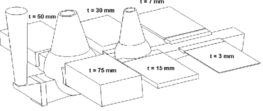
Furthermore, an improved fully ferritic solution strengthened compacted graphite iron was produced for future wear studies. The effects of different Si levels and section thicknesses on tensile properties and hardness were investigated as well. The influence of Si content and section thickness on mechanical properties was revealed by improving the materials strength and slightly enhancing the hardness through increasing Si content. Besides, Si addition up to 4.5 wt% significantly affected the strength and elongation to failure of cast samples.
Keywords: Sliding wear, abrasive wear, graphite lubricating performance, matrix
iii
ACKNOWLEDGEMENTS
I would like to express my sincere gratitude and acknowledgements to several people who have helped me during my licentiate studies:
Anders E. W. Jarfors; From the beginning, you gave me enormous support and helped me with
both scientific and personal matters. As my supervisor, you showed how important my issues and personal concerns were to you. Thank you for providing me with a stress-free work environment during my studies. It was very enjoyable to work with you; I always felt welcome in your office, and our discussions usually ended with me being more relaxed, encouraged, and somehow wiser.
Lennart Elmquist; It is difficult for me to explain exactly how much I enjoyed my licentiate
time at JTH as a result of your presence. I highly appreciate your comments, input, and ideas. The challenging discussions we had before submitting each paper always showed the vast extent of your patience. The scientific work which we started together is as-yet unfinished, and I look forward to seeing the continuation of this work in the future.
Ingvar L. Svensson; Although we had very little chance to work together directly, I enjoyed the
benefit of your support and guidance during my licentiate. Thank you for always being available to answer my questions.
Nils-Eric Andersson and Emma Sjölander; Thank you for teaching me about SEM and EDS
analysis in the lab. You were available at all of the times when I needed help. Emma, I enjoyed your discussions on different matters and our funny Swedish conversations.
Toni Bogdanoff; Many thanks for your enjoyable company during my visiting and training at the
Micro-materials in the UK. You were always very active, fresh, welcoming, and ready to assist me with my experiments in the lab, and you did a great job in fixing the equipment failures!
Esbjörn Ollas and Lasse Johansson; I deeply appreciate your teaching and assistance with the
experimental equipment.
Taishi Matsushita; Thanks for your valuable discussions and comments, in particular on the
statistical analysis methods.
Saman Hosseinpour; You have been my best friend since I came to Sweden. Thank you for your
helpful scientific comments and invaluable personal advice, which has helped me during difficult times. You had a great influence on my motivation to work hard and never give up during my Master′s and, more importantly, licentiate studies.
Thank you to all of my past and present colleagues and friends at the department of Materials and Manufacturing at the School of Engineering, Jönköping University. I enjoyed all of our Monday meetings and seminars, trips, and coffee breaks.
Thank you to all of my friends at MAN Diesel & Turbo in Denmark, and those at Uppsala University who were involved in the Helios project; for good co-operation, providing the
iv
materials, and supporting me with your valuable comments, especially during the first year of my studies.
Thanks are also due to my friends involved in the FFI project, especially Swerea SWECAST, Volvo Powertrain AB, and SinterCast AB, who have helped me with experimental work. The European Research Council (ERC) and the Knowledge Foundation (KK) are gratefully acknowledged for financial support.
Finally, I would like offer my sincerest gratitude to my beloved family, especially my wife, for their invaluable support, encouragement, and endless patience. I love you all.
v
SUPPLEMENTS
The following supplements constitute the basis for this thesis.
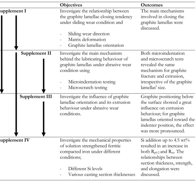
Supplement I R. Ghasemi, L. Elmquist, The Relationship Between Flake Graphite Orientation, Smearing Effect, and Closing Tendency under Abrasive Wear Conditions, Wear, 317 (1-2), 2014, pp. 153-162.
Ghasemi was the main author. Elmquist contributed with advice regarding the work.
Supplement II R. Ghasemi, L. Elmquist, A Study on Graphite Extrusion Phenomenon under the Sliding Wear Response of Cast Iron Using Microindentation and Microscratch Techniques, Wear, 320 (1-2), 2014, pp. 120-126.
Ghasemi was the main author. Elmquist contributed with advice regarding the work.
Supplement III R. Ghasemi, L. Elmquist, Cast Iron and Self-Lubricating Behaviour of Graphite under Abrasive Wear Conditions, Proceeding of SPCI 10, November 10-13th, 2014, Mar Del Plata,
Argentina.
Ghasemi was the main author and presented the work at the 10th International Symposium on the Science and Processing of Cast Iron, Mar Del Plata, Argentina, 10-13th November
2014. Elmquist contributed with advice regarding the work.
Supplement IV R. Ghasemi, L. Elmquist, H. Svensson, M. König, A. E. W. Jarfors, Mechanical Properties of Solid Solution Strengthened Compacted Graphite Iron, Proceeding of SPCI 10, November 10-13th, 2014, Mar Del Plata, Argentina.
Ghasemi was the main author and carried out all the mechanical properties measurements. Elmquist and Jarfors proposed the work and contributed with advice concerning the work. Jarfors contributed with advice concerning the work and helped in the evaluation of the results. Svensson performed the image analysis. König contributed to designing the casting′s pilot model. The work was presented by Jarfors at the 10th International Symposium on the Science and Processing of Cast Iron, Mar Del Plata, Argentina, 10-13th November 2014.
vii
TABLE OF CONTENTS
CHAPTER 1: INTRODUCTION ... 1
1.1 BACKGROUND ... 1
1.2 CLASSIFICATION OF WEAR MECHANISMS AND WEAR MODES ... 2
1.3 MECHANICAL BEHAVIOUR OF CAST IRONS ... 7
1.4 TRIBOLOGICAL BEHAVIOUR OF CAST IRONS ... 12
CHAPTER 2: RESEARCH APPROACH ... 17
2.1 PURPOSE AND AIM ... 17
2.2 RESEARCH DESIGN ... 18
2.3 MATERIAL AND EXPERIMENTAL PROCEDURE ... 20
CHAPTER 3: SUMMARY OF RESULTS AND DISCUSSION ... 25
3.1 ON THE WEAR OF PISTON RING MATERIALS (SUPPLEMENT I) ... 25
3.2 EXTRUSION BEHAVIOUR OF GRAPHITE (SUPPLEMENTS II & III) ... 30
3.3 SOLUTION STRENGTHENED COMPACTED GRAPHITE IRON (SUPPLEMENT IV) ... 34
CHAPTER 4: CONCLUDING REMARKS ... 39
CHAPTER 5: FUTURE WORK... 41
REFERENCES...… ... 43
1 CHAPTER 1
INTRODUCTION
CHAPTER INTRODUCTION
The chapter starts with a short introduction to the different wear types which occur under sliding conditions in general, and then narrows to deal with the piston ring–cylinder liner application. However, due to its complexity, it will not be possible to fully discuss the wear process during sliding, and this was not the target of the study; rather, it was intended to highlight the contribution of graphite lamellas on improvements in tribological performance of cast iron components, especially, lamellar iron under abrasive wear conditions.
1.1 BACKGROUND
'Tribology', in simple way; is related to the science and engineering of the gradual surface failure phenomenon which is intimately encountered friction, wear, lubrication, adhesion, surface fatigue, erosion, etc. Tribological design and material selection play vital roles in the performance, operation, and durability of all mechanical machines that are under sliding conditions [1]. As been discussed a lot in literature [2-4], wear is known as one of the most undesirable phenomenon in industrial contexts. It occurs as a successive degradation process at the interfaces between interacting parts under sliding such as brakes, clutches, piston rings, and cylinder liners.
In tribosystems, the high level of friction which is generated by the sliding surfaces is usually immediately accompanied by a dramatic increase in coefficient of friction and surface temperature [5]; the consequences of this, i.e. the result of the high shear stress induced on the sliding surfaces, is plastic deformation of the matrix [6]. In complex applications, where the components have to withstand high pressures and temperature (such as piston rings and cylinder liner systems), frictional heat and wear are potentially considered to be the critical issues [3]. Thus, improved wear-resistant coating, surface treatment, and lubrication options are generally suggested as beforehand solutions to improve the wear resistance and tribological performance of materials [7]. Besides, initial operating conditions such as oil clearance [8] and the running-in surface texture [9] are important factors in determining the wear resistance of the sliding parts. Moreover, it is now well-known that all types of wear and friction are affected by the thin film of materials (solid lubricating agents) which forms between the interfering surfaces and separates contacting surfaces in relative motions [10]. This layer controls wear process to a large extent and is most often beneficial as it reduces friction and wear however, there exist some cases in which film formation causes an increase in friction and wear [5, 11]. In addition, from the microstructural standpoint, metal matrix significantly affects the mechanical properties and tribological behaviour of materials; this may include deformation and fracture mechanisms, as well as the friction and sliding wear response of the bodies under sliding conditions [12].
2
1.2 CLASSIFICATION OF WEAR MECHANISMS AND WEAR MODES
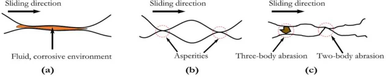
Progressive removal of material from a surface, transfer of material from one surface to another, or displacement of the material within a single surface are the broadest definitions of wear [13, 14]. It is worth mentioning that wear is not a material property [15]; rather, it is a system response which can vary depending on contact conditions such as counterpart stiffness [16, 17], contact shape [18], sliding velocity [19], temperature [20, 21], and the presence or absence of lubricant [22, 23]. Wear classification has always been a challenge due to the complexity, overlapping, and interrelationships between the wear processes; hence, the terminology and definitions related to the wear are continually updated by the latest scientific and empirical observations. Many different wear mechanisms have been identified and proposed. Based on the relative importance in engineering practice, different types of wear mechanisms have been classified in the literature; these include abrasive, adhesive, corrosive, surface fatigue, oxidative, and erosive wear. Corrosive wear is considered to be a descriptive expression for chemical wear, while adhesive and abrasive are more commonly thought of as aspects of mechanical wear [15]. These three wear mechanisms, as schematically shown in Figure 1, are the most commonly encountered in piston ring–cylinder liner parts [3, 10], and are described briefly here.
Figure 1.Schematic depicting the possibilities of material removal under sliding condition; (a) corrosive attack, (b) adhesive wear, and (c) abrasive wear caused either by two- or
three-abrasion mechanisms. 1.2.1 Corrosive wear
The corrosive wear phenomenon has recently received a considerable increase in attention, although it still lags behind abrasive and adhesive wear in research efforts [3, 24]. It involves material removal or loss by oxidative chemical reaction of the metal surface in the presence of corrosive environment which could be encountered as air (unlubricated) or liquid base (lubricated), illustrated in Figure 1(a). Under unlubricated conditions, the removal of material is mainly controlled by the mechanical process after oxidation due to the presence of humidity, O, and other industrial vapours. In these circumstances, metal oxide and hydroxide are the corrosion products; thus, it is commonly referred to as oxidative wear. However, the deposited carbonate compound formation also commonly occurs with metallic components operating in an open atmosphere [25]. The corrosion-produced constituents adhere relatively loosely to the base metal, which cannot withstand even under the mildest of sliding conditions; hence, they are continuously removed from the metal surfaces during sliding. While under boundary lubricated conditions, the chemical attack may also result from the oxidation of a lubricant, which causes the formation of organic acids [3, 25]. In this case, the components slide against one another in a corrosive environment, as happens in a piston ring–cylinder liner system, in which both a chemical reaction and sliding conditions occur simultaneously. Given the liquid environment, the most common environment aqueous, even a very small quantity of dissolved gas such as CO2 causes a variation in the chemical and
3
layer is called a tribofilm. It has been confirmed that the total amount of dissolved O in water markedly affects the film formation of the hydrate or hydroxide. However, the presence of some aggressive substances, such as chloride in offshore and marine service applications, might result in formation of very common corrosion products, such as chlorides and oxychloride compounds [25].
1.2.2 Adhesive wear
As Figure 1(b) demonstrates, adhesion is related to the material transfer from one contacting surface to another. This type of wear occurs due to high surface energies; when two nominally flat surfaces have either continuous or discontinuous relative motion against one another, such that the pressure developed between the asperities is high enough to cause local plastic deformation, and thus removal of the material [3]. There are a number of physical and chemical processes which cause material loss by wear. During sliding, direct and continuous contact between the original interfaces or asperities, which are the weakest areas [26], can result in plastic shearing and the transferring of a material fragment from one surface (softer) to the other surface (harder). The consequence of successive loading and unloading processes will be an increase in friction force and plastic deformation, which in most cases is accompanied by the gradual formation of metal loose particles (i.e. debris) in the form of either individual or agglomerated detached particles [25]. These metallic particles observed on worn surfaces are indications of severe plastic deformation happened on sliding bodies. Irregularity and a blocky appearance are the most characteristics of these transferred fragments. In the worst-case scenario, severe adhesion manifests as scuffing and micro-welding issues in engineering components. Other mechanisms behind the debris formation have been discussed by Bhushan [27]. According to Archard [26] suggestion, wear equations for adhesive wear are given by the following expressions:
s V
WL ( 1 ) vWL
V
K
H
( 2 )where V (mm3/m) is the wear volume, W (N) load, L (m) sliding distance, wear rate
s (wearvolume/load×sliding distance), and K wear coefficient as the fraction of the real contact area so that (sHv) where Hv(kg/mm2) is the hardness index. Note that if the distance is the
result of sliding at constant velocity ν (m/s) such as piston ring applications, it is then given by L=νt where t indicates the sliding time.
In the case of adhesive wear, studies have demonstrated the increase in wear volume by increasing the load and sliding distance; however, no precise physical model has been found to describe the variation of K and
S, where, for example, a large variation, from 10-2 to 10-10mm3/Nm, is seen in experimental results from the same material. Such variation could be
linked to the material microstructure, local contamination, surface finish roughness, and tribofilm formation [15]. In piston rings and cylinder liner parts, adhesive wear mostly occurs during the very early stages of operating, or in conditions of insufficient lubrication. It is highly influenced by factors such as lubricating oil conditions, piston ring clearances, metal surface finishing, as well as the nature of the materials in contact [15]. Scuffing is almost always accompanied by a substantial abrupt increase in friction force [1], together with a severely plastic deformation of the matrix [28]. This is due to the high local friction originating from the direct contact between the sliding bodies. Scuffing, as an undesirable
4
consequence of adhesive wear, appears in the form of either micro-welding and/or severe wear scars. In that, these instances represent the manifestations of severe plastic deformation on sliding surfaces [29].
1.2.3 Abrasive wear
Abrasion usually takes place when asperities on a hard surface act as a hard abrasive (i.e. an indenter tip), or when the hard solid particles become confined between the sliding surfaces; (see Figure 1(c)), this leads to the indenting, scratching and damaging of the contacting interface. The smooth surface typically turns into roughened with fairly parallel grooves [30]. Severe plastic deformation and brittle fracture are observed to be two commonplace mechanisms of abrasive wear process in brittle materials [25]. In soft materials (high fracture toughness), scratches to the surface typically occur along with the deformation of the metal matrix, while in brittle materials (low fracture toughness), wear normally appears in the form of brittle fracture and cracking marks on worn surfaces.
Abrasive wear may manifest as one of two modes; either two-body or three-body abrasions mechanisms [31, 32]. With the former, hard, rough particles become embedded in one or both (in the case of materials with the same hardness) of the sliding surfaces, leading to scratching of the softer surface. In the latter, however, the hard particles move freely between the sliding surfaces. As discussed above, the abrasive particles must be sufficiently harder than either one or both of the sliding surfaces in order to scratch them [33]. Goddard et al. [34] indicated that the shape and attack angle of the abrasive particles are other important parameters in determining the severity of the wear as during both two- and three-body abrasions only a small fraction of the particles cause wear [3].
During the abrasion of a ductile component, material removal from the surface typically involves the creation of a series of grooves which run parallel to the scratching direction. On the effect of hardness on abrasive wear resistance, first studies carried out by Khruschov [35, 36] showed that for pure metals, the wear resistance is linearly proportional to materials hardness, however the order of magnitude of this relationship is changed as the microstructure changes. So that, for heat treated steel samples, increasing the hardness was accompanied with increase of wear resistance but less than that of pure metals at the same hardness [36]. It has also been known that he higher the particle hardness, the higher the rate of abrasive wear [37, 38]. Moreover, studies carried out by Bhushan et al. [39] showed that, in most cases, the process of wear begins with the adhesion mechanism, resulting in the formation of abrasive particles, and continues with the three-body abrasive mechanism. Based upon the fracture toughness, abrasive wear micro-mechanisms can be classified as being caused by plastic deformation and occur as a consequence of the fracture, where the latter case is most common in ceramic materials and metals with low fracture toughness [27].
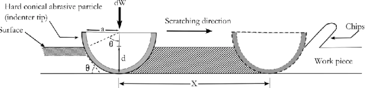
Figure 2. Schematic representation of a hard conical indenter when is scratching a soft material surface.
5
Single-pint scratch testing is usually employed to study the integrity of coated substrates as well as abrasive wear behaviour of materials. Figure 2 schematically illustrates the abrasive wear of a typical ductile material, caused by a hard abrasive particle (indenter with conical tip). Similar to adhesive wear, in abrasive wear, the wear volume equation for single-point scratch is expressed as follows: v
WL
V
H
( 3 )Here, the (shape factor of the asperities or abrasive particles) and (degree of wear by abrasive particle) values are experimentally given as 0.1, and between 0 and 1.0, respectively. However, the shear strength at the contact interface, degree of penetration, and mechanical properties of the material influence the value [40]. Therefore,
s v
H
( 4 ) and s v K
H
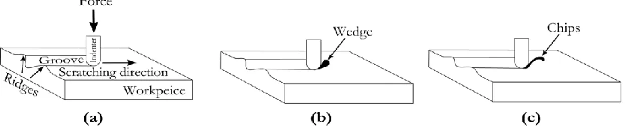
( 5 )In terms of the abrasive wear of metals, the micro-level observations from scratch tests performed on metals with high fracture toughness reveal that material removal could appear as micro-ploughing, wedge formation, and cutting on the affected surface, demonstrated schematically in Figure 3 [41].
Figure 3. Schematic of different abrasive wear modes as a consequence of plastic deformation; (a) micro-ploughing, (b) micro-wedge formation and (c) micro-cutting.
In the case of micro-ploughing (also called ridge formation), shown in Figure 3(a), the displacement and plastic deformation of the softer material occurs along the groove sides without the removal of material also called (ploughing zone). This mechanism, which lacks the generation of wear particles, is typically considered as a moderate and steady state of abrasive sliding [15]. However, Kitsunai et al. [42] demonstrated that, in the case of further repetitive abrasive contact, ploughing leads to material flow, and removal occurs due to the cyclic fatigue mechanism. Under repeated sliding conditions, the ridged regions become flattened and eventually fracture, which significantly intensifies the debris formation rate. Besides surface deformation, in most cases the scratching of the surface results in subsurface plastic deformation, directed against the surface, and subsurface crack nucleation. Increasing the load during sliding gives rise to the propagation of the pre-existing cracks parallel to the surface so that, under a given shear stress condition, wear plates are formed. Therefore, wear particles and wear platelets are produced as a result of the ridge feature and generation, and propagation of surface and subsurface cracks, respectively.
6
The wedge formation mechanism, see Figure 3(b), relates to the transition between micro-ploughing and micro-cutting [43]. It generally appears when the interface shear strength ratio relative to the bulk shear strength is high, i.e. between 0.5-1. This model was theoretically introduced by Challen and Oxley [44], and later validated experimentally by Hokkirigawa et al. [41]. However, wedge formation does not lead to high wear; rather, it causes a high frictional resistance, and is important issue during grinding [45]. In this situation, only a small part of the material is displaced as a ridge during the scratching of a surface by a hard abrasive particle, so that the rest of the deformed matrix develops as a wedge in front of the abrasive tip, and is removed in a similar manner to the cutting mechanism.
However, the micro-cutting mechanism is connected to the extremely severe abrasive wear conditions that occurs when a hard particle, such as an asperity or debris with a large attack angle, as seen in Figure 3(c) [46], similar to the cutting tool, ploughs the surface to such an extent that the entirety of the removed material reappears in the form of a microchips (ribbon-shaped) ahead of the abrasive tip [30]. Adhesion takes place between the front face of the abrasive particle and the matrix, which influences the displacement response of the material to the sides of the groove to a great extent [41]. In addition to the hardness impact of the particles [37, 38] and the morphology of the abrasive particle [47], the transition from ploughing and wedge formation to cutting mechanism is strongly influenced by the applied load [41], attack angle [46], degree of penetration, interfacial shear strength of the interface [30], and size [30, 47, 48] of the abrasive particles so that, for example, very small abrasive particles produce such fine scratches as to result in a polished appearance [6]. A significant amount of material is removed during the scratching of the component, even though the size of the remaining grooves is very small. An increase in penetration depth is accompanied by an increase in the coefficient of friction, as these are the critical factors affecting and determining the presented transition [41].
Figure 4. Schematic illustration of abrasive wear modes (introduced by Zum-Gahr [30]) embedded in deformation modes as a consequence of plastic deformation (theoretically
calculated by Challen and Oxley [44]).
Various abrasive wear modes are described by the deformation modes diagram, in which for example, the scratching process of a surface using a hard, spherical indenter is described as a function of different degrees of penetration, effective attack angle of the sphere, and normalised interfacial shear strength [30]. For instance, Figure 4 demonstrates the
7
deformation modes theoretically identified via scratching a surface by a hard spherical indenter [41], where f =contact interface shear strength/wear material shear strength and DP = indentation depth/contact radius.
1.3 MECHANICAL BEHAVIOUR OF CAST IRONS
'Cast iron' as a term is, in essence, used to identify a group of a binary Fe-C or multicomponent Fe-X-C ferrous alloys which normally contains more than 2 wt% C and about 1 to 3 wt% Si. However, Mn, S, and P are usually observed as minor alloying elements as well [49]. In order to achieve a cast iron with required mechanical, physical, and tribological properties, normal cast iron can be alloyed through the addition of Si, Ni, and Mn up to certain levels [50-52] so as to satisfy basic structural requirements, i.e. amount, shape, size, and distribution of graphite particles [53], along with a defined matrix [54, 55]. Cast irons can be categorised based on the graphite morphology and metal matrix structure.
1.3.1 On graphite morphologies
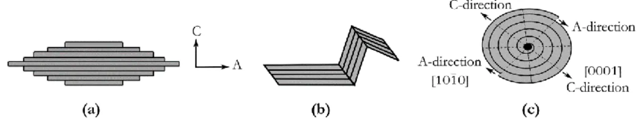
Figure 5(a) illustrates the ideal crystalline structure of graphite which consists of the honeycomb-like hexagonal layered structure parallel to the basal plane and faceted crystals bounded by low index planes. Carbon atoms are linked by a strong covalent chemical bonding to the three adjacent carbon atoms, while the carbon monolayers are linked by weak long-ranged van der Waals forces [56].
Figure 5. Schema of (a) graphite with layered structure, (b) possible graphite growth in A- and C-direction [53, 57].
During solidification, depending on the local cooling rate and the presence or absence of certain alloying elements such as C, Si , P, and S, carbon atom may precipitate within the cast iron microstructure as either free carbon with a graphite structure (lamellar, compacted, and spheroidal) or cementite (Fe3C) [58]. If the graphite formation process is hindered, for
instance due to a very high cooling rate or a limited number of graphite nucleation sites [49], the precipitation of excess carbon atoms will take the form of cementite formation.
Figure 6 shows various cast iron microstructures, differentiated by the graphite-separated morphologies which are included as lamellas (also called flakes) in lamellar graphite iron (LGI), spheroidal (also called nodular) in ductile iron (SGI), or in an intermediate condition in compacted (vermicular) graphite iron (CGI).
8
Figure 6. Cast irons types based on the graphite morphology; (a) LGI, (b) CGI, and (c) SGI.
1.3.1.1 Nucleation mechanisms of graphite during solidification
Solidification starts with nucleation. Many theories have been proposed regarding the graphite nucleation mechanism. The graphite nucleation mechanism in the liquid can be discussed as one-stage and multi-stage nucleation process. In the one-stage nucleation theory, the nucleation starts directly on one type of substrate such as oxide, carbide and graphite. While in multi-stage nucleation, the sequential nucleation mainly controls the process where the catalytic nucleation of an inclusion on a pre-existing inclusion, is followed by graphite nucleation on the new inclusion.
In this respect, in hypereutectic cast iron, the undissolved aggregated graphite behaves as heterogeneous nuclei for graphite formation, in that the excess of graphite forms higher C-rich regions (non-homogeneities) in the melt, resulting in an increasing nucleation due to the rise in the eutectic cell count while the chilling tendency decreases [59]. Moreover, Warrick [60] proposed the nucleation of lamellar graphite occurs on Si dioxide particles, meaning that the deoxidation reaction of solid-silica (SiO2) formed by heterogeneous catalysis
of CaO, Al2O3 and oxides of other alkaline metals, as shown in Figure 7(a), is probably the
most important reaction in metallurgy of cast iron [61]. Further investigations performed by Lux et al. [62] and Dawson et al. [63] revealed that lamellar graphite is a preferable morphology in a contaminated environment where surface active elements such as O and S are easily accessible.
Figure 7. Nucleation of lamellar graphite on (a) SiO2 formed by heterogeneous catalysis of
CaO, Al2O3 and oxides of the alkaline metals (proposed by Weis [64]), (b) three-stage model
for graphite nucleation on the sides of the (Mn,X)S particles (proposed by Riposan [65]) .
Moreover, it has been observed that graphite nucleation in lamellar cast irons occurs heterogeneously across a wide variety of compounds, including silicates and oxides [66, 67], sulphides [60, 68], nitrides (boron nitride), carbides (e.g. Al4C3), and intermetallic compounds
[62, 63]. According to Jacobs et al. [69], the presence of non-metallic inclusions exhibited the highest inoculation effect. Elbel [61] proposed that the crystallisation nucleus mechanism of
9
the graphite takes place on Si dioxide particles. In addition, Campbell [70] proposed the concept of double films in order to highlight the silica-rich oxide (bifilms) role in providing a proper substrates for the oxysulphide particles formation, as the favoured substrate for the graphite nucleating mechanism. Investigations performed by Riposan et al. [65, 71] on two-stage nucleation theory on lamellar graphite, have almost clearly shown the influence of MnS on nucleation of lamellar graphite. They proposed that lamellar graphite nucleates on complex (Mn,X)S sulphides compounds (Figure 7(b)). Strong deoxidiser elements such as Al, Si, Zr, Mg and Ti are known as important parts of the first formed micro-inclusion which it is believed to the preferred nucleation sites for precipitation of the complex (Mn,X)S compounds [71].
Scanning electron microscopy and extensive transmission electron microscopy studies identified a wide variety of compounds with differing compositions of graphite nuclei in spheroid graphite irons [67, 69]. According to the investigations of Jacobs et al. [69], duplex sulphide-oxide inclusions with approximate diameters of 1µm were found, two-stage nucleation. The inner section of the shell was composed of CaMg or CaMgSr sulphides, while the outer shell was made of complex MgAlSiTi oxides with a spinel structure. More detailed studies, based on the concept of interfacial energies and lattice disregistry, was performed by Skaland et al. [66] on the graphite nucleation sites, three-stage nucleation theory. They further developed the previous theories, showing that different layers with different compositions may form prior to graphite precipitation on these preferred particles. The proposed models are illustrated in Figure 8.
Figure 8. (a) Low potency before inoculation, (b) high potency nuclei for SGI after inoculation with addition of FeSiMe (Me=Al, Ca, Sr or Ba) [66, 72].
It is shown that Al, Ca, Sr or Ba, and hexagonal silicates with coherent/semi-coherent low energy interfaces between, provide a suitable substrate for the graphite to precipitate. Thus, from this point of view, the same theory as was proposed for lamellar graphite nucleation and growth can be assumed for spheroidal graphite [72]. It is not unreasonable that the spheroidal shape is the natural growth behaviour of graphite in liquid iron. Lamellar graphite is a modified shape, the modifiers being S and O. Sulphur potentially acts as a driven force which prevents compacted and spheroidal graphite formation, so that, in the presence of high S content, graphite appears mainly in the form of lamellar structures; rather compacted and spheroidal [49, 73].
10
1.3.1.2 Growth mechanisms of graphite during solidification
As molten iron-carbon solidifies, the graphite crystal may grow in two directions, A- and C-, as shown in Figure 5(b) [74]. Many different parameters include chemical composition, type and level of impurities in the melt, temperature gradient/growth rate ratio, and/or cooling rate, determine the graphite shapes. Depending upon these key factors, graphite can grow as lamellar (plate-like), compacted, or spheroidal form. Figure 9 schematically depicts the growth of different graphite forms, tracing the development from the planes [74]. In a contaminated environment, surface-active elements such as S or O are absorbed on the prism plane (101̅0). This acts as the prone site, as it absorbs impurities due to its high energy, which means that it has fewer satisfied bonds. However, the (101̅0) plane face achieves a lower surface energy than the (0001) plane, and the growth which predominantly occurs on this surface is unstable and results in the formation of plate-like graphite crystals with undefined edges. One outstanding property of the monolayer graphite (well-known as graphene) is the inherent string strength in the A-direction than the C-direction, as shown in Figure 9(a). This anisotropy affects other properties of graphite such as thermal and electrical conductivity as well [75].
Figure 9. Schematic of graphite types occurring in the austenite-graphite eutectic; (a) lamellar, (b) spheroidal, and (c) compacted graphite [72, 76].
However, the early theory on the growth mechanism of graphite as spheroidal, was suggested by Herfurth [77], posits that this growth is controlled by the change in the ratio between growth in the A-direction (graphite prism) and growth in the C-direction, Figure 9(c). The results obtained from the successive rapid quenching and plotted cooling curves indicate that formation of the compacted iron starts with precipitation of graphite as a spheroidal shape and, as a result, the spheroidal graphite loses its shape because of degeneration. It can also be seen that, at the beginning, graphite precipitates during growth and successively develops into CGI features; Figure 9(b). The studies performed by Murthy and Seshan [78] on describing of growth mechanism, CGI demonstrated different crystallographic directions of compacted graphite growth in both the C- and A-direction, or in the A- and C-direction simultaneously. This may, however, indicates the progressive changes in the crystallographic growth direction, from C- to A-direction and vice versa, during the compacted graphite growth. In 1985, Zhu et al. [79] proposed the twin/tilt of boundaries for the growth of compacted graphite. This model is valid when an insufficient amount of spheroidiser elements (reactive elements) is present during solidification. Therefore, graphite growth process begins with the unstable growth on (101̅0) interface and formation of a (101̅2) twin/tilt plane. The tilted orientation of twin boundaries will be imperfect which in turn gives rise to the formation of typical compacted graphite, as illustrated in Figure 9(b). However, as demonstrated in Figure 9(c), in the presence of enough impurities, such as Mg or Ce, a singular tilt orientation occurs, which results in spheroidal graphite formation [80]. The final structure of the solidified casting will be composed of interconnected segments within an austenitic matrix [74, 80].
11
In addition, it has been well approved that the mechanical properties of cast iron are significantly influenced by graphite morphology, in that they are commonly attributed to the shape of the graphite particles distributed in the metal matrix [53]. Graphite lamellas are the weakest region in metal matrix structure during tensile loading of LGI due to the fact that, in such a scenario, cracks begin more easily from in the inside (preferably centre) of the lamellas, as an immediate plastic deformation occurs [81]. In compacted iron, however, the integration of complex graphite particles with short, interconnected, thick, rounded, and blunt edges, with irregular bumpy surfaces, causes strong adhesion between the graphite and iron matrix [53, 82], resulting in improved mechanical properties as compared to the normal lamellar iron due to a much higher resistance to both initiation and propagation of cracks. Furthermore, it has been verified that, for cast irons with similar matrix structure, mechanical properties are much improved as the nodularity increases. However, castability and machinability are reduced, and thermal conductivity drops considerably above a threshold of 20% in nodularity, as shown by Dawson et al. [82]. This behaviour is mainly associated with graphite particles′ roundness; see Figure 6(c). However, it should be emphasised that this type of graphite offers the lowest local stress concentration and graphite continuity within the bulk material, and thus the highest achievable mechanical strength [81].
1.3.2 Cast iron matrix
With regard to the essential mechanical and tribological properties, cast irons with diverse microstructures (pearlitic, ferritic, martensitic, and austempered) and graphite morphologies are used in applications such as the piston rings (lamellar or compacted) [2], cylinder liners (lamellar) [82], cylinder heads, and engine blocks (ductile or compacted) [83] of trucks and marine engines.
The microstructure of cast irons is predominantly controlled by chemical composition, inoculation process before casting, and cooling rate during solidification [50, 84]. However, in special circumstances, in which a material with a particular microstructure is needed, heat treatments, such as austempering [85, 86], may also be utilised so as to change the cast iron matrix structure. Pearlite, for instance, is formed by reason of eutectoid transformation during the solid state transformation process. It has high strength as compared to ferrite which is largely due to its lamellar structure, which is composed of alternate planes of ferrite and cementite. Contrastingly, ferrite with a Body Centred Cubic (BCC) structure is naturally recognised as a soft Fe phase with high ductility. The maximum solubility of C in α-Fe (ferritic structure) is about 0.02% at 727 oC and this value drops dramatically by decreasing
the temperature [53].
From the chemical composition standpoint, alloying elements are divided into two main groups; namely, pearlite and ferrite stabilisers [52]. The strongest pearlite stabiliser elements are Mn, Cu, Ni, and N, whereas Cr, Si, Nb, Ti, and Mo are most effective for ferrite [52, 53]. As stated above, the cooling rate also influences the ferrite/pearlite ratio and pearlite inter-lamellar spacing. As the strength of pearlite constitute is the inter-inter-lamellar distance-dependent parameter, which a higher local cooling rate results in the formation of finer pearlite, giving higher strength [87].
Pearlitic cast irons are traditionally employed in applications where a high modulus of elasticity, good surface finish, and high damping are necessary. However, pure ferritic iron of much lower strength than pearlitic iron has much limited applications. An increase in the ferrite/pearlite ratio lowers the achieved strength and hardness [53, 84]. Nevertheless, it should be pointed out that the machining of high-strength pearlitic cast iron is always challenging for designers due to the uneven matrix hardness (because of the lamellar
12
structure); therefore, in applications where a good machinability is important, cast irons with a ferritic matrix are conventionally preferred. Accordingly, on the side of meeting the requirement for improved performance while maintaining the strength, usage of solution strengthened ferritic cast irons can be taken into consideration. High Si spheroidal and compacted graphite irons are two major cast iron groups, indicating promising mechanical and physical properties for the next generation of cast irons [88, 89]. Silicon has a strong positive graphitising potential, and changes the carbon equivalent value to a great extent [53, 90]. The critical temperature in Fe-C phase diagram is raised by Si content, rather than carbon content [91]. For both eutectic and eutectoid transformations, Si with negative segregation behaviour strongly contributes to the strengthening of metallic matrix via a solid solution mechanism [52], ultimately resulting in increases to the hardness, ultimate tensile strength, and yield strength of ferrite [53, 92]. It should be mentioned, however, that a solution strengthened matrix causes a reduction in thermal conductivity, as the alloying elements act potentially as a barrier to heat transfer [89].
1.4 TRIBOLOGICAL BEHAVIOUR OF CAST IRONS
The sliding wear response of cast irons depends not only on the graphite morphology, but also on the matrix structure [92]. In essence, cast irons are assessed tribologically as self-lubricating metal matrix composite materials due to the presence of graphite particles in the matrix, which act as solid lubricating phase agents under sliding wear conditions. They provide a continuous supply of graphite onto the sliding bodies, leading to a decrease in friction coefficient and, most likely, wear rate [93].
Riahi et al. [19] carried out a comprehensive study on the wear behaviour of lamellar iron considering various loads and speeds under sliding dry conditions so as to simulate the poor lubrication of running-in or starved lubrication conditions. This could explain the different wear mechanisms involved in sliding wear of lamellar graphite irons under different lubrications regimes. Moreover, a study by Barber et al. [94] distinguished three distinct wear stages, similar to the Riahi et al. investigation [19]; mild (running-in), progressive (relatively stable), and severe (scuffing) phases which were observed during the sliding wear response of cast irons under lubricated conditions, such as those of piston ring and cylinder liner applications. Furthermore, it has been confirmed that the predominant material loss takes place in the early stages of the running-in process [5], due to the direct metal to metal contact between the two sliding surfaces. This is limited to the contacting peaks, i.e. asperities, which are part of the surface roughness. As sliding proceeds, the friction coefficient progressively increases as a consequence of the continuous increase of load and temperature and, under high applied loads, leads to the establishing of a high localised temperature which comes close to the metal melting point [95], inasmuch as damage, local plastic deformation and micro-welding may occur at these peak contact areas [5].
After a short period of running, the contact area between the sliding surfaces is increased by the smoothing of the asperities. Thus, the metal to metal contact decreases due to the formation of the protective layers of lubricating oil and tribofilm (e.g. iron oxide layers) between the sliding surfaces. Stabilising of such separating layers significantly decrease the friction coefficient over time, until a relatively stable value is reached [95]. Furthermore, the thin lubricating oil film between the bodies is mainly carrying the load, in turn establishing a reasonably low overall wear rate.
However, severe wear occurs when the heat being generated on sliding surfaces is sufficient to cause bulk softening under the high load conditions. For instance, in piston ring systems, this wear occurrence is most likely seen under starved lubrication conditions such as top dead
13
centre [96] or during the early stage of running-in period, when the amount of lubrication is less than optimal and sliding surfaces are most in contact [97]. In such situation, the local loss of material is associated with an increase in the real contact area, friction coefficient, local temperature, and plastic deformation of the bulk metal beneath the counterfaces [95], to such an extent that work hardening and micro-welding results in hard material transformation and surface films rupture [98]. However, friction and wear do not represent fully the intrinsic material properties; rather, they are characteristics of the engineering system [3]. Thus, a reduction in friction coefficient does not necessarily demonstrating a reduction in wear as this varies based upon surface finish, applying load, sliding speed, and testing conditions [98, 99].
1.4.1 Effect of graphite on the sliding wear response of cast iron
The sliding wear response of cast irons is importantly associated with the smearing of graphite particles onto the sliding surfaces, which prevents direct metal to metal contact as a result of forming a thin separating graphite layer, and thereby reduces the wear rate [23, 56]. The advantageous action of an open graphite on tribological performance of the material during sliding has been discussed extensively by Sugishita et al. [93, 100]. They showed that graphite film formation is largely controlled by the non-elastic deformation of graphite during sliding. This tribofilm layer causes a decrease of both the friction coefficient and specific wear rate by several orders of magnitude. The results obtained are in good agreement with data reported in other literature [5, 11]. The formation of such graphite film, and its influence on the tribological properties of materials, was then well established in later studies performed by Eyre et al. [2], and Hironaka et al. [10] on cast iron components, Liu et al. [101] on aluminium-graphite composites materials, and Sarmadi et al. [102] on copper-graphite composites materials. The improvement in tribological performance has been observed in all cases.
Meanwhile, it should be noted that, when the graphite is removed from the graphite sites, empty pockets are left behind [103]. These pockets are potentially helpful, in that they act as oil reservoirs and can supply oil further for dry starts or similar conditions of oil starvation. However, it has also been observed that some of these pockets are covered during the earlier stages of sliding conditions because of matrix deformation [103]. This in turn causes a deterioration in expected tribological behaviour, and in the worst-case scenario leads to scuffing issues. In addition, it is believed that the more easily arrived at conditions for shearing and the continuous supply of graphite creates substantial improvements to tribological performance [104]. Therefore, keeping the graphite pockets open is always tribologically beneficial, as it allows the continuation of the dry lubrication effect, particularly at the earliest running-in condition [93].
However, there exist somehow contradictory reports [85, 105, 106] which state that increasing the graphite lamellar and nodule size and nodule count [86] or changing the graphite morphology improves the graphite film formation. Specimens with a lower nodule count show a higher wear resistance than specimens with a higher nodule count, which is likely due to the fact that a reduction in nodule count decreases the probable regions for the formation of the delamination layer, in turn leading to a reduction in wear debris. Apart from the graphite shape and size, there are other important factors which influence the graphite film formation; these include matrix hardness, toughness, surface roughness, running load and speed, and sliding distance [86]. Smoother surface and a lower applied load, for instance, could lead to a greater exposure of graphite, and prevent disruption of the graphite film [105]. Furthermore, it seems that there is a critical load (roughly 100 N for austempered ductile irons, for example), under which the graphite lubricating film formation is facilitated and the graphite layer serves as a solid lubricant with sufficient load-carrying capacity. However, past
14
this point there most likely appears a delaminated layer from the graphite underneath, and a metal transferred layer covers the graphite pocket [86], which may result in a reduction in graphite exposure, roughening the sliding surfaces, increasing the initiation of cracks, and consequently leading to significant debris formation [105]. This critical load can be interpreted to constitute severe wear condition and, indeed, a severe wear rate for the sample gives rise to the expulsion of the graphite. An increase in running speed also enhances surface roughness due to the intense adhesive mechanism [86]. Additionally, subsurface deformation affects the depletion of graphite by closing the graphite pockets, deteriorating the self-lubricating nature of cast iron and as a result intensifying the wear rate.
More research conducted by Eyre et al. [2] and Hironaka et al. [10] indicated that an increase in graphite volume on the sliding surfaces causes a decrease in the wear rate by several orders of magnitude. However, too large an increase causes negative effects by increasing the wear rate and weakening the material strength [107]. A number of investigations have been performed by Prasad [23] and Ghaderi et al. [85] into the influence of graphite morphology (i.e. lamellar, spheroidal, and compacted) on tribological performance of normal and austempered cast irons, respectively. Prasad′s work [23] showed that the amount of graphite, together with the size, morphology, and distribution of graphite lamellas determine to a large extent the wear response of cast iron under sliding condition. So that cast irons with a pearlitic microstructure and a lamellar graphite size of 3-4 (according to ASTM standard A 247) provide much better wear resistance, under both dry and lubricated conditions, than that of spheroidal irons with the same matrix structure. However, recent studies [85, 86] have suggested that austempered cast irons exhibit much higher wear resistance compared to ferritic and pearlitic ones due to the austenite to martensite transformation which occurs under low loads and strain rates [86]. In addition, Ghaderi [85] found that, under dry sliding conditions, compacted iron had the highest sliding wear resistance, while lamellar and spheroidal cast iron had the lowest. This trend could be connected to the thermal conductivity and crack formation tendency of compacted iron, the former of which is lower than lamellar iron and higher than ductile iron owing to the graphite morphology, while the latter is more dominant than the thermal fatigue effect. The high wear rate of austempered ductile iron suggests the significant impact of thermal fatigue, as well as the feeding rate of the graphite to the surface. Furthermore, because of the flaky shape of the graphite bulk strength of the cast iron is relatively low, which essentially enables fracture to be taken place more easily in this material [86, 98].
1.4.2 Influence of matrix structure on sliding wear response of cast iron
Montgomery [108, 109] has discussed at length the elastic and plastic deformation of the matrix under sliding conditions. Hitherto, matrix deformation has been understood to be an extremely important matter in altering the wear behaviour of cast iron, and Montgomery reported that under controlled adhesion and ploughing conditions, and even dry sliding conditions, the formation of graphite film is likely to take place, thereby causing a reduction of scuffing issues. Plastic deformation of the matrix is usually accompanied by debris formation [29, 98]. These particles can significantly impact not only the self-lubricating action of cast iron, by closing the graphite lamellas, but also change the nature of the wear conditions, from mild to severe. This influence is so substantial that abrasion wear controls the wear mechanism on the sliding surfaces to a great extent [33].
Considering the cast iron microstructure, normal ferritic cast irons are usually inappropriate for applications in which involve sliding conditions due to their cold welding and galling issues, which appear due to the low hardness of ferrite phase. Additionally, decohesion of the graphite and the ferrite matrix increases the cracking tendency, which leads to significantly
15
higher wear potential [110]. Increasing the ferrite strength and hardness using a solution strengthening mechanism, or precipitating a network of hard phases such as phosphide eutectic (maximum 2%), could produce a far better load-bearing capacity for ferritic cast irons [98]. Studies show that increasing the Si content by up to 4% to a great extent improves the corrosive wear resistance, although no clear reason was reported for this behaviour [5]. One advantage of high-Si ferritic irons [111, 112] as compared to pearlitic ones is their higher oxidation resistance [106], but the risk of plastic deformation and frictional deformation during sliding is fairly higher for a ferritic matrix [113].
Sliding wear investigations [4, 28] suggest that, at low sliding velocities (about 0.6 m/s), replacing pearlitic cast iron with an alloyed austenitic iron results in a substantial improvement in wear resistance. This is due to the fact that at such speeds the martensite forms in a very narrow layer on the surface, because of the plastic deformation of the austenite, in turn increasing the surface hardness and wear resistance [99]. Ghaderi et al. [85] indicated that, under dry atmospheric sliding conditions, austempered cast iron shows a greater wear resistance than pearlitic lamellar iron, particularly at lower speeds. An increase in the sliding speed raises the interface temperature, leading to the formation of a thick metallic oxide film such as Fe3O4 [25]. Such a soft and ductile film could function as a solid boundary lubricant,
reducing the friction coefficient and stabilising the mild wear conditions [99].
Moreover, regarding the influence of hard phases such as carbides and phosphides on wear improvement, both Eyre [3] and Nadel [28] undertook comprehensive studies, the conclusions of which were validated by other researchers [5, 114]. They found that hard phases stand out from the matrix on a fully running surface, thereby improving wear resistance by minimising the direct metal to metal contact, which in turn decreases the wear rate of both sliding surfaces. However, under abrasive wear conditions for cast iron consisting of a martensitic structure and carbides, in which the hardness of abrasive particles is much greater than that of the matrix, micro-cutting occurs due to the ductility of the matrix, along with considerable plastic deformation and micro-cracks formation of the carbides [115].
1.4.3 Wear process in piston ringcylinder liners
Piston ring–cylinder liner systems are considered to be a significant source of mechanical friction in two-stroke marine engines, as the dynamics of mechanical and tribological loads, temperature, and pressure which all contribute to the multifaceted and high-stress situations. In such a system, although wear is rarely catastrophic, it frequently leads to the need to replace damaged components, and effectively impacts the operating efficiency by, for example, increasing power loss and oil consumption [2]. Hence, designing components that can withstand such complex conditions requires materials with particular characteristics, such as high strength and good thermal conductivity [28], in addition to the high tribological performance and wear resistance, both in normal and dry lubrication conditions to meet the essential standard requirement as a suitable candidate [116].
Pearlitic lamellar iron with a limited quantity of ferrite has been traditionally utilised in piston rings and cylinder liner applications [2, 3], and has been recommended by Sudarshan [5] and Taylor [117]. However, in today′s internal combustion engines, the demand for greater performance and higher power from smaller engines creates a significant increase in temperature and pressure, particularly when compared to the early steam engines. Hence, in piston ring assemblies, such improvements may be reached by coupling the highlighted tribological and mechanical properties using compacted irons, rather than conventional lamellar iron. The superiority of compacted irons to lamellar in terms of mechanical strength is associated with the interlocked graphite particles pattern into the iron matrix which
16
provides strong adhesion. This is one of the reasons why CGI materials are used in the updated version piston ring pack as compression ring and cylinder block[7, 117].
In addition, corrosive wear which is associated with the presence of a high S content in the fuel (i.e. sulphuric acid formation) [5] appears more commonly in cylinder liners than piston rings, and most often occurs at the mid-stroke zone [96, 117]. However, as stated in the literature [29, 98], abrasion plays a major role in controlling the wear of piston rings and cylinder liners by changing the texture of the matrix during sliding. As the abrasive particles present in the combustion chamber are sufficiently large and hard to indent, they scratch the sliding surfaces and cause severe damage and plastic deformation in metal matrix [29]. These particles are typically introduced into the combustion system either by the fuel, in the form of catalyst fines (cat-fines), ash particles, core sand, dust from the air during the intake of fuel, and leakages from the cooling system [38], or appear as wear-produced particles (i.e. debris) [19, 28]. Thus, one means of decreasing abrasive wear risk is to use a proper lubrication filtration system, and frequently change the oil [5]. The clearance and surface roughness of the materials are also exceedingly critical parameters which should always be taken into consideration so as to ensure the high performance of the piston ring–cylinder liner system, as demonstrated by Keller et al. [118] and Fessler et al. [9]. The smooth surface becomes coarsened, with a 10-80% increase in microhardness and clear, regular grooves [3, 5].
17 CHAPTER 2
RESEARCH APPROACH
CHAPTER INTRODUCTION
This chapter describes the methodology employed for the research presented in this thesis. Motivations as to why particular research approaches and experimental techniques were chosen are briefly presented, and the validity and reliability of the conducted research is discussed.
2.1 PURPOSE AND AIM
The general purpose of this work was to investigate the self-lubricating behaviour of cast iron and function of graphite under sliding wear conditions, where a significant plastic deformation of the matrix occurs as an inevitable consequence. This is of particular importance for applications such as lamellar iron piston rings and cylinder liners, where scuffing is a major problem during dry starts or similar conditions of oil starvation. In such situation, providing lubrication between the sliding surfaces, however, significantly reduces the risk of scuffing. In spite of the extensive discussions regarding the influence of solid lubricating agents on wear processes, the precise mechanism behind the lubricating action of graphite has not yet been satisfactorily explained in literature. While lamellar iron has traditionally been used for piston rings and cylinder liners, the internal combustion of today′s engines, which require higher specific performance from smaller engines, create significantly higher temperatures and pressure than the earlier engines. Thus, for updated piston ring assemblies, the prerequisite tribological and mechanical properties enhancements can be facilitated by utilising of compacted iron, rather than conventional lamellar iron. Bearing in mind the machining issues associated with normal pearlitic compacted irons, high-Si solution strengthened ferritic compacted irons are examined as a suggested candidate in this study as well.
In light of the above, an attempt has been made in present study to investigate the graphite film formation phenomenon, focusing on the influence of matrix deformation under the sliding wear response of lamellar graphite iron. This could enable one to distinguish the contribution of graphite to lubricating performance, thanks to its morphology and position with respect to the sliding direction.
18
2.2 RESEARCH DESIGN 2.2.1 Research perspective
Generally speaking, and based on the topic of interest and research questions, a research can be conducted in two different ways; by either deductive reasoning (positivist approach), or inductive reasoning (interceptive approach) [119]. The deductive approach is sometimes referred to as a 'top-down' approach as the reasoning begins with a general principle and, through deduction, is applied to a specific case; conversely, inductive reasoning works the opposite way (and is thus termed 'bottom-up'), as it moves from a specific observation and towards the developing of general conclusion or theories.
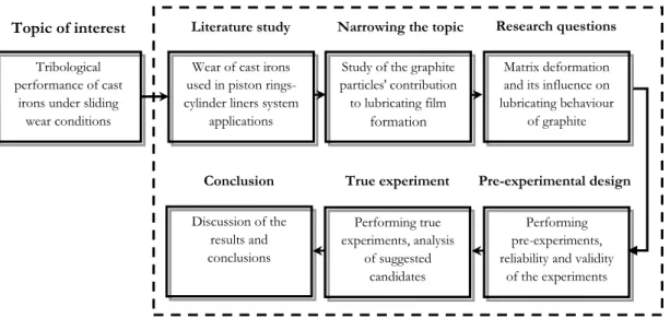
As Figure 10 illustrates, the research process in this thesis has been largely structured in accordance with deductive reasoning, similarly as described by Williamson [119]. The present study began with the establishing of the topic of interest towards the investigation of cast iron′s self-lubricating performance so as to fulfil both the criteria of industry-applicable research and scientific areas. Hence, the research effort has been driven by a desire to investigate the tribological and mechanical properties of cast iron piston ring–cylinder liner systems in diesel engine components. In the first stage, the influence of graphite particles on the self-lubricating behaviour of cast iron materials was studied.
Figure 10. Visualisation of the relationship between the research approaches, studies, and strategies′ phases.
The gathering together of the relevant information was performed in order to understand cast iron piston ring action under sliding conditions, and to develop proper experimental methods. A literature review was undertaken with the central goal of investigating the wear behaviour of cast iron and the effects of graphite particles on tribological performance, and was carried out in accordance with the information-gathering process described by Rumsey [120]. The resources used were online databases (mainly Primo, Metadex, ScienceDirect, Scopus, and SpringerLink). After performing the pre-experiments and evaluating the results (reliability and validity), the real experiment was conducted, and the results obtained were evaluated, analysed, and compared. A conclusion was derived, based on the relationships between the results achieved and outcomes from prior research.
Tribological performance of cast
irons under sliding wear conditions
Wear of cast irons used in piston rings-cylinder liners system
applications
Study of the graphite particles′ contribution to lubricating film formation Performing true experiments, analysis of suggested candidates Matrix deformation and its influence on lubricating behaviour of graphite Discussion of the results and conclusions Performing pre-experiments, reliability and validity
of the experiments
Topic of interest Literature study Narrowing the topic Research questions
True experiment Pre-experimental design Conclusion
![Figure 4. Schematic illustration of abrasive wear modes (introduced by Zum-Gahr [30]) embedded in deformation modes as a consequence of plastic deformation (theoretically](https://thumb-eu.123doks.com/thumbv2/5dokorg/4661352.121455/18.892.192.627.647.974/schematic-illustration-abrasive-introduced-deformation-consequence-deformation-theoretically.webp)
![Figure 7. Nucleation of lamellar graphite on (a) SiO 2 formed by heterogeneous catalysis of CaO, Al 2 O 3 and oxides of the alkaline metals (proposed by Weis [64]), (b) three-stage model](https://thumb-eu.123doks.com/thumbv2/5dokorg/4661352.121455/20.892.103.713.784.947/figure-nucleation-lamellar-graphite-heterogeneous-catalysis-alkaline-proposed.webp)
![Figure 12. A schematic representation of the method used for determining the degree of orientation of graphite lamellas; the sliding direction is set as a reference axis [103]](https://thumb-eu.123doks.com/thumbv2/5dokorg/4661352.121455/34.892.301.546.648.924/schematic-representation-determining-orientation-graphite-lamellas-direction-reference.webp)
