School of Innovation, Design and Engineering
MASTER THESIS IN
SOFTWARE ENGINEERING-GSEEM
(GLOBAL SOFTWARE ENGINEERING
EUROPEAN MASTER)
Design Philosophy for User
Friendly Parameter Handler
ii
ABSTRACT
Date: 15 November 2012Carried out at: Bombardier Transportation Sweden AB Advisor at MDH: Radu Dobrin
Advisors at Bombardier: Niclas Evestedt and Erik Simonson Examinator: Ivica Crnković, and Henry Muccini
DCU2 (Drive Control Unit 2) is an important control system used in applications for train systems that are configured by a set of parameters. Traditionally, parameterization is conducted by using an excel workbook during the software development. The parameters are set up and further export the parameters to the compilation step. Such approach has a number of disadvantages, e.g., delays on the validation and verification steps, system configuration overhead, and suboptimal system reliability generated by the parameter configurations.
To improve the parameterization process, this thesis implements a model-based software architecture approach and automotive industry standards via rapid prototyping by using scrum methodology. We do this by using Matlab/Simulink, TDL (Time Description Language) and UML (Unified Modeling Language) architectural description languages to enable different views of the software architecture. We then develop different prototypes that implement ASAM (Association for Standardization of Automation and Measuring Systems) standards like XCP protocol over Ethernet (code ASAM MCD-1 XCP V1.1.0) and ASAP2 (code ASAM MCD-2 MC) in every scrum sprint. An evaluation then shows that the thesis successfully implements previously defined standards that use commercial tools from e.g., Vector, proving that the parameter’s unit control can be handled via online calibration and measurement, leading to a significant improvement in Bombardier’s software development process in a distributed development environment.
Keywords: Drive Unit Control, Engine Unit Control, ASAM, online calibration and measurement, model based development.
FÖRORD / PREFACE
This master thesis was provided by Bombardier Transportation Sweden AB and conducted at Mälardalen University in the school of Innovation, Design and Engineering.
First of at all, I would like to express my gratitude to have the opportunity to do my master thesis at Bombardier Transportation Sweden AB since. I strongly believe that the time that I have spent into PPC/ TESEC Control Product department as a thesis worker has significantly enhanced my personal and professional background. I would like also to express my sincere appreciation to my supervisor, Niclas Evestedt and department’s manager Erik Simonson from Bombardier Transportation, for their consistent follow up, valuable feedback, smooth guidance and encouragements to achieve the desired results and project milestones. I would like to extend my gratitude to my colleagues from Bombardier Transportation Max Johansson, Björn H. Andersson, Martin Torelm and Bjarne Jensen, and from Vector Informatik Andreas Patzer, Christoph Heller and Wojciech Przystas, for their valuable technical support during this project development
I also feel appreciated for the support I got from my university’s supervisor Dr. Radu Dobrin. His work has greatly favoured my thesis development by a good combination of academic research feedbacks and service development inputs for committing the goals that this thesis pursues to obtain. I would also like to give special acknowledgements to my program‘s coordinators and thesis examinators Dr. Henry Muccini and Dr. Ivica Crnković for their valuable guidance during my study time in University of L’aquila (Italy) and Mälardalen University (Sweden) respectively, and for providing me the opportunity to join Global Software Engineering European Master program as well .
Finally, I would like thank God and to appreciate my father, my mother, my sister my boyfriend and my friends for their constant support on achieving my professional and personal goals during my Master’s studies.
CONVENTIONS
Acronym MeaningDCU2 Drive Control Unit 2
ASAM Association for Standardization of Automation and Measuring Systems ECU Engine Control Unit
CTO Command Transfer Object DTO Data Transfer Object DAQ Data Acquisition List STIM Data Stimulation List
SiL Software in Loop
HiL Hardware in Loop
SUT Test Benches
LET Logical Execution Time TDL Timing Definition Languages
XCP ASAM standard protocol for calibration and measurement
DTS Data Set
IDTS Integrated Data Set
AC Alternate Current
DC Discrete Current
DLL Dynamic Link Library RTOS Real Time Operating System
CONTENTS
Kapitel / Chapter 1 INTRODUCTION 7
1.1 ... Background ... 7 1.2 ... Purpose ... 7 1.3 ... Problem Formulation ... 8 1.4 ... Justification ... 8 1.5 ... Delimitation ... 9 1.6 ... Thesis Contributions ... 10
Kapitel / Chapter 2 RELATED WORK 11 2.1 ... Academic Related Work ... 11
Model Based Development of Automotive Control Systems ... 11
Architectural Description Languages for Real Time Systems ... 12
Validation and Verification of Automotive Control Systems and model based testing ... 12
2.2 .. Commercial Standards ... 13
Basic Definitions ... 13
ASAM Standards ... 13
Calibration Tools common architecture ...14
XCP Protocol ...14
Transport layer over Ethernet ... 16
DAQ-List- Data Acquisition Lists ... 16
STIM-Lists- Data Stimulation Lists ... 17
Event Channel Module: ... 18
2.3 .. Thesis Approach ... 18
Kapitel / Chapter 3 MODEL/METHOD 19 3.1 ... Research Protocol Definition ... 19
Research Strategy ... 19
Research Keywords ... 20
3.2 .. Software Development Methodology ... 20
Agile ... 21
Scrum ... 21
Scrum roles ... 21
Scrum Steps ... 22
Related concepts: ... 22
3.3... Assumptions and Limitations Concerning to the Thesis Development ... 23
Environmental ... 23
Technologies ... 23
Work Distribution ... 24
Time and location ... 24
Prototyping ... 24
Initial Costs ... 25
Quality Assurance Plan ... 26
Risks ... 26
Kapitel / Chapter 4 SOLUTION 28 4.1 ... Commercial Tools ... 28
Vector: ... 28
CANape in model based development by using Matlab/Simulink: ... 28
eASEE: ... 30
ASAP2 Editor:... 30
ETAS: ... 30
INCA base product: ... 30
dSPACE: ... 30
Control Desk Next Generation: ... 30
Variable Editor: ... 31
4.2 .. Commercial Tool´s Solution Selection ... 31
Motivation for Tool Selection ... 31
Evaluation of the Commercial Tools for Parameterization ... 32
CANape, eASEE from Vector ... 32
INCA from ETAS ... 33
Control Desk Next Generation (CDNG) from dSPACE ... 33
4.3 .. General Design Description of Developing Prototypes ... 34
4.4 .. Use Cases organization per prototype ... 37
4.5 ... State Machine Description ... 40
4.6 .. Design Decisions ... 41
Concern: Which method shall we use for checking memory and resource availability? ... 42
Criteria: Functions developed in operative system, complexity, time effort. ... 42
Concern: Which persistent memory must we use for storing parameters when DCU2 is off or disconnected? ... 42
Criteria: security, maximum memory storage capacity, back up resources, memory space availability, and memory overload risk. ... 42
Discussion about requirements fulfilment during XCP-Train Device Integration ... 43
Kapitel / Chapter 5 RESULTS/EVALUATION 46 5.1 ... Results discussion of different prototypes ... 46
5.2 ... Recommendations ... 58
Kapitel / Chapter 6 CONCLUSIONS AND FUTURE WORK 60
Kapitel / Chapter 7 REFERENCES 61
APPENDIX A-RISK MATRIX 63
APPENDIX B - SOFTWARE ARCHITECTURE DOCUMENT 70
Kapitel / Chapter 1
INTRODUCTION
1.1 Background
DCU2 is an important control system used in several applications for train systems, and it is configured according to the system requirements and characteristics during software development and maintenance processes. The set of train applications is configured before compiling and downloading software to the DCU2 controller. A commonly used process in this step is saving this configuration into an excel workbook which allows to set up and export the parameters in the compilation step. However, this mechanism represents a drawback for the software integration process since it cause delays, overhead in configuring controllers due to the lack of documentation, lack of expertise, reliability at the data generated for enabling a good system performance, etc.
In addition, one of the inconveniences that causes delays is that the excel file takes a large amount of time to be opened since its size is extremely large. Another disadvantage is that there are sets of critical parameters’ value that fulfil safety critical properties that have certain dependencies among them that are not validated. Hence, this introduces several dependency conflicts during DCU2 configuration process. Consequently, this can cause unexpected results during the testing phase because a set of parameters is not valid, or are set up with an inaccurate value. Furthermore, the excel workbook is not user friendly, and it does not have a help site either. As the consequence, this adds unnecessary complexity during software development.
1.2 Purpose
The purpose of this thesis is to solve the previous explained situation by designing a new philosophy to manage train controller parameters based on a model-based architecture that implements commercial tools via fast prototyping. Thus, we will perform a scientific review about commercial tools, trends, and techniques that might offer a set of solutions and functionalities to solve the previously mentioned situation. This review also analyses to determine tool’s advantages, disadvantages, and business feasibility. This provide necessary inputs to us for purposing benchmarking solutions, project scope, contacting suppliers for commercial tools, and resources. In addition, we will describe a formal architecture and design a new parameter handling philosophy to be integrated with commercial tools into the DCU2. The thesis also develops some prototypes to check whether proposed design and the tool fulfil the system requirements. Proposed prototypes will contain solutions in high level and low level to handle parameters in DCU2. The thesis objectives are:
• Perform a systematic research about calibration tools, handling parameter techniques, and automation calibration tools.
• Analyze results to propose best solutions based on benchmarking. • Discuss research results.
• Design software architecture and parameter classification to adapt commercial tools into current situation.
• Develop prototypes to perform validation and verification from proposed architecture.
1.3 Problem Formulation
The main problem that Bombardier has to face every time that DCU2 parameterization is performed is having project delays, lack of parameter traceability and configuration management. Software developers and application engineers have to overwork the process because they have to run the whole configuration process every time that a single parameter is changed. This is due to the lack of parameter traceability that the current tool lacks. Therefore, we will study the following research question;
“How to implement a new philosophy for handling parameters that allows engineers to handle distributed development by decreasing redundancy and providing team collaboration, controlled versioning, configuration management and a life cycle management at Bombardier Transportation?” .
In order to answer this research question, we will perform a scientific review based on scientific and industrial papers, articles, and related automotive industry’s standards. This will provide us the necessary background in order to state a feasible solution. Afterwards, we will design and model a software architecture that implements the suggested solution and validate it via fast prototyping. Hence, we have divided the main research question as follows:
• Which commercial tools exist for handling parameters in the automotive industry? How good are those for our purposes?
• Which are new trends and standards for optimizing controllers’ parameter configuration?
• Which are technical and functional details about parameter calibration commercial tools?
• Which are the software design patterns and model based techniques that can help us to design the new parameter handling philosophy?
• How should we develop the different prototypes for validating and verifying the purposed philosophy?
1.4 Justification
Nowadays, Bombardier Transportation is looking for a set of tools, methodologies, process and others useful ways to increase productivity in their product development. Thus, PPC/TESEC Control Product department has identified a critical process that has been generating delays at every DCU2 product development project. In particular, a current excel workbook that handles parameters causes much overwork at any project development processes such as software testing, and software validation and verification. This is because the developers have to spend much time and effort to execute manual tests for every single parameter several times
Hence, we shall design a new independent, scalable, reliable philosophy in order to end up with a feasible solution to cope with the described inconvenient. As we will implement a new tool, delays in project development, lack of parameters’ reliability, overwork during
software development and configuration will be significantly reduced. Consequently, this philosophy will improve project metrics, productivity during product development. Additionally, the new philosophy will enhance main Bombardier’s goal about competing in the market with new tendencies in software development.
In addition, this thesis provides an internal value that is related to compete with other companies in providing safe and reliable products to generate great revenue for the organization. Regarding to productivity increment, we will provide a solution for handling parameters that will save time and overhead in projects at PPC/TESEC Control Products department, by enhancing team collaboration and distributed development. Thus, we will provide a more efficient process workflow to get results on time. In addition, the thesis presents an external value that will be beneficial to other departments at Bombardier to deliver more reliable configuration references for further projects in a short amount of time. This will bring beneficial results at company’s metrics by reducing costs and time effort.
1.5 Delimitation
This thesis will require some services and materials in order to develop a new and complete parameter handling philosophy. Mälardalen University (MDH) and Bombardier Transportation will provide most of services in a close collaboration among them. MDH will offer a thesis worker who will perform the research an academic supervisor. Bombardier Transportation will provide all physical and economical resources to design and develop the philosophy. In particular, PPC/TESEC control products department will provide industrial supervision to collaborate with the technical knowledge and the voice of the customer. We will require some materials during the thesis development that refers to hardware and software pre-requisites and procurement process. In this case, PPC/TESEC department will request to IT division some materials like application server, database server, personal computers, developing and testing environments, modelling tools, development IDE and IT support. Furthermore, Bombardier‘s administration department will handle all procurement process required to get these materials. Furthermore, we will not consider a set of software development activities to be executed due to the thesis time limitations. Thus, a list that explains every excluded activity it is stated below:
• Testing: we do not include testing activities since they are time consuming, and they might represent an obstacle for developing the prototypes. Thus, validation and verification steps will be performed in order to check system functionality and the architecture. Therefore, Bombardier’s staff may perform testing activities in case they decide to implement the solution.
• Implementation: due to the nature of a safety critical system, we consider that it is difficult to run full implementation of commercial products in Bombardier in a short time without considering testing phases and the IT infrastructure support. • Pilot programs: they are considered as a future work only if Bombardier decides
to implement the solution.
• Work overflow design: we will consider this step an assumption provided by a supplier because it might introduce several changes into Bombardier´s
organization that represent an impact into any project lifecycle.
• Parameters classification: This suggests including a deep study into all possible options for classifying parameters that is time consuming. Therefore, this point may be subject to a further work. Instead, we will provide constrains and rules to adapt existing parameters into different commercial tools by showing some project examples.
1.6 Thesis Contributions
In short, the following list outlines the major contributions of this thesis:
• Scientific review and literature survey concerning tools for parameterization in the automotive industry
• Analysis and evaluation of the commercial tools for parameterization process at Bombardier
• Justification of the tool selection, methodology and standards for the new parameter handler philosophy
• Implementation of standards and commercial tools by developing prototypes • Evaluation of the thesis results
Kapitel / Chapter 2
RELATED WORK
2.1 Academic Related Work
Model Based Development of Automotive Control Systems
Nowadays, the usage of distributed architectures in real time automotive control systems significantly reduces costs and maintenance activities [1]. This approach can be obtained through automating different software development processes according to different engineering domains. In particular, flexible and comprehensible modular systems can be designed and developed via model-based architecture in order to achieve flexible, reusable, function oriented and scalable software components. Thus, some paradigms that have been currently used among different automotive industries include system orientation, functional orientation, and systems engineering. System orientation refers to develop a system integration based on components architectures. In contrast, functional orientation describes a systematic requirement engineering and architecture/function development based on feature modeling. Likewise, system engineering makes emphasis on requirement management, architecture, and integration phases. Furthermore, there is the need of describing different architectural viewpoints that shall be composed of conceptual and technical views. Conceptual view states hierarchical functional views about local subsystems interaction whereas technical view describes code architecture and runtime behaviour.
It has been claimed that using model driven design methods may enhance different modeling tasks [2]. One idea is to develop macroscopic and microscopic models. The concept about macroscopic model suggests to generate some graphical or textual models that can represent control software behaviour, algorithms and parameter descriptions to run a simulation based on these models. Microscopic models describes a generated code via model to model transformation that represent a description about low level components and their different connections that allows parameters, signals and values passing as shown in Figure 1.
Figure 1: A classical transformation model in the field of model driven engineering
Architectural Description Languages for Real Time Systems
Modern approaches to software design like model driven engineering (MDE) provides different solutions to provide timing properties preservation in real time systems from high level models to low level models [1, 25]. Some synchronous languages such Logical Execution Time (LET) and Timing Definition Languages (TDL) describe different real time system timing properties. In particular, there is a commercial tool suitable to design graphical and textual models like VisualCreatorTDL tool for TDL. Then, this tool provides integration with Matlab/Simulink where other models can be generated via model-to-model transformation tool options.
Validation and Verification of Automotive Control Systems and model based testing
Some approaches have been using recently to run validation verification at automotive control systems [1]. One is software in the loop (SiL) and another is hardware in loop (HiL). HiL enhances simulations by configuring a hardware environment to check whether a functional or timing property is satisfied, whereas, SiL is mainly used for checking software functional properties. In Addition, there are other important testing types that are used as model based testing and mutation testing. Model based testing requires a test infrastructure that involves under test (SUT). This requires a HW/SW support from test bench that may include HiL or SiL. In contrast, mutation testing quantifies a test suit by measuring how many faults can a mutant version from original software may fail that represent common programmer´s typing mistakes at the code. Consequently, all of previous mentioned approaches are designed and executed by Matlab/Simulink, dSpace tools, or other resources.
2.2 Commercial Standards
In this section, we will describe some basic definitions used in commercial tools and standards in the automotive industry. We will give the detailed information as follows: Basic Definitions
This section will outline some basic terms that current commercial tools uses to apply different approaches based on section 2.1 in automotive control system software development [3]. The terms belong to “Measuring and Calibrating” process at controllers’ development at V-Model in the right side (validation and verification steps) as it is shown in Figure 2.
Figure 2: Development of an ECU (V-Model)
• Calibration: it is a term that describes different requirements to perform measuring, adjusting parameter/signal values, flash programming, and other related tasks in a rapid prototyping environment.
• Measuring: this is a technique that it is used to visualize control algorithm´s behaviour, record and display I/O parameters, environmental data, internal variables, etc. This also shows different time-correlated possible variables that can be considered in offline or online evaluation.
• Calibrating: it is a process that optimize closed loop controlled system´s behaviour to determine whether a parameter or records affect control system process. This task is usually performed by the application engineers according to project requirement and specifications.
• Flash Programming: this kind of program style calibrates ECU or other controller’s parameters by reprogramming it flash memory.
ASAM Standards
ASAM is for short Association for Standardization of Automation and Measuring Systems that provides different solutions to provide efficient and professional project management [4]. The association develops different standards and protocols to assist automotive industries to develop their controller products. Some interfaces that ASAM includes are described below:
measurement device. This connection is handled via transportation layer. This also includes interfaces for managing internal run-time variables and calibration parameters..In particular, XCP protocol is defined in this layer.
• ASAM MCD-2: [3, 4] this states a set of standards for ECU access and network data transmission that are enabled through some file exchange conventions like ASAP2 or ASAP3. Besides, file descriptions contains memory address, data type, data format and some conversion functions to transform internal parameter to physical parameters.
• ASAM MCD-3: [3, 4] this standard states and object-oriented API between measurement, calibration and diagnostics functions. Therefore, this allows having test automation in client server systems between controllers, PC or other supplier. It also suggests different solutions to run measurement and calibration process in a high-level automation system in order to acquire measurement data and
perform parameter calibration.
• A2L file: [4] it is a description format for parameters and measurements of an Electronic Control Unit that also describes communication and interface
descriptions. This kind of file also contains the required information to transform internal data into physical one and vice versa. A common market name is ASAP2 or ASAP3 (that refers a newer version for standard ASAM MCD-3).
Calibration Tools common architecture
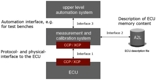
A common ASAM architecture [5, 16] defines communication between measurement and calibration systems and ECU. It also provides a set of interfaces that allows communications between automation interfaces for test benches, protocol and transport layers. This set of interfaces communicates directly to A2L description file of the memory content. This can be shown in Figure 3.
Figure 3: ASAM Interface model XCP Protocol
XCP protocol [7, 17, and 16] refers to “Universal Measurement and Calibration Protocol”. It serves to enable different interfaces in a measurement and calibration system. It also allows communication over other standard protocols like CAN, Ethernet, USB, etc. This protocol is defined as two-layer protocol since it separates protocol layer from transport
layer, and it takes Single-Master/Multi-Slave communication style. Thus, a single master system describes the connection between PC to multiple slaves that run in embedded systems via request and response messages passing as it is described in Figures 4 and 5. This allows getting a complete view of any automotive control system where this protocol is executed. This mechanism provides the flashing programming feature since it allows modification of persistent memory to be replaced by a firmware or calibration parameters. This means that the master can perform a complete replacement of the code that runs in ECU via firmware once this has been uploaded. This feature prevents boot loader component at ECU, so XCP master may have a complete control over ECU during calibration tasks. Moreover, XCP can be protected with a Seed and Key architecture that prevents control units from tampering and password sniffing over transport layer.
Figure 4: XCP Topology
In particular, message passing between master and slave contains distinctions to handle different commands [6, 17]. Thus, an important distinction is made between Command Transfer object (CTO) and Data Transfer Object (DTO) to handle a synchronous data acquisition from slave’s memory. CTO contains the following commands: CMD (command), RES (Response), ERR (Error), EV (Event), and SERV (Service Request Processor). In order to get required data from slave, DAQ (Data Acquisition) and STIM (Stimulation) commands are executed to transfer objects from event-driven reading of measurement variables. This structure is described in Figure 6.
Figure 6: CTO and DTO structure on XCP Transport layer over Ethernet
XCP over Ethernet [7, 17] message frame is done through packets. This is composed of a header and a tail. XCP header contains packet number and length values whereas XCP packet is composed of data information such as DAQ, TIMESTAMP, etc as it is explained in Figure 7. This allows to TCP/IP protocol to impose a limitation of packet size where DTO/CTO is described to enhance network performance.
Figure 7: Header and Tail for XCP over Ethernet. DAQ-List- Data Acquisition Lists
A DAQ list [7, 17] allows sending a large amount of data in a short period with low bandwidth. Each data list contains a number of Object Descriptor Tables (ODTs) and Object Descriptor Table Entries (ODT Entries). ODT contains address and length from parameter
description. When DAQ-list is processed, each list data is copied into the corresponding address from each ODT as it is stated in Figures 8 and 9. The list may contain static and dynamic configuration. Static configuration may be used when parameter descriptions shall not be modified. In contrast, Dynamic configuration can be used during calibration task since
the master can have a direct access to change parameter descriptions.
Figure 8: DAQ- ODT list number identification (PID)
Figure 9: DAQ-list memory allocation STIM-Lists- Data Stimulation Lists
STIM-lists [7, 17] have similar DAQ’s-list features, but they allow master to stimulate data in a controlled environment. This is because master can write its last buffered data in the slave until STIM list is executed. This permits to get a data copy into a specific ECU memory address. Consequently, this avoids the need of implementing control loops mechanism by decreasing redundancy.
Event Channel Module:
In order to handle events, XCP provides an event channel module [8, 17]. This permits to DAQ list to be simultaneously active to trigger events at the slave component. When an event have to be triggered, this channel build a generic signal source that allows to determine whether a data may be transferred simultaneously or not in a given period. This channel also describes frequency of event execution.
2.3 Thesis Approach
We will implement a theoretical framework based on different software architecture approaches and automotive industry standards in order to arrive into a feasible solution. In this sense, we will use some approaches from model-based development of control systems for designing a solution based on different architectural representations. Then, some basic concepts from model driven engineering will be used to generate code in order to run validation and verification process via Matlab/Simulink and TDL languages. This is for generating a close simulation to real-time behaviour. Therefore, we can use a model checking approach for checking whether state machines that handle previous behaviour may meet safety critical properties. In addition, we will implement ASAM standards for developing a set of prototypes since they have been implemented successfully in other automotive industries to solve related issues and challenges.
Kapitel / Chapter 3
MODEL/METHOD
3.1 Research Protocol Definition
In this section, we will define the strategy to perform a scientific and industrial review for finding empirical evidence to the research questions outlined below. This strategy describes the data extraction techniques to assure that the extracted information will be relevant to the research questions.
Research Strategy
We will use an industrial oriented research strategy. We will also use different kinds of resources, libraries, and keywords from stakeholder references. The research libraries that we will use are Science Direct, SpringerLink, ASAM download center, IEEE libraries, Google scholar or web, automotive magazines, supplier’s product download center, etc. Moreover, we will use sources and references from stakeholder’s suggestions, and supplier´s contact information. Other useful resources are located at Bombardier´s knowledge database that can provide enough documentation about DCU2, train systems and other related devices. Furthermore, we are expected to run two research iterations in order to gather preliminary results and refine keywords to filter results respectfully. Additionally, we will run a set of interviews with the related stakeholders in PPC/TESE as a complement of the collected information to understand the current situation and system requirements. In this sense, some questions that we will answer in this research are:
• Which are commercial tools for handling parameters in automotive industry? Are there any commercial tools that can offer solutions to calibrate parameters in automotive industry? How good are those for our purposes?
• Which are current study cases that claim benefits of using these commercial tools? • Which are new trends about optimizing controllers’ parameter configuration? • Which are technical and functional details about parameter calibration
commercial tools?
In addition, we have considered different techniques as a data extraction strategy from the scientific and industrial review to optimize research time, analysis, and the thesis discussion. This will allow us to filter keywords and refining the review results. Some of them are:
• Read abstracts and other general overview at each found article to determine whether it is useful or not.
• Highlight keywords and main ideas from articles.
• Make a contact list about stakeholders, suppliers, and other key people interested in project.
• Save the minutes of meetings (MoM) into a document to organize and analyse stakeholder references and suggestions.
• Review at Bombardier´s document references to reach more information about their products.
• Extract resources according to publication date and location. This will help us to determine whether the article presents a proved theory or not. Thus, if the article presents a non-proved theory, we will only extract a key idea or basic concept. Otherwise, we will consider further information such as solution details, use cases and other useful information.
Research Keywords
• ECU Calibration Tool • ECU Calibration optimizer • ECU Calibration parameter • DCU2
• Train propulsion systems • ASAP2 file • ASAP3 file • ASAM MDC-3 V2.2.0 • ASAM MDC-2 MC • XCP Protocol • Automation calibration • MCU Signals Parameters • Calibration tool architecture
• Calibration tool requirements/ pre requisites • Automotive software parameter configuration • Automotive software calibration Tool
• CANape • INCA • dSpace • CalDesk
• ControlDesk Next Generation (CDNG) • ASAM AE Standards
• VxWorks
• PowerPC hardware Architecture
3.2 Software Development Methodology
In order to develop a solution that solves the research question, we have selected a set of approaches from the section 2.1 and the agile methodology with the Scrum method. One of the selected approaches refers to model based development in the automotive industry that we will use for designing the software architecture. Then, we will validate and verify the architecture by applying model checking techniques, model simulation, and fast prototyping based on SiL and HiL as we have described them into the section 2.1. We will also use the described techniques for executing and verifying the DCU2 parameterization process. Therefore, we will apply an iterative and incremental methodology such Agile based on Scrum methods to allow us to develop the different prototypes that will implement the previous selected approaches. Thus, we have stated brief description about Agile and Scrum
above:
Agile
Agile software development [14] is a group of software development methods based on iterative and incremental development, where requirements and solutions evolve through collaboration between self-organizing, cross-functional teams. It promotes adaptive planning, evolutionary development, and delivery, a time-boxed iterative approach, and encourages rapid and flexible response to change. A conceptual framework promotes foreseen interactions throughout the development cycle. Furthermore, it is very effective where Client frequently changes his requirement because it involves more client interaction and testing effort. This ensures bugs are caught and eliminated in the development cycle, and the product is double tested again after the first bug elimination. Another Agile method’s advantage is that it allows for specification changes as per end-users requirements, spelling customer satisfaction. Hence, there are two methods by which this methodology can be implemented as scrum and extreme are programming. Consequently, we have selected scrum methodology for developing this thesis and we describe it as following:
Scrum
Scrum [15] is an iterative and incremental agile software development method for managing software projects and product or application development. This is composed of roles, project lifecycle, release, and sprints. Some of these concepts are described below:
Scrum roles
Scrum [15] is a process skeleton that contains sets of practices and predefined roles. The main roles in Scrum are Product owner, Scrum Master, and Team Member that are described below:
• Product Owner: The Product Owner represents the voice of the customer and is accountable for ensuring that the Team delivers value to the business.
• Team Member: a Team member is any person that belongs to the development team that is responsible for delivering any product or artefact. • Scrum Master: Scrum is facilitated by a Scrum Master, also written as Scrum
Master, who is accountable for removing impediments to the ability of the team to deliver the sprint goal/deliverables. The Scrum Master ensures that the Scrum process is used as intended. The Scrum Master is the enforcer of rules. A key part of the Scrum Master’s role is to protect the team and keep them focused on the tasks.
Figure 10: Scrum Steps Scrum Steps
An important feature from the iterative process is that it contains sequential steps and a lifecycle that ensures goal commitment [15]. This is shown in figure 10, and some of these steps are:
• A product owner creates a prioritized wish list called a product backlog. • During sprint planning, the team pulls a small chunk from the top of that wish
list, a sprint backlog, and decides how to implement those pieces.
• The team has a certain amount of time, a sprint, to complete its work - usually two to four weeks – but they meet each day to assess its progress (daily scrum), which we will do according to our needs and time
• Along the way, the Scrum Master keeps the team focused on its goal. • At the end of the sprint, work will be presented on our milestones as a final
product for that phase
• The sprint ends with a sprint review and retrospective on which all project members will discuss what has been done, and what has not
• As the next sprint begins, the team chooses another chunk of the product backlog and begins working again
• The cycle repeats until enough items in the product backlog have been completed, or a deadline arrives. Which of these milestones marks the end of the work is entirely specific to the project, but in our case, goal is to provide solutions to every requirement. No matter which impetus stops work, Scrum ensures that the most valuable work has been completed when the project ends.
Related concepts:
• Product backlog: [15] may be dynamic where Items may be deleted or added at any time during the project. It can also get prioritized items with the highest priority are completed first. Therefore, it will be progressively refined where Lower priority items are intentionally coarse-grained.
• Sprint backlog: [15] a sprint backlog is a negotiated set of items from the product backlog that a team commits to complete during the time box of a sprint. Items in the sprint backlog are broken into detailed tasks for the team members to complete. The team works collaboratively to complete the items in the sprint backlog, meeting each day (during a daily scrum) to share struggles and progress and update the sprint backlog and burn down chart accordingly.
• Potentially Shippable: [15] after every sprint product is considered potentially shippable. In that phase, one part of the project is considered done no matter which requirements are met since we will not have time to consider reviewing them. There is a possibility that couple of requirements will be used in two different sprints. This is not very popular among Scrum process at all, but we would like to ensure ourselves to have a back door if something goes wrong in one sprint. The product owner makes the decision about when there will be a release of any functionality or deliverable.
3.3 Assumptions and Limitations Concerning to the Thesis Development
Environmental
We will develop this project in three different servers that will stay physically between 2 computers. This schema allows developing fast prototypes regardless procurement time limitations. Thus, a computer may contain two servers: one for developing database and other for configuring application database and configuration management. The other computer may serve as client for application server environment and as virtual server for handling Scrum management tool (Ice Scrum). Besides, we will get a DCU2 sample board to test low-level solutions. Once that prototypes have been finished and validation and verification steps have been completed, project sponsor may decide about running the implementation to request all needed hardware.
Technologies
We will organize this project according to different solutions that implement a combination of system styles. One solution suggests implementing a client server application to manage parameter calibration. Other solution will be based on real time systems event handling that is composed of a layered architecture that describes different protocols and standards in automotive control systems. In this sense, prototypes from both scenarios will be designed, developed and tested by following some model-based architecture, component based architecture and rapid prototyping concepts. Therefore, validation and verification steps will be performed in conjunction with some stakeholders and application engineers. Consequently, some technologies that may be accurate to use to cover different approaches are listed below:
• Developing Languages: o Java Standard Edition o C/C++
o Matlab/Simulink
• Architectural Description languages: o UML o Matlab/Simulink o TDL • Development IDE: o Matlab/Simulink o Mitrac Tools • Modeling tools: o Magic Draw
o Matlab/Simulink o TDL Visual Creator • Solutions from market:
o Control Desk Next Generation (CDNG) o CANape 10.0 o INCA tools o ASAM standards o eASEE Tool o IceScrum • Servers:
o Apache Tomcat for an application server o Oracle
• Database: o Oracle
Work Distribution
Since we will implement in this project different software and hardware components that will follow rapid prototyping concepts, it is important to take as a sample a previous project, select a device and team responsibility to perform all different tasks during project development. This means that we will use Scrum method to distribute some punctual task among team members and execute them in parallel or in a sequential way. Hence, periodical task will be assigned and distributed at every sprint according to the corresponding goal. Some task can be shared between suppliers and thesis worker under close collaboration, but they are mutually exclusive. Furthermore, we will execute validation and verification steps between the thesis worker and the selected team engineer or application engineer by giving mutual collaboration to avoid unnecessary time consuming from both parts.
Time and location
A master thesis worker at PPC/TESEC Control products department at Bombardier will develop this thesis. This will be developed under close cooperation and collaboration from the IDT department in Mälardalen University at Vasteras, Sweden. Furthermore, we will develop the thesis in 5 months where we have included validation and verification steps. Then, we have distributed prototyping workload to deliver several prototypes from May 2012 to August 2012. However, there is a burning issue related to procurement process and staff availability because it may delay some important activities related to gather software, requirements, documentation and other related resources or services. Thus, we shall fully follow the Scrum method in order to accomplish each sprint goal. Another assumption is that the master thesis worker expects to work 40 hours per week that includes meetings, courses, mentoring and reporting time. Besides, we also have considered holidays from April to August that may affect on the thesis planning.
Prototyping
In order to develop and deliver every prototype, we will organize the different activities according to the Scrum method. Thus, we have planned to deliver two releases with two sprints each in order to deliver four prototypes. This means that we have planned one release for the solution design and validation and another release for developing run-time prototypes.
In addition, we need to select a finished project, device, and stakeholders. Then, we can select a set of use cases and scenarios to narrow prototype functionalities and development activities according to the Scrum Method. This allows us to have a close collaboration and mentoring between the staff and thesis worker. In this sense, we will develop an initial prototype based on a model to validate concepts and design. Then, a low-level initial prototype will prove the possibility to change parameter values in running application process. This is followed by the packages transmission XCP over Ethernet at the DCU2 to check XCP feasibility. Finally, we will build client server calibration tool prototypes to prove the overall concept between calibration tools and DCU2. Therefore, we have described each prototype as follows: Prototype No. Release No. Title Sprint No. Description 1 1 Model Simulation
1 A model will be designed to simulate XCP over Ethernet at DCU. This model will be composed of a behavioural description to be designed and simulated in Matlab/Simulink and TDL VisualCreator, and a state machine that contains XCP states to check properties via Model Checking techniques through UPPAAL tool.
2
Memory Page exchanging
2 Build a C script that will handle memory page exchange via XCP protocol layer functions to allow dynamical parameter changes based on few amount of parameters.
3
2 Client Server Scenario
3 A scenario to handle parameters via Vector tools will be developed to check workflow process. This will check responsibilities and roles management in a distributed team as well.
4
XCP/DCU2 Scenario
4 A scenario will be loaded at DCU2 to handle signals and few parameters via XCP. This will represent using or selecting a parser provided by the supplier that generates an A2L from a selected small group of rules that DCU2 application contains for handling parameters or signals and files. Therefore, it will run a process to load signals based on A2L files Table 2: Prototype list definition
Initial Costs
Costs are low at the beginning of the thesis development because we can obtain evaluation licences to enables tool adaptation. Then, costs may increase significantly depending on number of floating licences, fixed licences, and different business cases that the implementation may require. Therefore, we consider that costs will be reconsidered and business cases will be re-formulated before implementing tool. In order to have an approximated cost for implementing any commercial tool in a given business case sample
scenario, we believe that it is possible to consider different licence quotations that each supplier has submitted as a reference.
Quality Assurance Plan
Since we will design and develop prototypes during this master thesis, we will execute validation and verification steps in different phases to prove different concepts. Thus, the idea is to run validation and verification based on models, prototypes, and run-time environment. During every phase of validation and verification, there will be continuously validation from customer and stakeholders to check whether requirements are fulfilled. Then, key activities where customers and stakeholders will be involved to run this plan are described below:
• Design software architecture to describe and detail high level and low-level representations.
• Build and execute simulations based on models described into the architecture to run validation and verification steps.
• Select small scenarios, functions, and properties to load them at different prototypes as a pre-requisite to get a run-time environment in a small scale. • Run prototypes in a real-time environment validation and verification in
conjunction with the customer and stakeholders.
• Implement model-checking techniques to prove via mathematical formal methods whether a property from the XCP protocol is satisfied. In Particular, a state machine that represents different XCP protocol events will be checked.
Consequently, we will design a behavioural and dynamic model in Matlab/Simulink to run different simulations based on a TDL model in TDLVisualCreator to check timing properties and protocol connections and interaction with the DCU2 application. Then, we will validate the protocol states through a state machine design via UPPAAL tool, which is a graphical model checker based on formal methods of validation and verification. Next, we will obtain DDL model via a C code generation from Matlab/Simulink process (Real-Time Workshop) to perform SiL activities according to each prototype’s needs. Besides, static descriptions will be designed in the software architecture in order to represent file, packages, layers and other software related components. After this, we will refine requirements and previous described architecture at each prototype sprint. Finally, requirement track will be updated continuously according to scrum plan and stories related.
Risks
Since this thesis requires that we handle several risks due to safety critical system nature, we will maintain traceability at every sprint between requirements, architecture, prototype, and risk plan. This traceability description will allow tracking most critical risks described in following subsections according to the risk management matrix. (See appendix A that describes a detailed risk matrix).
Safety critical/Security:
• Safety critical requirements were not properly defined, and product might not fulfil minimum safety critical properties.
• Improper safety critical function definition or design at tool may lead to Unit control critical failures.
Software Design/Technical:
• Inaccurate software design and development may lead into malfunction of any control unit component since XCP protocol permits a complete control over any
unit control.
Kapitel / Chapter 4
SOLUTION
According to what we have described in chapter two and three, we have selected the described methods and approaches for designing the solution that answer the research questions. This means that we will design a solution that implements ASAM standards such as XCP protocol and ASAP2, model based development techniques, and we will use commercial tools from the automotive industry. This will allow us to provide a solution that enhances team collaboration, control versioning, configuration management, and project life cycle management.
Therefore, we will describe in this chapter the commercial tools analysis, software design and its rationale for selecting the most convenient solution to each design concern. In addition, we will present and illustrate some important features from software architecture that we will design for implementing ASAM standards and commercial tools. We will also present a process workflow for handling the new philosophy and the system integration among protocols and tools.
4.1 Commercial Tools
Vector: CANape 10.0:
CANape [9] is a tool designed for optimizing and enhancing ECU calibration in an iterative process. This tool assists engineers to perform tasks like rapid prototyping, get test benches or test drives, run parameter calibration, measurement and diagnosis. In particular, there is a physical interface between CANape and the ECU via Ethernet, CAN, Flex Ray and XCP. This allows having online and offline calibration modes. With respect to measurement mode, it offers different views like graphical representation, DAQ list configuration, virtual signals, Matlab/Simulink models, and managing calibrated data. This tool also provides interfaces to handle A2L files, calibration, and data management systems (for instance, database and profiles management system in a client server application) via eASEE. Another supported feature is model-based development that allows transforming Simulink models into data analysis and measurement models. It also provides simulation and scripting mechanism to run, analyze, and verify models through DLL files or XCP server in Simulink. Furthermore, it provides the necessary framework to run software validation and verification, and model base testing in the parameterization process. Thus, an explanation about model based development by using CANape and Matlab/Simulink is at the following section:
CANape in model based development by using Matlab/Simulink:
CANape [3, 18, and 29] also contains some important features that enhance model-based development by using SIL approach. In particular, it is possible to simulate and perform
measurements and calibration tasks in a Simulink model by using an XCP server. This server and other required functionalities belong to a Matlab/Simulink library that is included in CANape via plugin installation. This plugin allows generating a DLL model in Matlab M-files, M-scripts, exporting options, and mapping model objects with A2L of any device in CANape. Then, it also permits adding XCP blocks into any Matlab model and generating A2L files as well. Then, it is possible to reuse them into the calibration and measurement process as it is in figure 11. Furthermore, CANape has the option for visualizing Matlab/Simulink model without executing the Matlab application. The model visualization allows having an iterative process during calibration and measurement activities without modifying controller´s code because only it updates the model independently from the code as it is in figure 12. Therefore, Real-time Workshop generates the corresponding code until this iterative process has reached the final version of the calibration data.
Figure 11: CANape-Simulink Model Interaction
Figure 12: CANape-Simulink general model based development flow
eASEE:
eASEE [10] is a client server application that provides functions for process support in complex calibration projects. The tool provides a schema that enhances collaboration among distributed teams by giving support for roles, responsibilities, and user authorizations. The schema allows handling parameter status, data management models, project documentation, reports and process workflow. Besides, it provides some functions for quality assurance, parameter validations, and A2L file modifications. This tool also contains a parameter editor that assists engineers to perform comparisons and merge data between parameter values and projects.
ASAP2 Editor:
ASAP2 Editor [9] is a product that provides a framework for generating A2L files out of Map files, and it is part of CANape functions. The ASAP2 Toolset performs file generation for ASAP2 standard and contains functions for creating, updating, merging, and comparing the generated A2L files. In particular, it is possible to create A2L files from C-code object files and manage address between A2L file and the system target. The editor contains an interpreter and a parser that handles object files and symbol tables according to the system target description.
ETAS:
INCA base product:
Similar to CANape 10.0, INCA [11] provides a framework for handling measurement and calibration systems. In particular, this tool contains a set of editors like hardware configuration, calibration scenario, variable selection, and memory page management that allows engineers to run the calibration/measurement configuration. Hardware Configuration Editor provides software based on a replication of the target hardware to run calibration and measurement tasks via experiment environment generation. Then, Calibration Scenario Editor describes set of calibration and references variables for setting parameters in a given calibration scenario. Thus, variable selection and experiment configuration editor define variables from different calibration scenarios. Furthermore, the Memory Page Management Editor is responsible for memory page and flash programming management to allow downloading/uploading and working with memory pages (for instance, reference page and working page). In addition, Calibration Data Manager and Measure Data Manager handle the data management from both calibration and measurement. Both managers allow generating local documentation, file exporting, and A2L file management.
dSPACE:
Control Desk Next Generation:
Control Desk Next Generation [12] is software that implements a philosophy to develop ECU software based on experiments that replicates ECU developing for rapid prototyping. This allows development teams to get necessary working environment at all experimenting stages through handling modules for diagnostics, calibration, measurement, software testing, validation and verification as it is shown in Figure 13. In specific, it provides necessary framework for measurement and calibration tasks through Control Desk Next Generation basic version. This allows displaying different layouts and instruments for calibration tasks, managing projects, data sets, signals variables and plotting data. Besides, it contains a tool automation to handle scripts to customize tools according to customer needs. For instance, it is possible to run certain calibration tasks by scripting some options so it is possible to
automate project creation and configuration or filtering data sets according to project functions.
Figure 13: ControlDesk Next Generation Module Overview Variable Editor:
Similar to ASAP2 editor, Variable Editor [13] provides a framework for editing, visualizing, and creating ECU description file (A2L files). Moreover, it allows importing and exporting A2L variables according to specific requirements or characteristics. It also manages map and hex files to handle address, symbols, and signals because it has address update automation options via command line interface.
4.2 Commercial Tool´s Solution Selection
We have made a decision about selecting the most convenient commercial tool that were described in section 4.1 in order to apply calibration and measurement concepts described in chapter two. Thus, the solution selection was based on criteria-concern analysis where the concern corresponds to this question “Which calibration/measurement tool and supplier is the most suitable solution?”, and the studied criteria were scalability, flexibility, security, risks, process design orientation, performance, efficiency, cost and supplier availability and support.
Motivation for Tool Selection
The solution that we have selected is to use a combination from Vector’s tools that are CANape, eASEE, and ASAP2 editor. This is because Vector’s tools can fulfil the thesis assumptions, provide the required evaluation licences for each product, and give us the required environment for fast prototyping. Additionally, it implements the different
approaches for model-based development described in section 2.1. The following sub-section describes the rationale from each option:
Evaluation of the Commercial Tools for Parameterization CANape, eASEE from Vector
Scalability: CANape and eASEE are scalable since they offer a component based solution that enables system reusability and reduces redundancy. Furthermore, it supports model-based architecture that enables further implementations to improve processes.
Flexibility: tools are flexible enough because they provide a set of interfaces based on ASAM standards that makes this tool compatible with other commercial tools or further in-house developments. They also have the required framework and process workflow to enhance distributed development environment.
Security: this solution offers authentication methods, profile management, password encryption, authorization levels, and other mechanisms to enhance security in distributed development. Furthermore, it provides a methodology based on configuration management and control version for a calibration project lifecycle according to client server style because project and parameters information is stored in a database instead of storing them in local files. Moreover, this methodology enhances a secure eASEE server access from any client by using authentication methods, network firewall, and other protection against system intrusion.
Risks: it offers different mechanism to execute preventive activities when any risk is present due to process workflow orientation. Besides, vector offers good quality products since they are certified and based on ASAM standards, so CANape and eASEE provides a riskless environment according to risk analysis stated at the risk analysis.
Process design orientation: it provides a new philosophy for handling parameter, calibration tasks and ASAM standards based on process oriented solutions, where eASEE manages responsibilities, profiles, documentation, approvals, control version, etc for a distributed development automatically. This enhances productivity by reducing bureaucratic steps that are time consuming.
Performance: performance is high since the designed system is accurate for distributed teams according to number of clients and controllers to calibrate. This implies that hardware requirements shall meet Vector´s technical specifications.
Efficiency: a client server calibration/measurement tool enhances efficiency in a distributed team since it offer an accurate process workflow.
Cost: costs are low at the beginning of project because we can get evaluation licenses to enables tool adaptation. Then, costs may increase significantly depending on number of floating licenses, fixed licenses, and different business cases that the implementation may require. Therefore, we will need to reconsider costs and business case analysis before implementing tool in the organization to get costs estimations according to its capacity. Supplier availability/support: vector provides enough support and it is customer oriented.
Conclusion: we have selected this option since it offers the required background to develop a fast prototype for the thesis project based on assumptions stated at the project scope. Additionally, the solution offers an evaluation license that allows building the needed prototyping environment. Moreover, it is flexible enough to provide scripting, model base testing and process workflow scenarios to cope with parameter handling problem domain.
INCA from ETAS
Scalability: INCA has a medium scalability since it offers required interfaces to access to other components in a client server structure, but solutions are not component based and every editor are closed and difficult to customize.
Flexibility: it is not flexible enough because INCA provides closed and supplier dependant interfaces that can allow us developing a process workflow according to profiles, responsibilities and distributed teams.
Security: INCA has a high security with respect ASAM standards and memory pages control version. However, it doesn´t offer authentication mechanism and client server configuration management, so they have to be developed in a separated client server application in conjunction with the database. Besides, control version is local and it doesn´t support distributed control versioning system. This implies implementing this feature at the proprietary client server application.
Risks: it offers different mechanism to execute preventive task when any risk is present due to process workflow orientation. Besides, vector offers good quality products since they are certified and based on ASAM standards.
Process design orientation: it does not provide a process oriented solution to cope with handling profiles/responsibilities requirement. Therefore, we shall perform an extra workflow analysis and development in order to fulfil this requirement.
Performance: performance is high since the system design is corresponding to controllers’ characteristics. This implies that hardware requirements can meet ETAS´s technical specifications.
Efficiency: INCA is not efficient enough for supporting distributed development because it is not client server based. Besides, the tool is difficult to adapt into this environment because configuration management and control version is local.
Cost: costs are high at the beginning of project because there are not evaluation licenses available to develop tool prototyping. Then, costs may increase significantly depending on number of floating licenses, fixed licenses, and different business cases that the implementation may require. Therefore, we will need to reconsider costs and business case analysis before implementing tool in the organization to get costs estimations according to its capacity. Besides, we shall implement a big effort in order develop client server solutions and parameter handling philosophy that implies a rise on development costs.
Supplier availability/support: ETAS provide enough support.
Conclusion: we have rejected this option since it does not offer the required background to develop a fast prototype for the thesis project based on assumptions stated at the project scope. Besides, it requires developing client server solution that may be time consuming and expensive for a thesis prototype. Furthermore, this supplier does not offer evaluation license, so initial costs are high with respect to other options.
Control Desk Next Generation (CDNG) from dSPACE
Scalability: CDNG has a high scalability since it offers the required interfaces to access to other components in a client server structure, and it provides an Automation tool to customize and evolve the software according to what the customer needs.