VTI sär
tr
yck 342 • 2001
Moose Crash Test Dummy
Master’s Thesis
VTI särtryck 342 • 2001
Moose Crash Test Dummy
Master’s Thesis
Acknowledgements
This thesis project was initiated in 1994 and sponsored by Skyltfonden of the Swedish Road Administration. It has been performed as a
Master’s thesis project in Vehicle Engineering, at the Royal Institute of Technology in Stockholm, Sweden. Jan Wenäll (VTI) has been
involved as mentor. Professor Staffan Nordmark (VTI/KTH) served as examiner.
I thank my mentor and the rest of the people at the crash safety group of VTI for support and company. I would also like to thank veterinary Bengt Röken with staff (Kolmården), Fredrik Burman (VTI) and Torbjörn Andersson with staff (Saab, Trollhättan) for excellent collaboration.
1. Abstract
In certain areas of our planet there are big wild animals. One big species is the moose (called elk in certain regions). Scandinavia has a very large moose population and car-moose collision is a huge problem with many fatal outcomes. In order to reduce the number of injuries caused by passenger cars colliding with moose a valid and repeatable method to arrange staged accidents is needed. A moose dummy was constructed after thorough research work.
To get well acquainted with the animal’s physical characteristics the zoo in Kolmården was visited. Veterinary Bengt Röken contributed with expertise and general information on the moose. A recently killed – and still warm – deer was studied rigorously and that gave valuable impressions of deer animals’ structure. The main components of the test dummy are 116 rubber plates but there are also various steel parts
holding the pieces together. A database containing all part details was created. When the parameters were set so that the location of the center-of-gravity and shape was moose-like it was used as a platform for a three-dimensional CAD model.
The idea was to keep to common materials that could be obtained throughout the world. Trelleborg AB in Spain manufactures the rubber. Its original purpose of use is to cover truck beds when hauling heavy rocks. The rubber quality is soft (40° Shore) and very hard to rip. The density is 1050 kg/m3. When all the drawing work was completed printouts were sent to the manufacturers. The dummy was assembled and crash testing began. Two modern Saabs and one old Volvo were tested. The crash test results were very pleasing since the demolished cars looked very much like cars involved in real moose crashes. The dummy is potent to endure many crash tests before it has to be replaced.
2. Contents
1. Abstract ...3
2. Contents ...4
3. Introduction ...5
4. Purpose...6
5. General Information on Accidents Involving Wild Animals...6
5.1. Miscellaneous...6
5.2. Speed ...7
5.3. Injuries of the Passengers...7
5.4. Damages and Deformations ...8
5.5. Mass of the Moose ...9
5.6. The Gaskin’s Adherence to the Front Bumper ...9
6. Moose Anatomy...10
6.1. Specifications ...10
6.2. How Does a Moose React to Blunt Violence?...11
7. Method and Material ...12
7.1. Literature Search ...12
7.2. Contacts...12
7.2.1. Kolmården Zoo ...12
7.2.2. Saab Automobile AB in Trollhättan ...13
7.3. Chronology of the Construction Work...13
7.4. Already Existing Moose Dummies ...14
8. Construction of the Dummy...15
8.1. Crash Test Rig...15
8.2. Material ...15
8.3. Releasing the Dummy ...16
8.4. Wires ...18
8.5. Shaping the Rubber Plates ...18
8.6. Manufacturing the Rubber Plates...20
8.7. Lateral Wires...20
8.8. Service Tunnel ...21
8.9. The Dummy’s Body...21
8.10. The Dummy’s Legs...23
9. Results ...24
9.1. Dummy...24
9.2. Hanging and Releasing Fundaments...26
10. Verification and Validation...27
11. Possibilities of Further Enhancement and Developing of the Dummy...29
12. Appendix ...30
12.1. Components ...30
12.2. Assembly...31
12.3. Calibration...31
3. Introduction
Passenger car accidents are global problems that cause many fatalities. A lot of people are struggling to decrease the amount of deaths caused by traffic and one important issue is to reduce the consequences of collisions. One way to reduce the number of injured people is to keep the accident from happening. If one could be successful in accomplis-hing that no in-car safety would be needed at all. But as long as there are roads lined by forests (filled with wild animals) no assurance can be given that there will be no obstacle on the road. Wild animals are very unpredictable and tend to appear very suddenly. Therefore it is
important to produce cars crash-worthy enough to give its passengers protection for possible accidents.
In Australia kangaroo accidents are common, in the Mid East and North Africa there are camels and in northern Europe, northern North
America and Siberia there are moose. [2] The moose accidents are the main subject for this paper. In Sweden more than 13 moose collisions occur daily. That is a large number of accidents for such a small population. This has obviously made the public very aware of the importance of driving a safe car. In order to manufacture crash-worthy vehicles extensive testing is required – maybe in combination with computer simulations. Computer analysis alone requires further developing before it can provide its users with reliable data without validation through a real-life staged accident.
As a part of a crash testing concept a reliable moose dummy was needed. There are previous attempts that have behaved well in certain ways, but lack the ability to give the vehicle the life-like deformations that is demanded. Therefore a new model needed to be created. This paper gives thorough general information on the developed dummy.
4. Purpose
By supplying the car industry with an easy-to-use and easily maintained moose crash test dummy it may be possible to influence the safety research and development teams throughout the world to focus on this type of problems. It is intended that this dummy should be hard to miss-interpret and that the user’s instructions are easy to follow. If all
manufacturers would perform tests based on the same conditions it would provide with valuable comparison data for potential buyers. If the consumers started demanding vehicles developed to protect its passengers in this type of accident it is possible that the researchers in this area would get larger funds. This would mean safer cars in the extension.
Moose accidents are exclusive for a small percentage of the world population but there are other large wild animals in most countries. If no other there are riding horses and cattle that could appear on the road. That is why it should be in every manufacturer’s interest to prepare their vehicles for this type of accident.
Every moose crash is unique. That is why only extensive testing by staging accidents can provide with reliable statistics and characteristics. Therefore it is important that the dummy itself consumes very little resource from the test conductors. It should be easily calibrated, rigged, and maintained. The testing standard described in this report requires the use of a dummy built according to the description provided.
5. General Information on Accidents Involving Wild Animals
5.1. Miscellaneous
Scandinavia has a small population compared to the area it covers. The vast forests are enriched with large numbers of deer and moose. The small communities are often connected with highways without moose fences but with the speed limit 90 km/h commonly used. The
combination of the factors mentioned above implies that travelers’ safety cannot be assured by anyone. Annually 30000 car accidents
involving cloven-footed animals in Sweden occur. [5] This means approximately 90 daily. Of those 90 accidents 13 involve a moose and the majority of the rest involve roe deer. A collision with the light roe deer seldom generates injuries on the passengers although drivers are known to veer in panic, which sometimes results in hitting a much larger and denser obstacle.
5.2. Speed
It is hard to detect a wild animal while travelling at high speed since little time to react is given. The kinetic energy is proportional to speed raised to the second power. This makes deformations of passenger compartments significantly more severe at high speed than at low
speed. Hence the conclusion is made that the travelling speed is of huge relevance if one is trying to avoid to be seriously injured in a moose accident. Most accidents causing serious injuries occur at highway speeds (70-90 km/h) or above. It is also a fact that highways go through the areas with rich wildlife. This too makes the danger of hitting an animal greater.
Statistics indicate that the speed at which a staged moose-car accident occurs should be no less than 70 km/h. [4] Accidents at highway speeds are the most common (70-110 km/h), but accidents over 110 km/h are hard to evaluate due to very large deformations. Chance has much influence even at low speed, and high speed gives it even more influence. Furthermore most roads with the above mentioned speed limits go through vegetated areas which often serve as moose habitat.
5.3. Injuries of the Passengers
There is a very clear connection between speed and the extent of the injuries. One study shows that the average speed in fatal accidents is 90-100 km/h and for accidents causing injuries 70-80 km/h. [4] Trauma to the head and throat/neck is the most common cause of death.
Shattered glass cuts bare skin easily. Crumbled steel interferes with the head’s path. Light and medium light cars are dominating the statistics of vehicles involved in accidents that resulted in injuries. The seat belt is apparently not of much use in a moose crash due to the modest decrease in velocity.
5.4. Damages and Deformations
A common scenario is when the moose legs are being swept away resulting in the animal rotating over the engine hood. The bonnet is deformed when the moose lands on it. Fractions of a second later the body hits the windshield beam and the front pillars (A-posts). The animal crushes the windshield when crashing into it with its
momentum. The windshield alone is not strong enough to deflect the heavy animal. The A-posts are generally dimensioned for higher loads than the perpetual windshield beam. [6] The welds that connect the A-posts to the perpetual play a significant role in the course – if they fail to endure the stress the moose body will end up in the front seat (or even back seat). The permanent deformation is often very substantial.
The laminated glass used in modern car’s windshields is fairly strong; it consists of two glass sheets that are connected by a plastic film. But pieces of glass sling loose as an effect to powerful blows and the
shattered glass has momentum enough to seriously damage the face and eyes of the passengers. These wounds are commonly seen. The side windows tend to break as well.
The retardation causes various body parts to move, which can be dangerous when sharp and naked metal is in the trajectory. By recalculating the minimal requirements of the beams that frame the windshield it is possible that the number of seriously injured in this type of accident could be significantly reduced. Most passenger cars could probably need reinforcing in these sections.
The retardation of the vehicle when hitting a moose – from a general point of view – is not extreme. [7] A typical accident may include a 1000-kg car and a 300-kg moose. Let us assume that the car travels with a speed of 90 km/h. The law of linear momentum yields:
h km v h km m m m V V moose car car before after / 20 90 70 / 70 1300 1000 90 − = − ≈ ∆ ≈ ⋅ = + ⋅ =
This is not a ∆v known to seriously injure or kill passengers due to extreme retardation. It is deformed metal, shattered glass, and the moose itself that jeopardizes the passengers’ lives. At the impact the passengers’ heads sling forward. If the roof crumbles in at the same time it might interfere with the head’s trajectory. Deformations can give
the passengers very little space left possibly causing cuts and blunt blows to the upper parts of the body.
The hooves are very tough while the bones are fragile. This results in the bones breaking instantly leaving muscles, strings and ligaments to maintain the shape of the moose. In the initial phase of an accident the moose’s legs adhere to the front bumper. This gives the upper body a rotating momentum causing the moose to spin almost 90 degrees before hitting the windshield fundament.
5.5. Mass of the Moose
The moose involved in accidents are mostly young light animals. In May one-year-olds are diverging from their mothers causing them to behave confused. Young bulls cover large areas in the mating season, which occurs in autumn. Large animals are more seldom involved in accidents but are obviously causing huge damages when impact occurs.
It would not be suitable to design a dummy that features the most favorable characteristics possible. The dummy needs to be relatively heavy. It is obviously not – in general – the light animals that cause the most serious accidents. It has been a great challenge to construct a dummy that is adequately tough on the tested cars. Preferably a dangerous, near lethal, scenario should be created.
5.6. The Gaskin’s Adherence to the Front Bumper
When hit by most passenger cars the center-of-gravity of the moose passes over the engine bonnet thus avoiding the energy absorbing parts located in the car’s front end. Hence follows that the legs alone take the first blow. The bones are instantly broken leaving the remains of the legs to behave as ropes. The hoof is basically a tough lump connected to the bottom end of this “rope”. For a fraction of a second the gaskin will fold around the bumper causing the leg to adhere to the car for a very short lapse of time. The shoulder and pelvis establishes levers from the joints to the center of gravity. When the legs are exposed to a pulling force this will cause the body to rotate.
Initially the body is rotated exclusively. Earlier studies show that the center-of-gravity barely is displaced until at a later stage of the accident. [1] The moose is not accelerated in the travelling direction until it is hit by the windshield fundament hence the car is exposed to relatively small force at the initial stage.
Figure 2: The rotation of the moose.
6. Moose Anatomy
6.1. Specifications
A Swedish moose can weigh up to 600 kg but the average mass of an animal involved in an accident is around 200 kg. When the calf is one year old the mother rejects it. This occurs in May, which is the time when accidents happen most frequently. The first couple of weeks the calf acts very confused and wanders about randomly. [3] By that time the calf can weigh up to 200 kg. Due to more generous supply of food in the summer the moose are generally significantly heavier in autumn than spring.
According to Röken the center of gravity of a full-grown moose is found approximately 1350 mm above the ground inside the seventh rib. The withers are 1700-2000 mm (and the loin is situated 1600-1900 mm) above the ground. The legs contribute with approximately 10% of the total mass, the neck with 5% and the head with 3%. The front legs carry 58% of the weight while the rear couple holds up 42%.
Loin Withers
Gaskin
Figure 3: Moose measures.
Moose may give a sturdy impression but in fact the body is quite slender. A big moose bull is no broader than 500 mm. The chest increases in depth (vertical) with the weight though. The legs are long but very thin. Thighs, shoulders, and loins are dense. The chest,
abdomen, and flank are soft and give way.
6.2. How Does a Moose React to Blunt Violence?
When a moose is exposed to powerful blunt violence one will be surprised by how jointless it appears. The body seems to lack inner structure. [1] Furthermore one can notice that the shoulders and the pelvis are not rotating in phase. Hence the dummy’s ends should have the same ability to rotate independently.
Bones put under crash-stress are crushed instantly. It is the strings, muscles, and hide that hold the body parts together. Note that the
outside measures differ very little throughout the impact. The abdomen with its contents has a very dynamic course though.
Moose are very flexible. If the A-posts accelerate the rear and front end of the moose’s body the center section will still put plenty of stress on the windshield and the roof. The windshield often yields to the pressure and collapses. This phenomenon is very dangerous due to the
possibility of the moose ending up in the passenger’s lap. The moose’s weight is one danger another is when it is trying to come loose, hence kicking its legs about. Moose remain surprisingly undamaged on the outside. The hide is very tough.
7. Method and Material
7.1. Literature Search
There are books describing moose and its behavior. There are also books describing how human bodies respond to blunt violence and retardation. There are no books combining the two subjects though. In the United States studies have been performed on corpses by exposing them to violence. Some papers on earlier dummies were also found.
A master’s thesis describes the staging of a moose accident [1] and the construction of a simple dummy. An ill and weak moose bull was put to death and quickly afterwards it was hit by a Volvo 240 at a speed of 79 km/h. The authors also produced a film taken by high-speed cameras from several different angles. Their paper is written to be educative from a future dummy constructor’s point-of-view.
In Metoder för att minska viltolyckor [4] one can read about a similar literature search. They have also come to conclusion that not many publications are to find.
7.2. Contacts
7.2.1. Kolmården Zoo
The moose as a species is hard to generalize. The mass of the animal differs significantly and so do the outside measures. The food supply and the time-of-year make the moose vary from slim to bulky. To get information on the moose veterinary Bengt Röken of Kolmårdens zoo was contacted. The zoo has approximately ten moose in an enclosed pasture. Two three-year-old bulls had been bottle fed since birth and were tame. These two were studied and photographed rigorously from short distance. Hours have been spent with the moose in this enclosure.
As a veterinary, hunter, and moose enthusiast Bengt possesses great knowledge on the animal’s physical structure. Data on the center-of-gravity has been a key subject. Bengt has also studied the 1:5 scaled model that was built. The latter resulted in a couple of minor changes of the design.
7.2.2. Saab Automobile AB in Trollhättan
At an early stage of the project two Swedish car manufacturers were contacted. Both were asked if they would be interested in taking part in this moose project. It was important to get the car industry involved in order to get access to their experience and information on their needs. It was also important to get hold of crash-test cars. The project proceeded in a very successful collaboration with Saab in Trollhättan.
The crash safety division at Saab was visited twice. They have contributed with information from their accident database and expertise. The crash test experts criticized the scaled model in a
constructive way providing with their aspects as actual potential users. They also decided to supply two Saab 9-5 for crash testing purposes.
7.3. Chronology of the Construction Work
A literature search initiated the project. Reading the master’s thesis written at CTH in 1984 [1] was worthwhile.
The dummy rigging equipment was developed to cast a minimal amount of shade over the dummy and car. All colors should be dark, dull and discrete except for the dummy and car – which should be brightly colored. The dummy should be upgradable and re-shapeable e.g. if the model was to be converted into a different type of animal or if insufficiencies was to be discovered. When the adequate information had been obtained the collaboration with Saab and Kolmården was initiated.
Computer models were created to visualize the body shape and calculate the center-of-gravity. When the results were acceptable the scale 1:5 model was manufactured. The local workshop of VTI cut the plates out of rubber and sheet metal. The experts were consulted once again for advice and this led to some minor modifications. The final version was ordered in full scale.
All the parts were assembled on the assembly rig. Calibrating
specifications were created. (See the appendix.) Several test releases were performed in order to make sure that the mechanism worked properly and to decide on an optimal tightening level for the spine wires.
Three tests were conducted to verify the dummy and compare it with earlier tests and data. Tests at 70 and 90 km/h were performed.
7.4. Already Existing Moose Dummies
In earlier projects two dummies have been developed. One variant consists of water filled rubber hoses, another of electrical wires in bundles with a wooden beam for spine. Both of these dummies lack the simulation of legs hence losing the rotation in the initial phase of an accident.
Characteristics of the wire moose:
• Poor reproducibility • Difficult to calibrate • Very compact and rigid • Low production cost
• The wooden beam simulates the spine poorly • The absence of legs
•
Characteristics of the hose moose:
• Complicated to repair • Easily manufactured • Well defined damages • The absence of legs • Potential water leak
8. Construction of the Dummy
8.1. Crash Test Rig
It is very important to let the vertical rigging wires loose exactly (or slightly in advance of) when the car hits the dummy. If the dummy is connected to the releasing frame at the time of impact the body will not be able to rotate as freely as expected. The rotation causes the body to hit the passenger compartment with the back first. Instead of the shoulder, thigh, and belly first.
It is of significance to be able to get good quality high-speed films of the course of events. Therefore it is important to keep the releasing frame as slender as possible. Furthermore it should be spacious enough to enable crash tests with vans and small trucks. The rig should be moveable after having been fully assembled.
8.2. Material
A material for the making of the plates used in the dummy should be tough, tear-proof, and have the correct softness. The material has to be soft. Earlier studies imply that their dummies have been too dense causing it to generate non-realistic deformations. The rubber used will have to put up with shattered glass, sharp edges, and tremendous loads but still it has to be long lasting.
The rubber market has been thoroughly examined and a satisfying quality has been found. The chosen rubber is called RF 19 Red and is manufactured by Trelleborg Industri AB. Identical rubber can be ordered and delivered internationally. This is a soft (and very durable) rubber quality and is originally used for protecting truck beds when hauling heavy and sharp rocks. The density is 1050 kg/ m3 and the softness is Shore 40°. A moose has a total density of approximately 1000 kg/ m3. The dummy consists of rubber and steel so to adjust to the proper density various cavities has been carved in the rubber body. By placing these holes cleverly the body can obtain very life-like weight and compressibility. Certain body parts of the moose are compact while others are soft.
To make the rubber-to-rubber friction well defined all rubber surfaces were treated with magnesium powder. This powder’s original purpose is to be used on the palms of weightlifters. It makes the hands dry and non-slippery. It has been bought from Casall AB in Norrköping. The dummy-to-car friction is large but compared to the force in a high-speed accident it is insignificant.
Certex Svenska AB has especially manufactured the wires that simulate the spine. The slip-on protective rubber hose is cut from ordinary
garden hose. All sheet metal details are cut out of 5-mm steel sheets. The dummy will be hanging from ten pieces of 3-mm steel wire. This is more than enough to bear the full load.
8.3. Releasing the Dummy
The performance of the crash-test rig is of huge significance. Staged collisions are expensive and require rigorous preparations. This is why the mechanism (which lets the moose loose) must never surprise its users. The trigging time and the complete release of the dummy are two important issues. There are several different methods with which such mechanism can be constructed.
The following concept were thought of as applicable:
Pyrotechnically:
If steel wires are used to hang the dummy it can be released by cutting the wires. Ten wires are needed to keep the dummy’s contour authentic. The wires can be cut pyrotechnically with small, safe, and reliable devices. Many wires mean many cutters thus making each release expensive.
Gliding:
The rubber plates could be slipped onto a rigid steel bar, leaving some distance sticking out at each end. The bare steel is placed on low-friction supports. When the dummy is hit by the test car it is supposed to slide off from the stand in the pre-phase of the staged accident. This rigging method will be worthless if the leg-contact would show not to be enough to get the dummy loose, which would keep the moose dummy from rotating properly before impacting with the passenger compartment.
Cradle:
Instead of hanging the dummy it can be held upright by a carefully carved block made out of a light material. This block has to turn over in a very predictable way but it also has to be stable enough not to flip shortly before the crash moment. The linear momentum of the block has to be negligible thus it has to be light. [7] Possible materials are foam plastics due to their low specific mass and low-cost shaping. A problem is the appearance; one will have to consider whether this set-up looks authentic enough. Some foam plastics are also known to burst into particles possibly causing the area to look blizzard struck.
Sheet cradle:
Support from under can arrange the dummy in a realistic and life-like way. Wrapping a cloth around the dummy and hang it from the
releasing frame can do this. Possible problems are difficulties to release in a satisfactory fashion and the sheet tends to block camera views.
Mechanical cutting of wires:
The test car runs over a lever connected to a wire cutter. The rubber moose is hanging in the same fashion as described in Pyrotechnically. The set-up is calibrated by adjusting the distance between the lever and dummy.
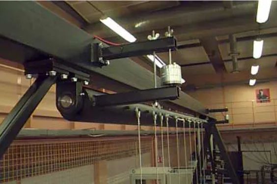
Electromagnetic locking:
A steel pipe connected to the frame via ball bearings is equipped with small steel rods sticking out from the side. The dummy will cause the pipe to rotate due to the leverage developed when the moose is hung from these rods. This is why two electrical magnets fasten the pipe. On given command the current to the magnets is cut and the moose falls down. This rig is calibrated by adjusting the distance from the switch to the rig. This is the method incorporated in this concept.
There is a problem with a transcendental magnetic field, which could delay the releasing procedure. The advantage of adjustable trigging equipment makes this a problem easily dealt with though. A high-speed
Figure 4: Releasing mechanism with electrical magnets.
8.4. Wires
The dummy will be hung from the top spine wire. Each of the vertical wires has a steel ring connected to each end. They all have the exact same length. The rods intended to hang the moose from are only 10 mm long; this is to keep the steel rings from jamming when the dummy falls down.
8.5. Shaping the Rubber Plates
From moose sketches by Bengt Röken and pictures the shape of the dummy was formed. The smooth contour then had to be adjusted, to be well described by 36 rubber plates. A database consisting of 36 plates, and various data on them, was created. The two most important
variables are the height of the plate and the offset of the top wire hole from the plate center. Adjustment of each individual plate finally gave satisfactory results height-wise. The width of the dummy is constant over the body with the exceptions of the plate in the very back and the seven front plates. Moose are surprisingly slim and non-varying in width.
Figure 5: Sketch of rubber plate (cross-section).
Each plate has the shape of an ellipse. It is possible that a drop shaped cross-section could describe the body even better, but this is plain speculation. The dummy is intended to be a simplified model of a real-life moose. Main characteristics have been given priority causing many details to go out of focus. With a model simplified correctly one can hopefully conduct crash tests without getting unpleasant surprises. Another issue of huge importance is that chance must not interfere when testing passenger cars.
With the legs disregarded a moose has its vertical center-of-gravity approximately in the center of the body. The moose’s specifications vary significantly due to the food supply and time-of-year. The body is dense and compact with exception of the belly, which is easy to deform yet heavy. To create a rubber plate that fulfills these specifications hollow sections are distributed over the sheet. The top half has cavities focused to the center while the lower section has cavities in the outer regions. (See figure 5) This causes the lower part of the dummy to be initially soft, while the top part appears more solid. Still the center-of-gravity remains approximately in the center.
This dummy is regarded as competent to demolish a passenger car in an authentic fashion, yet it is easy to use and requires a minimum amount of repair. It can handle large series of crash tests with only short breaks for calibration and cleaning.
Each sheet of rubber has been visualized by using three-dimensional computer software. The plates and other mounting parts was virtually assembled and rendered pictures gave hints of the final result. This procedure showed to be a valuable tool in the designing process. When the result was pleasing a scale 1:5 model was created. Bengt Röken and the crash-safety staff at Saab evaluated the small dummy and some minor changes were performed.
8.6. Manufacturing the Rubber Plates
A drawing was printed for each plate. It only had to show one view due to the simplicity of the design. The paper size had to be A1 in order to fit the largest parts. The pen width used was 0.5 mm. These drawings were delivered to a company in Göteborg. The people at this company are experts at cutting complicated patterns in rubber sheets. They use a very highly pressurized water beam to slice the material. The cutting machine is controlled by an optical reader, which scans the drawings and cuts the rubber simultaneously. The rubber was delivered in the shape of two seven-m2 sheets. The slicing method mentioned above did not warp the edges, which a steel blade would have done. All together 36 large body plates and 80 leg discs were cut out.
8.7. Lateral Wires
The two lateral spine wires (which keeps the rubber plates in position) were initially meant to carefully track a real-life moose’s back column. But later it became obvious that some height between the upper and lower wire was required. This makes the dummy adequately stiff in the vertical direction and also keeps the individual plate non-indifferent to rotating forces. The spine consists of two 10-mm steel wires. Each wire is equipped with a threaded bolt in one end. On the outer end of the thread a wrench seat has been machined. See figure 10. The other end remains non-coated to keep its ability to slip through the wire holes in the plates.
The vertical distance between the steel ropes cannot be to great due to body shape limitations. The plates in the very front and rear are not at level. It is important that the dummy in fact resemble a moose.
Furthermore a tunnel was to be fitted between the spine wires. Finally the distance of 190 mm was decided on (center-to-center). The spine wires also hold the pelvis, shoulders, and end plates in place. When fully inserted the wires are fastened with four competent rope grips. The tightening of the nuts with the torque given in Calibration completes the installation.
Figure 6: Rear plate and looped spine wires.
8.8. Service Tunnel
Between the upper and the lower rope there is a tunnel. This tunnel’s main tasks are to evenly distribute the mass over each rubber sheet and to provide the possibility to assemble the dummy on a rod. The tunnel has the diameter of 110 mm. The layer of rubber surrounding the top wire is thicker than the layer that surrounds the bottom wire. This is due to idea that the top rope should transfer forces in all directions while the lower rope mostly should limit individual plate’s tendencies to rotate.
8.9. The Dummy’s Body
The dummy body consists of 36 rubber plates. They are all 50 mm thick but the area varies. The idea for this construction is based on the fact that the other plates will retain sudden movements of an individual plate. This will create a non-bouncing close-to-solid body.
Soft construction materials tend to deform while under stress. During the impact a rubber body will stretch, which a moose will not. The shape of a moose remains surprisingly intact. Even though the bones break the body will be held together by ligaments, muscles, and strings – and not to forget the hide. It is therefore important that the spine wires can cope with the stress that the impact produces and retain the length expansion. The tensile strength has to be great but the flexibility is very important as well. The large animals are very bendable and non-rigid. This ability is maintained in the dummy with this two-wire concept.
A calculation sheet yielded the total mass, center-of-gravity co-ordinates, and the required area of sheet rubber. A chart based on the calculation data shows a side view projection of the dummy. This would prove to be very helpful.
Figure 7: The side view visualization of the dummy.
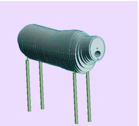
When the parameter set gave satisfactory results they were inserted into a three-dimensional CAD program. Each rubber part was individually sketched and then virtually assembled to give a visualization of the dummy at an early stage of the project.
-1000 -800 -600 -400 -200 0 200 400 600 800 -500 0 500 1000 1500 2000 2500
upper contour lower contour wire1 (upper) wire1 (lower) wire2 (upper) wire2 (lower) center-of-gravity center-of-gravity (horiz.)
Figure 8: Virtually assembled dummy.
Having the above mentioned 3D visualization finalized a scaled down model was created. Bengt Röken and various Saab people evaluated this scale one-to-five model. After this evaluation the drawings were slightly modified – the dummy was redesigned to be a little bit shorter. No fundamental or conceptual changes were performed.
8.10. The Dummy’s Legs
Initially the intention was to simulate the legs with one to three steel wires or chains. A lump of something tough was to be attached to the end – simulating the moose feet. The hooves are tough, wide and, strong. Rubber hoses were to be slipped on the leg wires but this concept would not be life like. The mass on a moose leg is evenly distributed. The above-mentioned construction would be non-appropriate. The mass of a real leg is approximately 8 kg, which is impossible to reach by using only flexible and slim wires. So instead four thin wires lined with rubber discs were incorporated. This concept gives the dummy legs good characteristics.
The legs consist of rubber discs and steel ropes. They start out from the steel plates that simulate the pelvis and shoulders. The force vector is offset from the center-of-gravity causing the body to rotate if the legs are exposed to vertical force. See figure 11. Sketches in the thesis paper from Nilson and Svensson [1] show the position of the moose
throughout an impact. These sketches clearly indicate that the moose’s center-of-gravity barely moves during the initial stage of the accident. The force the moose is exposed to only causes the animal to rotate. The pelvis, shoulders, and belly all rotate with different angular velocity.
9. Results
9.1. Dummy
The horizontal center of gravity is located in the 18:th disc from the rear. This is a good result considering that the head is disregarded in this dummy. The head is very dynamic during an impact. When
determining if the head will cause major destruction chance plays a big role. For example the head is potent to easily break a side window spreading shattered glass in the passenger compartment. But it is very difficult (if not impossible) to predict such damage. Especially when considering that cars vary in width, height, and so on. The long neck will cause the head to start slinging way after the body’s center of gravity first is displaced. A real-life moose has its center-of-gravity around the 7:th rib. This causes the real moose to have slightly more weight on the front legs than the dummy.
Name Pcs Mass Sum
Leg wire 8 0,5 4
Rear plate 1 3 3
Front plate 1 2,9 2,9
Shoulder/pelvis 2 2,75 5,5
Rubber plates 1 307,5 307,5
Spine wire with hose 2 2 4
nuts, wires, rope grip 2 0,5 1
Leg disc 78 0,25 19,5
Leg disc fastener 4 0,1 0,4
Total mass:
348
Table 1: Mass in kilograms.
The sheet rubber revealed a thickness of only 48-mm. This fact adjusted the total mass to 330 kg.
The vertical center of gravity on a moose is placed approximately 1350 mm above ground. The dummy’s center-of-gravity will depend on the leg length, which after consultation of Bengt Röken was decided to extend 1000 mm under the chest. This leg length gives comparable center-of-gravity’s. Once again it is emphasized that every moose is unique. Moose are hard to generalize.
Figure 9: Tightening nuts.
Figure 10: Overview of pelvis, spine wires, and leg system.
The leg origin from the pelvis and shoulder structures. Each leg
consists of four five-millimeter wires. These are mounted according to figure 11 and are interlocked at the bottom end of the dummy’s
shinbone. 19 rubber discs cover each front leg, while the rear legs each have 20 discs.
Figure 11: Dummy hanging from the releasing frame.
9.2. Hanging and Releasing Fundaments
While waiting on being hit the dummy hangs from the releasing frame. Under the top beam there is a pipe connected with ball bearings. The pipe is free to rotate around its own axle. 15 small perpendicular rods are welded to this pipe in a line with 100 mm between them. See figure 4 and 11. When hung on these rods the dummy creates torque around the pipe’s axle due to force offset. A counter momentum is created with two electrical magnets and when their circuit is broken the dummy will fall down. The circuit is broken fractions of a second before impact thus the body is effected by no forces at the time of collision. The dummy is released after approximately 65 ms when the circuit is broken.
Chart 1: Chart of distance related to speed.
During the preparations two M4 screws lock the pipe. These screws should be securely fastened until all preparations have been completed and everything is ready for impact.
10. Verification and Validation
Saab Automobile AB in Trollhättan contributed with two Saab 9-5 passenger cars. These cars were tested in 70 respectively 90 km/h. A high-speed shutting camera filmed the impacts enabling thorough evaluation to be conducted. 0 0,25 0,5 0,75 1 1,25 1,5 1,75 2 2,25 2,5 2,75 20 40 60 80 100 120 140 test speed [km/h] tr igging dist ance ahead of collision [ m ]
The press-on bolts on the spine wires were bent when the dummy tumbled on the ground. Supports for these bolts need to be welded to the front steel plate. When the dummy is hit at greater speed than 70 km/h the rear and front plate are starting to warp. These need to be reinforced, which easily can be done. Furthermore the leg disc retainer needs updating.
Test 1:
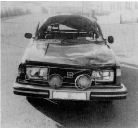
A Volvo 245 were driven into the dummy at 72 km/h. A few leg discs was peeled off each leg due to too small hoof washers. The car
deformations were very pleasing and the dummy behaved well. High-speed cameras produced films that showed a very life-like dummy trajectory. Pictures in Viltolyckor [8] show the same deformations.
Test 2:
A Saab 9-5 was driven into the dummy at 72 km/h. The reinforced leg retainer kept all leg discs threaded on the leg wires. Once again the test car was damaged in a very pleasing way. The result resembled a lot of a real-life accident that had been investigated by Saab engineers.
Test 3:
The second Saab was tested at 92 km/h, which appears to be the upper limit for both passenger cars and dummies. Some damages appeared on the rubber moose after this test. The decrease in speed during the
impact was 15 km/h. The retardation reached a peak value of 10 g.
11. Possibilities of Further Enhancement and Developing of the Dummy
VTI has already been asked to design a camel and horse dummy.
Serious or not this inquiry indicates that there is a worldwide interest in this type of testing. In Australia tests with kangaroo dummies have already been conducted. These are also hard to generalize due to a very dynamic center-of-gravity, which vary very much in vertical position.
This dummy concept is easily transformed to various animals. The CAD model only needs re-shaping. Help from a veterinary or expert on the animal is preferable in order to get the correct characteristics in the dummy. It is important to study the animal thoroughly before making the simplified model that this concept will yield. Compromises could remove characteristic properties (and make the dummy worthless) if not properly conducted.
This concept is very well prepared for simulations using finite element methods. FEM is a very wide spread way to evaluate car
crash-worthiness these days and can be very cost effective compared to real staged accidents. This dummy can be converted into FEM software. It is possible that already existing 3D-models can be imported into some programs.
The head could be incorporated in a dummy concept. This would make the dummy even more appealing. The head and neck would form a pendulum. The pendulum’s resonance frequencies and so on need to be thoroughly evaluated.
12. Appendix
12.1. Components
Horizontal wires:
2 Pcs 2.5-m, 10-mm steel wire with threaded bolt pressed onto one end.
2 Pcs 2-m rubber hose (12-mm inner diameter and 19-mm outer diameter).
4 Pcs Wire grip.
Shoulder complex with front legs:
1 Pcs Shoulder plate (according to drawing). 4 Pcs 2.8-m, 5-mm steel wires.
38 Pcs Rubber discs (according to drawing). 2 Pcs Press-on tube with washer.
Pelvis complex with rear legs:
1 Pcs Pelvis plate (according to drawing). 4 Pcs 2.8-m, 5-mm steel wire.
40 Pcs Rubber discs (according to drawing). 2 Pcs Press-on tube with washer.
Body:
36 Pcs Rubber plates (according to drawings). 1 Pcs Front plate (according to drawing). 1 Pcs Rear plate (according to drawing).
Assembly frame:
1 Pcs Hanging fundament (according to drawing).
Crash test frame:
1 Pcs Hanging fundament with releasing mechanism (according to drawing).
12.2. Assembly
Hanging wires are to be mounted between plate 2-3, 6-7, 10-11, 14-15, 18-19, 22-23, 26-27, 28-29, 30-31 and 34-35.
The pelvis should be mounted between plate 3 and 4. The shoulders should be mounted between 27 and 28.
A non-petroleum lubricant should be used when threading the body plates on the spine wires.
12.3. Calibration
All rubber surfaces are powdered with magnesium carbonate. A rough non-treated surface has a very high friction coefficient, which will make the dummy behave as a solid piece of rubber. A bouncing effect easily comes to mind.
The releasing trigger needs to be set at an adequate distance ahead of impact. (See chart 1.) The upper spine wire should be tightened with the torque of 4 Nm. The lower rope with 2 Nm. The center of the test car should be in line with the boundary between plate 15 and 16. (The plates are numbered from behind)
13. References
1. G. Nilson and M. Svensson, ”Fullskalesimulering av bil-älgkollision medälgkadaver”, Chalmers Tekniska
Högskola, Göteborg, 1986
2. Diverse jägare och naturmänniskor, ”Ett hundra frågor om älgen”, Skogsstyrelsen, Jönköping, 1993
3. B. Almkvist, ”Älgens ålder och kön”, Zoologiska institutionen, Stockholms universitet, Stockholm, 1979 4. M. Lindquist and Ronnie Lundström, “Metoder för att
minska viltolyckor – En översikt”, Vägverket, Region Norr, 1997
5. J. Ifver, “Trafikolyckor på det statliga vägnätet 1992”, Vägverket – Miljö & Trafiksäkerhet, Borlänge, 1993 6. Various, “Bil-Älgkollisioner”, Hedemora Bilteknik, 1984 7. T. Turbell, “Simulerade älgkollisioner – en metodstudie”,
VTI, Linköping, 1984
8. B. Lind, “Viltolyckor”, Volvo (Informationsavdelningen), 1980