Henrik Gustavsson
Institutionen för datavetenskap
Högskolan Skövde, Box 408
S-54128 Skövde, SWEDEN
HS-IDA-MD-97-05degree of M.Sc. by examination and dissertation in the Department of Computer Science.
October, 1997
I certify that all material in this dissertation which is not my own work has been identified and that no material is included for which a degree has previously been conferred on me. Signed: _______________________________________
Key words: CASE, CDIF, Repository, Metamodel, External validation
Abstract
Many contemporary development environments rely on CASE tools to store and manipu-late development information. To be able to integrate different tools a central place of storage called a repository is used. The content of the repository is defined by a meta-model. CDIF is a standard proposal which supports transfer between many different types of CASE tools. CDIF contains an extensive and extensible metamodel which could be used as a transfer format or as a repository metamodel. In this dissertation a set of require-ments for a repository metamodel are then developed and a repository metamodel based on CDIF is defined. The representation of a contemporary CASE tool is mapped into this repository metamodel. The full semantics of the CASE information stored in the reposi-tory is then extracted using an external validation system which transfers the CASE data into natural language. An evaluation of the results against the developed requirements conclude that a repository metamodel which is very close to the CDIF metamodel will not fully meet all of these requirements without changes to the metamodel structure.
1
Introduction...1
2
Background and foundation ...4
2.1 The motivation for CASE tools and repositories ...4
2.2 CASE tools ...5
2.3 Tool integration ...5
2.4 General CASE tool outlook ...8
2.5 Repositories...8
2.6 Requirements on repository meta models...9
2.7 Repository proposals...11
2.8 The CDIF standard...12
2.9 S-designor ...23
2.10 External validation ...31
2.11 ER schemas and natural language...31
3
Problem definition...32
3.1 Objectives...32
3.2 Method ...33
4
Representation of CASE information using CDIF ...35
4.1 The examples ...35
4.2 The mapping rules...37
4.3 Mapping the ER model data ...38
4.4 Mapping the data flow model data...46
5
Extraction of CASE information from CDIF...52
5.1 External validation ...52
5.2 Mapping to natural language ...52
6
Implementation ...67
6.1 Mapping the CDIF metamodel to the IE notation ...67
6.2 Conversion of the CDIF metamodels to relations...70
6.3 The external validation system ...75
7
Critical analysis...77
7.1 Analysis...77
9.3 Additional work with other CASE tools and tool implementation...98
References...99
List of abbreviations ...101
Appendix A (Data model example) ...103
Appendix B (Data flow model example) ...109
1 Introduction
In recent years the trend of systems development has been to use methods containing sev-eral different kinds of models of the system [Nil96]. For the development and mainte-nance of such systems some kind of CASE support is common [Som92,Pre94]. Due to the very large amounts of information being produced by contemporary development envi-ronments such development has to be subdivided so that each developer can work on a subset of the total system. For maximum efficiency and flexibility the developers will require concurrent access to the development information. The situation is hence very similar to database systems [Dat94]. If the CASE information is not universally accessible it will be trapped inside the different tools used by the developers. A repository system will supply a uniform interface with access to metadata and facilities for concurrent access of all information stored in the repository [BUm94]. Experience in the repository area is still limited [BUm94] and it needs further exploration. The overall goal of this project is therefore to explore the potential of repository based systems by elaboration on a standard proposal and to build a prototype of a repository system.
Central to the success of a repository is its metamodel which defines what can be stored in the repository and how to store it. There are several standard proposals in the CASE exchange and repository area [Tan94]. All of these different standards have different goals. Many of the standards originate from the need for seamless integration between dif-ferent tools. The CASE data interchange format (CDIF) standard proposal is primarily a transfer format which will allow metadata to be transferred between different tools which only agree in respect of supporting CDIF transfer. CDIF does, however also supply a com-plete metamodel which according to the CDIF committee could be used as a repository metamodel [CDIF4]. The main aim of this work is hence to assess the suitability of the CDIF metamodel when it comes to direct use as a repository metamodel. To be able to evaluate the metamodel a set of requirements for repository metamodels have been defined.
equivalent representation in the CDIF based repository. CDIF supports several different types of modeling techniques, and a study would benefit from having examined more than one of these significantly different techniques. For this work a data modeling technique and a data flow modeling technique were therefore selected for further study.
The second objective of this project is to extract the information from the repository in a way that preserves the full semantics of the information stored in the repository rather than just extracting the individual constructs. For this project a mapping method and a proto-type implementation for an external validation system was designed which transforms schemes stored in the repository into a natural language representation. Such external val-idation [Bub88] aims to provide a domain expert with a representation of the schemes which can be understood without method knowledge.
Since CDIF not yet has been fully standardized and very few implementations of the stan-dard exists, it is also important to create a physical implementation based on the stanstan-dard. The implementation of the metamodel and the external validation system can also be used to validate the conclusions that have been made regarding the metamodel.
Three main restrictions were placed on this project. The first was to limit the very large set of possible modeling constructs to those available in S-designor hence limiting both map-ping rules and external validation to a subset of the possibilities of CDIF. The second restriction was to use a current relational database for the implementation. This constraint will simplify the implementation since the current generation of commercial relational database management systems have standardized interfaces against programming lan-guages and a standardized database language. The final restriction concerns the use of CDIF. It has been decided that this project will use the metamodel as it is described in the standard proposal without using the extensibility feature of CDIF or changing the meta-model in any other way which will reduce the fidelity to the standard. This constraint was added so that the claims that are made about the standard are grounded directly in the stan-dard and not in the extension of the stanstan-dard. An overview of this work is provided in fig-ure 1.
Figure 1: Outline of problem area
}
}
}
Mapping(only from S-designor)
Information extraction (External validation)
Repository metamodel
The main focus of this work
Used to populate the repository with data
Used to evaluate the Schema in S-designor Customer ID Adress Payment Invoice ID Name Tabasco Cucumber ID Speed Customer ID Adress Payment Invoice ID Name Tabasco Cucumber ID Speed
and to evaluate the
metamodel representation
2 Background and foundation
2.1 The motivation for CASE tools and repositories
Many modern applications are based on a distributed Client/Server architecture with large databases using application clients containing the necessary logic [Dat95]. Development of this kind of applications require that the developers maintain large amounts of develop-ment information. Modern information systems developdevelop-ment methodologies [Nil96] require that the developers use several different description techniques to model an appli-cation. The development of a single information system may for example, involve the par-ticipation of 20 or more developers, some of whom use different kinds of workstations to model different parts of the application using different kinds of development tools. To be able to achieve maximum efficiency and flexibility the development information will need to be shared.
Figure 2: Modern large scale application development
DFD ER DFD ER DFD DFD
MODELS
SHARED
2.2 CASE tools
The usage of case tools is to many developers a quite new experience. Or in the words of Pressman [Pre94]:
“Everyone has heard the saying about the shoemaker’s children: The shoe-maker is so busy making shoes for others that his children don’t have shoes of their own. Over the past 20 years, many software engineers have been the “shoemaker’s children”. Although these technical professionals have built complex systems that automate the work of others, they have used very little automation themselves”
“Today, software engineers have finally been given their first new pair of shoes - computer-aided software engineering (CASE)“
Many of the “shoemaker’s children“ are trying on their first pair of new shoes and they do not yet fit them properly [Pre94].
The overall aim of CASE technology [LoK95] is to improve the productivity and quality of a resulting application by helping the developer throughout the development process. Support should be given to all the different steps of application development both the requirements specification stages as well as the more implementation oriented stages. The tools are needed since manual storage and manipulation of this important information will undoubtedly introduce numerous errors which will be reduced if the process is partly or fully automated.
2.3 Tool integration
For smaller applications CASE tools that focus on a very limited part of the software engi-neering activities can be used to good advantage. However, to be able to produce large application systems it is of paramount importance that different tools and diagramming techniques can be integrated [Pre94]. Gene Forte [For89] makes this point very clear:
lies in the potential to integrate many tools into an integrated environment.”
Data exchange: The simplest form of integration between completely separate CASE
tools is through data export and import using some kind of common data format so that other tools can import data from the tool (figure 3a). The problem with this kind of archi-tecture is that the data is usually difficult to extract and mismatches between the represen-tation in the target tool and the source tool will result in information loss [Pre94].
Common tool access: The next level of integration [Pre94] (figure 3b) is when the tools
can be loosely integrated using a common user interface. The coordination between differ-ent tools is achieved manually through some kind of user action. Similarly to when com-pletely separate tools are used, some information will be lost in the translation.
Common data management: To be able to benefit fully from the integration it is
neces-sary to share the CASE tool data centrally without the need for translation between differ-ent tools [Pre94] (figure 3c). Data from differdiffer-ent tools can be maintained in a cdiffer-entral or distributed logical database. The information exchange is simplified and integrity of CASE tool data is maintained. The work of different developers can typically be merged into a total model of the system. Although the data from different tools is managed together no tools have explicit knowledge of the metadata stored inside different tools. As a consequence it is still necessary to use some kind of export mechanism to share data between the different tools.
Full integration: To achieve full integration (figure 3d) it is required that the system
sup-ports both metadata management and a control facility. Metadata is information about the software engineering data produced by the individual CASE tools [Pre94]. The metadata consists of the following different parts:
• Object definitions (e.g. datatypes attributes)
• Relationships and dependencies among objects of arbitrary granularity (e.g. a pro-cess on a DFD diagram and an entity)
• Software design rules (e.g. how to draw a data definition diagram)
The control facility allows tools to notify other tools about changes in the development environment or the system being modeled. This can be, for example, when a design tool triggers some kind of response in the configuration manager.
Tool A Private Data Translator Tool B Private Data Common User Interface
Tool A Private Data Tool C Private Data Common User Interface
Tool B
Private Data
Tool A Tool C
Common User Interface
Tool B Shared Data Shared Data User Action B) D) C) Tool A Private Data Translator Private Data Tool B A)
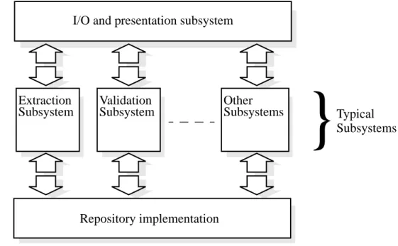
Regardless of whether CASE tools are integrated with other tools or not, most of them have certain subsystems in common as can be seen in figure 3 [Bub88]. The I/O and pre-sentation subsystems contain the user interface and file manipulation systems which allow the users of the tool to manipulate the data stored in the tool. In addition to this basic func-tionality the tool has a number of subsystems which will help the developers to model the application. Figure 4 highlights some examples of some typical subsystems. The extrac-tion subsystem will extract informaextrac-tion from the repositories of other tools and translate it to a format that can be understood by the repository. The validation subsystem will help the developer to make the specification meet the needs of the users [Bub88].
Figure 4: General CASE tool outlook
2.5 Repositories
Repositories and CASE tools have received much attention lately, but there is however no clear and consistent definition of what a repository actually is. A good starting point for an explanation of the repository concept is the definition found in Websters dictionary [Web74]:
“Any thing or person thought of as a center or accumulation of storage” Other
Subsystems I/O and presentation subsystem
Extraction
Subsystem ValidationSubsystem OtherSubsystems
Repository implementation
}
Typical SubsystemsAs pointed out by Pressman [Pre94] in the early history of software development the repository was indeed a person and not a piece of hardware. The person was later replaced by a database. A repository is hence a shared database of information about the engineered artifacts produced or used by an enterprise[BUm94]. However, database functionality alone is not sufficient for a repository. A repository also performs the following functions [For89]
• Data integrity support is necessary to ensure consistency, for example when an object is removed the updates have to be cascaded.
• Information sharing is required so that multiple users can be able to use the tool simultaneously.
• Support for tool integration is an obvious functionality that is required for the repos-itory since tool integration is the main use for the reposrepos-itory. The database must therefore be open to other tools.
• The repository must also enforce the development method used to develop the schemes.
• The repository will also help the developers to standardize the documents since they are stored in a consistent manner.
The importance of the repository is stressed by Pericles Loucopolous [LoK95] when he states that repositories are central to any CASE architecture and if used properly a reposi-tory would then be used to store all development information throughout a development lifecycle.
2.6 Requirements on repository meta models
One of the main differences between a repository and a traditional database system is the use of a meta model. A meta model is a schema for a CASE database, and defines what information can be stored in the repository and how to store it [Wel89]. A metamodel also
A repository metamodel should be able to capture all CASE information from an informa-tion system under development. The representainforma-tion of the informainforma-tion has to be indepen-dent of the mode of entry and analysis of the data. The representation of the CASE data must hence be “lossless“ in the sense that no information in any notation used for develop-ment should be lost when it is stored in the repository [Wel89].
In the ideal repository metamodel it should therefore be possible to regenerate the com-plete representation of the information stored in the repository given a CASE tool with a perfect transformation ability.
2.6.2 Non redundant representation
Very similar to the representation in an ordinary database system the metamodel should also be non redundant [Wel89]. If a metamodel has redundancy then changes in a model-ing object or a relationship between different objects will require changes in more than one place. Using a non redundant metamodel would eliminate any inconsistencies and update anomalies introduced by such redundancy.
The ideal repository metamodel should have no redundancy in the representation. If this is not possible, a metamodel should strive towards a representation that is as free from redundancy as possible.
2.6.3 Simplicity
If a repository is to be used in an organization it must provide a representation that is natu-ral to the users of the repository. The structure of its metamodel must therefore map as closely as possible to the representations used to model the information system [Wel89]. From this requirement it can also be inferred that the structures should be sufficiently sim-ilar across the different representations so that the use of the repository metamodel is nat-ural when the different parts of the repository metamodel are used together.
2.6.4 Correct level of granularity
An effective metamodel has to have a correct level of granularity. If several concepts are aggregated together then detail is reduced and querying will be simplified, but information
will therefore need to be extracted from the compound object. If the level of granularity is too low the extraction of the semantics stored in the repository will be very expensive since the information has to be extracted using complicated queries and join operations [Wel89].
Difficulties similar to the redundancy difficulties are also introduced when the granularity level is too low and an update is performed. The set of related objects that will also be required to be updated has to be calculated using complex queries [Wel89].
2.6.5 Extensibility
The metamodel has to be extensible so that unsupported semantics can be added. This type of evolution will be needed if the methodology changes or new tools are added to the development environment or if a new notation is needed for a particular purpose [Wel89].
2.6.6 Performance
Performance issues are very important for repositories and repository metamodels [BUm94]. Due to the inherent complexity in CASE information a single transaction may be very long. One solution to that problem is the use of check in and check out. A Check out is when a modeling object is locked and moved to one of the users’ private workspaces for further manipulation. A check in is when a modeling object is removed from the work-space of the user and is reinserted into the repository [BUm94]. If the representation is non redundant and the granularity is sufficiently low a check in or check out can be performed using a short transaction. But the more complex the representations or the queries get the longer these operations will take. Measures of the performance will reflect all of these conditions and is hence a combination of several of the other requirements.
2.7 Repository proposals
If it should be possible to use the repository from the outside it is necessary that meta data definitions are agreed between different tools. The only viable way to achieve this is to use
• IRDS (Information Resource Dictionary System)
• PCTE (Portable Common Tool Environment)
• ATIS (A Tools Integration Standard)
These different standard proposals cover a wide selection of different approaches to repos-itories, tool integration and exchange. Some of these are aimed at specific development techniques or models while others are more general.
For this project the CDIF standard proposal was selected for this project for two main rea-sons. CDIF is a standard proposal which was originally intended as a transfer format, but it has also evolved into an extensive metamodel specification which could be used as a repository metamodel. Secondly, CDIF also strives to support as many different types of CASE information as possible by both offering a large set of subject areas and the possi-bility to extend the metamodel.
2.8 The CDIF standard
CDIF can be used for a wide range of different purposes. It can be used to represent a wide range of different models and the possibility of extending the representations so that it can be used to represent an even wider range of different models.
The CDIF standard proposal is not a single standard, but a family of standards covering several different areas. The primary purpose of CDIF is as a description of a mechanism for transferring information between CASE tools. The transfer format specifies the con-tent and the format of the transfer file (or by any other media capable of information trans-fer). The standard facilitates a successful transfer when both the exporting and the importing tools agree on conformance to CDIF.
As can be seen in figure 6 the CDIF family of standards include an integrated metamodel and a transfer format definition. The standard also includes a meta-meta model and a set of associated rules that define a framework for the integrated metamodel and the transfer model.
Figure 5: The CDIF family of standards (Adapted from [CDIF2])
The CDIF workgroups are open to any CDIF member who has an interest in the group. Each group has a chair which is officially determined by consensus. The CDIF standard documents pass several different votes among the members before it is published as a standard. The CDIF members come from several companies in different areas and from various universities around the world.
2.8.1 CDIF and extensibility
There are numerous different kinds of schemes or other kinds of documents that are candi-dates for this kind of transfer between tools [CDIF1]. These different kinds of documents can be identified by their place in the software development lifecycle (SDLC). There are several different models of the SDLC; CDIF does not require any specific kind of SDLC. In figure 6 there is an example of a model for a hypothetical SDLC. The ultimate goal of CDIF is to support transfer of information for any kind of information that lies within this hypothetical SDLC [CDIF1].
This goal is unlikely to be met for some time yet since many tools have aspects that are unique to those specific tools, and other tools cover parts of the SDLC that are not covered
CASE data interchange format Integrated Meta model Transfer Format Foundation Common Subject Area General rules for transfer Syntax Encoding
[CDIF1].
Figure 6: A general development life cycle (Adapted from [CDIF1])
2.8.2 The separation of semantic information and presentation
The CDIF standard is divided into several different subject areas. The different subject areas can be said to be different views of the underlying metamodel. The different subject areas can be grouped into two different categories, the semantic information subject areas and the presentation information subject areas [CDIF1].
The semantic information subject areas define the underlying schema for the CASE tool repository. This information guides how the information entered by the users shall be stored. These areas do not cover how the information is to be presented to the user of the tools. The subject areas in the presentation category define how the tools shall present the information in the tool to the user. Presentation information covers concepts like dia-grams, tables and matrices.
Planning Requirements Engineering Logical Design Physical Design Implementation Testing Maintenence De v elopment Lifec ycle
2.8.3 The separation of the ‘what’ from the ‘how’
One of the main underlying ideas behind CDIF is the separation of what information is to be transferred from the definition of how to transfer it. The information content of the meta model defines content of the CDIF transfer. The transfer format defines how the information must be organized for a successful transfer [CDIF1].
The metamodel and the transfer format both share the metametamodel which defines the rules and building blocks from which both the metamodel and the transfer format are specified. This relationship is illustrated in figure 7.
Figure 7: CDIF architecture (Adapted from [CDIF1])
2.8.4 The layered approach used in CDIF
As depicted in figure 8 CDIF uses a layered approach where several layers of models together define the contents of a transfer [CDIF1]. Each level at a higher abstraction level defines the models on the lower level. Each abstraction level defines the rules for the level from which it is abstracted.
• Metametamodel (The metametamodel defines the structures used to design the metamodel.)
• Metamodel (The metamodel defines the structures used to store the models) CDIF Meta-meta model CDIF Meta model CDIF Transfer Format
metadata structures for storing diagram types, notations and syntax. As a whole this set of definitions is called the metametamodel because it contains the data about the data about the data.
Metamodel: The second layer from the top defines the structures (standardized or
other-wise) used to store the models are meta models, so called since they are in fact models about models. In CDIF the abstract definitions of such data structures are defined using a variation of Entity-Relation modeling. This representation contains the type definitions for the different data items used to store models (e.g. the definition of an entity).
Model: The second lowest layer is the model layer. A transfer between the different tools
consists of such models. A model is a description of user data. (e.g. the definition of a cus-tomer entity)
User Data: The lowest level in the figure the user data is not defined in the CDIF
stan-dard. The standard does only help the users of the tools used to produce the schemes for this data.
Figure 8: The CDIF layers (Adapted from [CDIF1]) META MODEL
META ENTITY ATTRIBUTEMETA
ENTITY
ATTRIBUTE RELATIONSHIP
CUSTOMER
SALES CALL CUSTOMERLOCATION
ID CUSTOMER NAME 121 245 316 734 Todd Kirkhammet James Hetfield Lars Ulrich Jason Newstedt META-META MODEL USER DATA Defines (Tool independent) META MODEL Defines (Tool dependent) MODEL Defines (Instance stored in tool)
The ultimate goal of the metamodel is to provide definitions for all the information needed in CASE tools. This task cannot be completed in only one step [CDIF1]. The solution to this problem used in CDIF is to divide the standard into a number of smaller parts called subject areas. Each subject area can be used without any prior knowledge about any of the other subject areas. Each subject area is defined in a separate standard document.
In each subject area the meta entities, meta attributes and meta relationships included sup-port the information needed for most models covered by the subject area. If the informa-tion in some particular tool does not fit the informainforma-tion specified in the subject area it can be provided using the extensibility mechanism in CDIF
The main subject areas of some interest to this work are:
• Foundation subject area (Contains the basic information about the metamodels)
• Common subject area (Contains the definitions that are shared between all meta-models)
• Data definition subject area (Contains definition of the data elements and data struc-tures used in CDIF)
• Data modeling subject area (Contains the definition of a metamodel which Provides support for ER models)
• Physical Relational database subject area (Contains the definition of a metamodel which Provides support for the physical relational model)
• Data flow modeling subject area (Contains the definition of a metamodel which Pro-vides support for data flow models)
• State/event subject area (Contains the definition of a metamodel which Provides support for states and events and finite state modeling)
• Presentation Location and connectivity subject area (Contains the definition of structures used to graphically represent different concepts)
Foundation subject area: The foundation subject area is used as a basis for the definition
of all the other subject areas. The meta objects defined in the foundation subject area are used in the definitions of the other subject areas. All meta entities, relationships and attributes in the other subject areas must inherit the properties defined in the foundation subject area. This subject area must be used in any valid transfer regardless of whether any other subject areas are used or not. If no other subject areas are used the metamodel used for the transfer is described using only the extensibility feature of CDIF [CDIF1].
Common subject area: The common subject area contains information which is common
to all systems engineering objects. This information includes details like the creator of a particular object and the synonyms for objects. This subject area also contains the defini-tions of different supertypes used to classify the meta objects used in the other subject areas. The common subject area will be used if any other subject areas other than the foun-dation is used in the transfer since it will define the common structures for all those sub-ject areas [CDIF1].
The data definition subject area: The data definition subject area contains the
informa-tion needed to define data elements and data structures. These structures are referenced by the other subject areas when defining the data content of any metaobject. The data defini-tion subject area supports simple and complex structures as well as inheritance, there is also support for defining types and domains [CDIF1].
The data modeling subject area: The data modeling subject area provides support for all
the major forms of ER models as well as logical modeling to support the logical design of relational databases. The subject area contains support for among other things the follow-ing [CDIF1]:
• The subject area has support for roles on relationships and a multitude of different types of relationships can be expressed (e.g. one to one, one to many and complex n-ary relationships all with the possibility of specifying cardinalities).
data definition subject area [CDIF1].
The data flow modeling subject area: The data flow modeling subject area provides
support for modeling the input-output-processs view of the system. It provides all the con-cepts needed for data flows into and out of processes with associated data stores and exter-nal entities.
The concept of process, flows, stores and entity decomposition is supported. The data con-tent of the data flow area is described by reference to the data definition subject area [CDIF1].
Physical relational database subject area: This subject area models the physical
imple-mentation of relational database designs [CDIF1].
State / Event subject area: The state event subject area contains semantic information
regarding event-driven finite state machine modeling. State-event modeling covers com-ponent states, actions transitions between states and their enabling events and conditions.
Presentation Location and Connectivity subject area: The presentation location and
connectivity subject area defines how to represent the spatial location of specific instances or the relative position of different instances. This information is only used for the graphi-cal representation of semantic objects.
2.8.6 CDIF Instantiation diagrams
When a model is instantiated in CDIF, additional objects are introduced that are new to the modeling techniques used for the model. To be able to represent the instantiated models diagrammatically additional modeling objects are introduced.
The instantiation diagram for the data model: Some minor changes have been made to
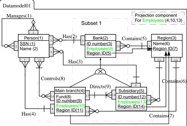
the basic ER notation (from S-designor) used for this project. These additions are mainly due to the fact that CDIF uses a more low level representation and a representation for the foreign key is therefore required, and that CDIF uses a more complicated representation for the relationships which would allow the metamodel to represent more complicated relationships. The folder and the box that represents the projection component are added for visual purposes.
Figure 9: The folder
The folder is used to represent the containing data model which contains all the other data-modeling objects.
Figure 10: The projection component
The projection component symbol is used to represent the projection components that indicate which other datamodeling objects that are used in the projection.
Figure 11: The foreign key
The foreign key symbol is used to represent the foreign keys in the model. The arrow points in the direction toward the primary key that the foreign key references.
Figure 12: The Role/Role constraint
The small shaded rectangle represents one instance of a role and one instance of a role constraint, connected to each other. The two objects grouped together will name the roles of the relationship and provide the cardinalities as well as give the identifier of the entity to which that particular end of the relationship is connected.
Instantiation of a data flow model: Some minor additions have been made to the data
flow modeling technique described in OMT [RBP92]. All of these additions have been made because CDIF uses several different objects to connect the different modeling objects to the flows except for the subdivision and the folder symbols that were added for
Projection component ForEmployees (4,10,13)
Figure 13: The folder
The folder is used to represent the containing data flow model which contains all the other data flow modeling objects.
Figure 14: The subdivision symbol
The subdivision symbol is used to indicated that a set of modeling objects are contained in a process.
Figure 15: The equivalence set symbol
The equivalence set symbol is used to indicate that two or more modeling objects are exactly identical and i.e. are instances of the same object. The equivalence sets are used in the example as described above to mainly connect various modeling objects.
Figure 16: The referenced element symbol
The referenced element symbol is used when several data modeling objects are connected to indicate the order in which they are connected.
Figure 17: The flow ports
EQ1
The port symbol is used to connect the flows to other modeling objects. The port symbol is a black or shaded rectangle. The name of the port is written beside the port and the name also indicates the type of the port. A port that is named Ip1 is an input port and a port named Op1 is an output port.
2.9 S-designor
Several of the contemporary CASE tools have open repositories and support for different modeling techniques. One representative of this new breed of CASE tools is S-designor [Sde95] from Powersoft. The repository that S-designor uses is stored in a relational data-base (RDBMS), which is accessed using ODBC [ASo95] which in turn means that any ODBC capable RDBMS can be used to store the repository data.
Two conceptually different modeling techniques in S-designor were selected for further study, the EER technique used to create the conceptual data models (CDM) and the data flow technique used to create process activation models (PAM).
2.9.1 The S-Designor EER model
There are several different entity relational modeling techniques most of these are based on the original ER model proposed by Chen [Chen76]. S-designor uses an extended ER model based on the Information Engineering notation [MaM85]. The conceptual modeling technique (CDM) also has a corresponding physical model (PDM) which will not be cov-ered in this work.
Figure 18: An entity
Entity: In S-designor the entity is represented as a rectangle with the name of the entity at
the top of the rectangle, a line is used to separate it from the attributes which are listed below the name. Underlined attributes are part of the primary key.
Entity name Key
Attribute 1 Attribute 2
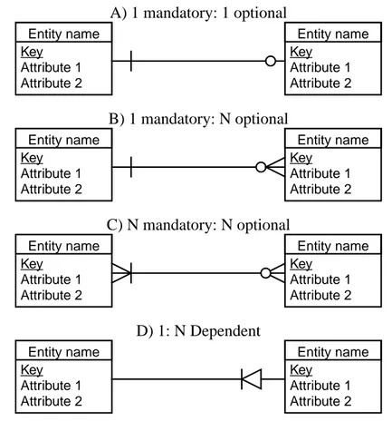
ing a circle making it optional. Weak entities as described by Elmasri [ENa94] can be expressed using a dependent relationship as can be seen in figure 19D.
Figure 19: Relationships
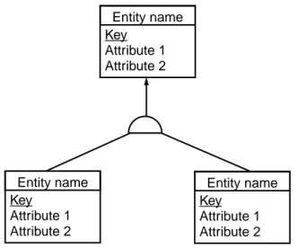
Inheritance: One of the main advantages that the EER models have over the original ER
model [ENa94] is the possibility to express inheritance. In S-designor inheritance is expressed using an arch connecting the different entities, with an arrow pointing in the direction of the supertype. Disjoint membership can be expressed using a cross in the arc.
Entity name Key Attribute 1 Attribute 2 Entity name Key Attribute 1 Attribute 2 Entity name Key Attribute 1 Attribute 2 Entity name Key Attribute 1 Attribute 2 Entity name Key Attribute 1 Attribute 2 Entity name Key Attribute 1 Attribute 2 Entity name Key Attribute 1 Attribute 2 Entity name Key Attribute 1 Attribute 2 A) 1 mandatory: 1 optional B) 1 mandatory: N optional D) 1: N Dependent C) N mandatory: N optional
Figure 20: Inheritance
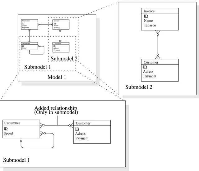
Submodels: In S-designor it is possible to specify submodels. As depicted in figure 14
any data model object can participate in one or more submodels. Membership is not dis-joint and a single object can hence participate in several different submodels. A model can contain several different submodels each containing other submodels. As exemplified in figure 14 in S-designor a data modeling object can be part of a submodel and not be a part of the model that the submodel is part of.
Entity name Key Attribute 1 Attribute 2 Entity name Key Attribute 1 Attribute 2 Entity name Key Attribute 1 Attribute 2
Figure 21: S-designor submodel structure
2.9.2 The S-Designor Data flow diagram
The data flow model used in S-designor is based on the functional model used in OMT [RBP92]. A data flow diagram (DFD) is a graph which shows the flows between different processes in a system.
Process: The process, denoted by an ellipse is a transformation of some value of some
kind. The functional model only shows all possible functional paths it will not show which of the flows that will actually occur.
Data store: The data store is a passive object which stores data for later access. A data
store is drawn using two parallel lines containing the name of the store. A data store does not actively participate in a process, it only reacts to requests to store and retrieve data.
Model 1 Customer ID Adress Payment Invoice ID Name Tabasco Cucumber ID Speed Customer ID Adress Payment Submodel 1 Submodel 2 Cucumber ID Speed Customer ID Adress Payment Submodel 1 Added relationship (Only in submodel) Invoice ID Name Tabasco Customer ID Adress Payment Submodel 2
Input arrows indicate that the information in the store is changed. Output arrows show that the information is being retrieved.
Actor object: Unlike the data store the actor object is an active participant in the data
flow. The actor produces and consumes values. Actors are attached to the inputs and out-puts of a data flow graph. Actor objects can be sources of flows as well as endpoints (ter-minators) of the flow.
Figure 22: The key concepts
Data flows: The data flows connect different processes, stores or actor objects. The flows
are represented using arrows. Each flow represents a value at some point in the computa-tion.
Figure 23: Flows
Flows can be duplicated, creating exact replicas of the data values in the flow. Flows can also be decomposed into several component flows. It is also possible to merge flows into composite flows containing the values of all the constituent flows.
process name Process Name of data store Data store Name of actor object Actor object
process data name
Data flow data name Control flow Data store Flow which results in store process process process
Figure 24: Operations on data values
The values in the data stores can be updated or read. This can be achieved by making flows from or to the stores from processes. A single flow can both update and read a data value from a store at the same time.
Figure 25: Operations on data store values
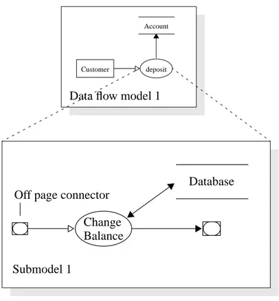
Data flow models and submodels: As depicted in figure 19 any process can in
S-desi-gnor have a submodel connected to it. This submodel can contain any data flow model object. All processes contained in the submodel are hence subprocesses of the original process. All flows that enter or leave the process are represented using off page connec-tors, this means that the flows can be directed to subobjects of the original process.
composite d1 d2 composite d1 d2 Decomposition Composition d1 Duplication d1 d1 d1 process process process Data store Data store Data store Acess Update
Figure 26: Data flow model submodels
2.9.3 The S-designor metamodel
The conceptual model of the S-designor internal metamodel is not taken from any docu-mentation supplied with the system, it was developed using reverse-engineering of the database used to store the schemes together with the partial information supplied in the mauals. Since reverse engineering was used the schemes are perhaps not fully consistent with the intentions of the developers at Powersoft but the overall structure should be roughly the same. Some of the cardinalities of the relationships do not fully agree with the database, but they were added to increase the clarity of the model.
Submodel 1
deposit Account
Customer
Data flow model 1
Off page connector Change Balance
Figure 27: The S-designor metamodel
Due to the very compact look of the metamodel it seems that the intention of the designers of the metamodel has been to make the metamodel model minimal. This means that as lit-tle data as possible has been stored about the various objects and that the number of rela-tions in the database has been kept to a minimum. Both the data models and the data flow models have been stored in an identical framework so that both the data model and the data flow model parts of the repository metamodel are accessed in exactly the same way. The set of relationships between the different modeling objects has also been reduced to a very small set of essential relationships.
Submodel
Project Model
Object
Entity Attribute Relationship Inheritance Inh. Link Offp. C Process Store Ext. Agent Flow
Node Object
2.10 External validation
When an application is being developed the developers do not always have relevant knowledge about the domain that the system is being developed for. In many cases some expert on that particular domain is consulted during the development process. The devel-opment information supplied by the developer may however not be easily understood by the expert since many domain experts do not posses the required method knowledge about the method the developers use [LoK95]. The development information must then be pro-cessed in a method independent way that can be easily understood by the domain expert, e.g. a natural language representation of the schemes.
Figure 28: Domain knowledge vs. Method Knowledge
2.11 ER schemas and natural language
Several different methodologies which will map a description in natural language to an ER schema have been suggested over the years. The method suggested by Chen [Che83] is not intended for automation of the mapping process while other methods are suitable for automation [WiP95]. Additions to such methodologies can be performed so that the com-mon enhanced ER (EER) [ENa94] modeling techniques can be supported. No similar type of methodology has however been suggested which will map a description in natural lan-guage to a data flow diagram.
Domain Expert Application Developer Domain Knowledge Method Knowledge Has little Has much
3 Problem definition
3.1 Objectives
The overall aim of this project is to assist the future implementation and use of reposito-ries in development environments. Central to the repository concept is the metamodel which contains the definitions of all the data structures that can be stored in a repository. A standard proposal in the CASE area that contains an extensive metamodel with support for several different types of schemes is CDIF. The main use for the CDIF standard pro-posal is as a transfer format between different tools. An objective of the CDIF standard proposal however states that the goal of CDIF is [CDIF4]:
“To provide a precise, unambiguous definition of information representation. This applies to both static file transfer and repository content definition.”
This objective specifies that CDIF should not be limited to use as a transfer file format but should be considered for use as a repository metamodel. The primary aim of this work is hence to evaluate the metamodel as a repository metamodel and to investigate whether CDIF is a suitable candidate for a universal repository metamodel.
To be able to perform the evaluation a set of requirements for a repository metamodel have been defined. The objective is then subdivided into two subobjectives. The first sub-objective is to evaluate the representation of CASE data, the second is to extract the full semantics of the information stored in the repository. Results from these two subobjec-tives will then be evaluated against the requirements.
As already stated, a set of constraints have been put on this project to simplify its execu-tion. The results of the study will be affected by these constraints, which will limit the applicability of some of the results.
• The representation of the CDIF metamodel will only be compared with a single CASE tool. Any flaws in the representation will therefore only be compared to the representation of this tool. The tool selected for this project is S-designor which has been discussed in a previous section. From the diagramming techniques available in S-designor the data flow modeling and the entity relationship modeling techniques were selected for further study.
• Fidelity to the CDIF metamodel is kept as high as possible. This means that the model is not changed or extended in any way and no additions have been made using the extensibility feature of CDIF.
• The metamodel is implemented using SQL-92 in a current generation relational DBMS.
3.2 Method
The method used to meet these objectives is divided into three parts. The representation in the CDIF metamodel is evaluated by systematically mapping each of the modeling con-structs available in the selected tool into the repository. Since the modeling concon-structs are mapped individually there are however no guarantees that the mapping rules will be able to handle any combinations of the different modeling constructs.
The information extraction part of the evaluation is performed by extracting each of the constructs by creating an external validation document containing the full semantics of the stored CASE information. The external validation is constructed using string concatena-tion and problems with extracting combinaconcatena-tions of the different constructs are therefore avoided since each module is fully disjoint. The result of both the mapping and the extrac-tion will then be compared to the requirements for the repository metamodel.
The final part of the method consists of a validation of the theoretical findings by a com-plete implementation of the metamodel and the external validation system so that the results can be grounded in a physical implementation.
Figure 29: Method outlook Insert statements contained in appendix A and B Example schema contained in appendix A and B S-designor representation described in section 2.9 CDIF metamodel implementation described in section 6 External validation example contained in appendix A and B Representa-tion described in section 4 Extraction described in section 5
4 Representation of CASE information using CDIF
4.1 The examples
To clarify the formulation of the mapping rules an example is required. The example will contain all the necessary structures of the tools as well as being so close to commonly known real world structures that it can be understood by a large range of people not com-pletely familiar with the particular area at study. The example schemes that were devised are somewhat based on similar examples in [ENA94,RBP92] but they were adopted to fit the semantic possibilities of S-designor.
4.1.1 The ER model example
This simple example is set in the area of banking. The model captures a very limited sub-set of the information needs of a chain of banks. The executives of the bank will need information about the bank offices and how they are distributed over a set of geographical regions. They will also need various administrative information about the banking person-nel and how they are connected to each other and to the different offices.
• A person is identified by his SSN. The name of each person is also stored. A person can have several subordinates and a person can also be managed by several manag-ers. A person can also control several main branches.
• A bank is identified by the ID number together with the region number it is con-tained in. A bank also has a projected attribute called employees which is a projec-tion of the number of employees that the particular bank has. A bank can have several persons as employees.
• A region is identified using the region number. Each region is also assigned a name.
• There are two types of banks. The two types of banks are called main branch and subsidiary.
A subsidiary must be directed by a main branch.
• Finally there is a subset of the model containing the bank entities and relationships i.e. the bank entity and the two subtypes and any relationships between them.
Figure 30: The ER example model
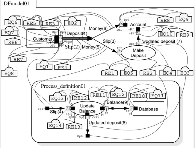
4.1.2 The data flow model example
The second part of the example is taken from the information system of this fictitious bank. The system developers of the information system will need to make a data flow model of the part of the information system that manages the deposits that clients make.
• A customer makes a deposit. The deposit contains both the physical money and the slip containing the sum and the account number.
• There is a process that will make all the necessary updates based on the information in the slip. Finally the updated balance is sent to the account.
• Inside the process that takes care of the deposit there is a subprocess that will read and write the balance from the database containing among other things the account number and the balance. The balance is then sent through to the outside of the pro-cess. Person SSN Name Manages Subordinate Manager Bank ID number Employees Region Name Region ID Employee Employer Has Contains Main branch Fund Subsidiary Directs Local office Head office Object Area Controls Manager Office Subset 1
Figure 31: The data flow example model
4.2 The mapping rules
Mapping a schema into CDIF using a program is a fairly complex task. Programmatically this task is completed in several different steps, and the information is stored in the repos-itory when these steps are finished. Only rules for transferring the model into the reposi-tory are supplied. Methods for the lower level of the transformation are not fully provided, this document will contain only the general rules for transforming a model from the inter-nal structure used in S-designor into the CDIF based repository.
As can be seen in figure 32 there are several different models involved which all support a different set of modeling constructs. The most interesting part is the area where all these different models intersect.
Customer Make Account Deposit Deposit Money Slip Database Updated balance Update Balance Slip Balance Updated balance
Figure 32: Semantic content of the different models
The semantics provided by CDIF are however so much richer than the semantics of S-designor that a tool working with the repository could not work to its full potential unless it was possible to extract the richer semantics. The mapping rules will therefore first an foremost map the basic representation of S-designor. In order to get closer to CDIF some of the rules will however be able to add semantics through user interaction within the mapping process. Even when these semantics are added through user interaction there is a large semantic gap between the different representations.
4.3 Mapping the ER model data
The metamodel in S-designor is significantly different from the metamodel used in this project. This is partly due to the fact that the designers of the S-designor metamodel have selected other methods to implement inheritance.
The main entity in the CDIF metamodel is the “attribute” entity, which is connected to many other entities. The main entity in the S-designor metamodel is the “entity” entity which is connected to my many other entities. This difference will make the stored data in the CDIF based repository metamodel look very different from the data as it is stored in S-desingor even though they contain the same semantic information.
Due to the reasons outlined above the semantic gap between the two models is quite large and a mapping process will need to bridge this gap.
S-designor CDIF
4.3.1 Mapping the model and project information
The information stored in S-designor about the models is very limited and amounts to not much more than the name of the model and the time of creation and of the latest update. This information is mapped to equivalent names and unique identifiers in S-designor. In S-designor a model is stored in a higher level container called a project. The project information has no corresponding information in the data modeling CDIF metamodel. In the latest version of the standard there is however an entire subject area devoted to project management that can be used to represent the very limited information about the projects stored in the project entity. The project management subject area is not examined further in this particular project and the mapping of the project entity is hence left out of this work and it will not be mapped to any similar concept in CDIF.
In the example supplied with the document the project information is completely removed. For each of the model instances in the example a model instance is created in the repository, the only attribute of the model that is transferred in the example is the model name. In the supplied example the model has the identifier Model01 and the type of the model was set to fourth normal form (4NF).
4.3.2 Mapping the entities
Since the entity is the main object in S-designor it is natural to continue the mapping pro-cedure with the entity objects. The only information stored in the shared identifier table that is converted is the name of the entity and the model that it is stored in together with the unique identifier. S-designor has several different types of unique identifiers, a model-ing object is uniquely identified by both an integer that is used as the key, connectmodel-ing the different tables and several different types of unique names that are used as semantic iden-tifiers understood by the user of the tool. No information from the entity specific informa-tion is converted since it is not needed to fit the CDIF representainforma-tion.
ization state was also set to 4NF.
4.3.3 Mapping the attributes and the identifiers
In S-designor there are several different types of attributes. An attribute can be an ordinary attribute or a primary key with or without optional data content. All this information is stored in several different tables since S-designor stores the data items separately from the actual attributes. In CDIF the attributes are stored as separate object while the keys are indicated by a separate candidate key object which can incorporate the attribute objects. The most significant difference between the candidate key object and a primary key is that for an entity only a single primary key can be selected while it can have several different candidate keys. Attributes and candidate keys are created for all the normal attributes except for the inherited attributes and the weak entities which are handled separately. A concept that is central to some ER modeling techniques is the concept of projected attributes which is not supported by S-designor. Projected attributes are however covered thoroughly in CDIF and some way to translate normal attributes into projected attributes during the transfer would give a valuable addition to the semantics of S-designor. A pro-jected attribute is not explicitly stored in the database, it is usually calculated by applying some kind of mathematical formula to a set of other attributes or data modeling objects. Given a list of the attributes in the model the user would be able to select the attributes that the are projections of other data modeling objects. After having selected the attributes the user can then select the objects that are projections as well as specifying the formula of the calculation directly using a text instance.
In the example the identifiers are transferred using the rules above except for the identifi-ers in the weak entities which are transferred separately. In the example the candidate key “CK01“ identifies “Entity01“ incorporating the attribute “Att01“ which is a mandatory attribute contained in “Entity01“.
The example uses a single projected attribute in the bank entity any kind of projection component can be selected for this projection as well as a direct projection of some other attribute. For this project the projection component contains a reference to a relationship.
In short this means that the “employees” attribute will count the employees working at that bank in that particular region.
4.3.4 Mapping the relationships
Since there is only support for binary relationships in S-designor the relationships only need to store the identifiers of the two entities it is connected to along with the cardinali-ties for each of the ends of the relationship. S-designor also stores the name of the relation-ship in both directions.
Since CDIF supports much more complex relationships than the simple binary relation-ships the binary relationrelation-ships will have to be represented using several other concepts. CDIF uses the roles of the relationship to connect the relationship to the entities. For a binary relationship two roles have to be created each containing the name of that role together with two attributes containing the information about the direction of the naming (IsSource) and the parent/child relationship (IsMaster). Each of these roles are connected to a role player which defines the cardinalities of the relationship. The creation time and modification time of the relationship and the other objects in CDIF have to be set to the same time taken from S-designor since S-designor uses a single object to represent all of them.
In the example the relationship “Relsh01“ has the roles stored in “Role01“ and “Role02“ with the cardinality information stored in the role players “RP01“ and “RP02“
There is no simple way to make complex relationships out of simple binary ones automat-ically provided user input, and therefore the mapping process cannot add any type of rela-tionships other than the binary ones [ENa94].
4.3.5 Mapping subsets and Clusters
The CDIF data modeling subject area supports clustering of objects into groups that for instance can be used like a single object or to provide a higher abstraction level of the
been left out of this project. The S-designor grouping information is therefore not mapped to corresponding clusters.
CDIF also supports a similar concept called data model subset, which is a part of the data model that can contain any number of entities and relationships. The large difference between the clusters and the subsets is that the clusters have the possibility for additional manipulation while the subsets are only passive containers of objects. The data model sub-sets are also very similar to the submodels in S-designor. The largest difference is that the submodels in S-designor are recursive and disjoint. This means that an object can be part of a subset but not the model that it is contained in and that the subsets can have subsets themselves. The submodels can be converted to subsets if this information is discarded. In the example a data model subset was created containing the bank entities and the rela-tionships between them. Using a subset rather than a cluster will fit this example better since the main intention is to group a set of entities. In the example the subset is a subset of “Model01“ and it has the identifier “Subset01“ and the name “Bank Subset“.
4.3.6 Mapping Subtype/Supertype relationships
S-designor has support for subtype supertype relationships, the inheritance is restricted to attributes only (through the entities) and the user can select whether all the attributes shall be inherited or only the identifiers. The inheritance links themselves and the mutual exclu-sivity property of the supertype relationships can be converted directly from S-designor to CDIF.
CDIF has a completely different approach to inheritance. Instead of only specifying the subtype relationships CDIF defines inheritance using the subtype relationship together with population and inheritable data modeling objects. As depicted below in the example the inherited attribute is placed in all the subtypes, with a link to the attribute from which it is inherited. Even though the attributes are inherited separately inheritance must
accord-ing to the specification of CDIF be full, i.e. no attribute that is present in the supertype may not be present in the subtypes.
Figure 33: Population of attributes
The relationships are inherited in the same manner as the attributes. S-designor does not support automatic inheritance of relationships. The information stored in the repository can however support this. There are many possible routes that are possible to follow when it comes to implementing inheritance of relationships from a repository structure. In this project all relationships to a supertype are inherited to the subtypes. Another approach is to allow exclusion of some relationships from the inheritance.
Because of an implementation detail in the example, a subtypeset is created for each of the relationships or entities to be inherited. The subtypeset “Stset03“ assigns the entity “Entity02“ to be the supertype for the entities “Entity04“ and “Entity05“. Attributes are inherited from the corresponding attribute in the supertype e.g. “Att09“ is inherited from “Att03“.
4.3.7 Mapping the weak entities
S-designor has full support for weak entities including the identifying relationships. In the figure below a bank is identified using the administrative region it is contained in. In the implementation used in S-designor [Sde95] and several other ER-modeling techniques [Ena94] the dependence is expressed using the “identifying” property of the relationship.
Bank ID number
Main branch Subsidiary
mary key of the entity it is dependent of.
Figure 34: The identifying relationship
CDIF does not allow relationships to be specified as identifying relationships with a con-struct particularly for this purpose. The only available way to specify this property using CDIF is to populate the foreign keys. The weak entity property can be specified by setting the entity type to characteristic or associative depending on the number of entities that it is dependent of. The semantics of the identifying relationship are imposed by adding the for-eign key from the identifying entity to the primary key in the dependent entity. The semantics of the relationship itself are however lost. This means that a relationship has to be added containing the semantics that would otherwise be lost. There is however no dif-ference from a relationship that is not identifying relationship with the same cardinality values and properties [Pid97]. To be able to tell which relationships are identifying what entities the role player connected to the weak entity is supported by the foreign key which was added to the weak entity.
Figure 35: The implementation of the identifying relationship
In the example the entity “Entity02“ is identified using the Id number “Att03“ together with the foreign key “Att05“ from the identifying relationship “Relsh05“.
4.3.8 Mapping the submodels
As previously discussed S-designor supports recursive submodels with disjoint member-ship. CDIF does not directly support this type of structure. The subset structure available in CDIF can serve as a submodel structure with the important difference that the objects
Bank ID number Region Name Region ID Contains Bank(2) ID number(3) Region(3) Name(6) Region ID(7) Region ID(5) Contains
are still the same. In a submodel in S-designor it is possible to add additional objects which are not members of the models further down the submodel tree. The subset struc-ture is hence not sufficient for the submodels in S-designor and CDIF does not supply any construct that can be used in its place, the submodels will therefore not be mapped.
4.3.9 The instantiation diagram
Depicted below is the instantiation diagram for the supplied example. All objects are pop-ulated and converted according to the rules outlined in the previous sections.
Some minor changes have been made to the basic ER notation used previously in this doc-ument in order to be able to represent the various objects in CDIF that were used to instan-tiate the diagram. These additions have been described in a previous section.
Figure 36: The data model instantiation diagram
Person(1) SSN (1) Name (2) Bank(2) ID number(3) Employees(4) Region(3) Name(6) Region ID(7) Main branch(4) Fund(8) Subsidiary(5) Subset 1 Datamodel01 Region ID(5) ID number(9) Employees(10) Region ID(11) ID number(12) Employees(13) Region ID(14) Manages(1) Has(2) Has(3) Has(4) Contains(5) Contains(6) Contains(7) Controls(8) Directs(9) Projection component ForEmployees (4,10,13) 1 2 3 4 5 6 15 16 10 9 11 12 13 14 7 8 17 18
example the first role in the database is called role01 instead of 1.
4.4 Mapping the data flow model data
Mapping a data flow diagram from S-designor to the CDIF metamodel is not as compli-cated as mapping an ER schema mainly because the two data flow metamodels are more similar than the two ER metamodels. There are therefore less problems with mismatching structures both in S-designor and in CDIF.
4.4.1 Mapping the data flow model
In S-designor the data flow models are stored in a similar manner to the data models. Each object stored a table which has an attribute which connects the object to a specific model. In CDIF all objects are contained in definitions (the different possibilities are listed in table 2) in order to accommodate all the objects in the model a root process definitions is used to store them. In order to map a model from S-designor to CDIF a process definition has to be created that is not connected to any process, it is connected to the data flow model.
In accordance with the data modeling diagrams a data flow model in S-designor is stored in a higher level container called a project. The project information has no corresponding information in the data flow modeling CDIF metamodel. The project will hence not be translated to CDIF.
In the example a process definition “PD01“ is created to accommodate the modeling objects in the model. This root process definition is referred by the data flow model “DFMod01“ named “Data Flow Model 1“.
4.4.2 Mapping the external agents
The external agents (or entities as they are called in S-designor) [RBP92] are very simple to map. Both CDIF and S-designor basically store only the name and the unique identifiers of the external agents.
In CDIF external agents can have attributes like the ordinary entities in data models. S-designor does however not support attributed entities. In the example an external agent “Agent01“ called “Customer“ is created.
4.4.3 Mapping the data stores
The data stores are slightly more difficult to map to CDIF since stores can be attributed in S-designor. If a store has attributes, the attributes are added to the store by simply contain-ing the attribute objects in the store definition. The name of the store and the identifier are mapped straight into the equivalent representations in CDIF.
Figure 37: Attributed stores
In CDIF the stores are typed. A store can be a material store containing physical object or a data store containing data or both. In S-designor it is not possible to assign types to the stores. It is however simple to add this functionality in an extended mapping process. The user could then be able to assign types to a selected set of stores.
In the supplied example the store “Store02“ called “Database“ references the store defini-tion “SD02“. A set of attributes e.g. “DFMAttr04“ are contained in that process definidefini-tion. The type of the store is also added to the store definition depending on what the store con-tains, “Store02“ is a data store.
4.4.4 Mapping the processes
Mapping a process in isolation is fairly simple, the identifiers and names are mapped straight into CDIF. The added difficulty stems from the fact that the data flow models are
Store definition Attribute 01 Attribute 02 Data
![Figure 8: The CDIF layers (Adapted from [CDIF1])META MODEL](https://thumb-eu.123doks.com/thumbv2/5dokorg/3388301.20953/22.892.173.742.165.959/figure-the-cdif-layers-adapted-cdif-meta-model.webp)