Weld Producibility
Assessment System
AUTHOR: Donatas Kveselys
Evaluation of Producibility Assessment tools using
Set-based approach in Multi-disciplinary Aerospace
Design
Engineering. The work is a part of the Master of Science programme. The author takes full responsibility for opinions, conclusions and findings presented.
Examiner: Fredrik Elgh Supervisor: Roland Stolt Scope: 30 credits
Abstract
Abstract
This thesis is a continuation of design automation studies within research projects financed by VINNOVA (the Swedish Governmental Agency for Innovation Systems) and Knowledge foundation that contributed to the development of producibility assessment system at a global aerospace products supplier, GKN Aerospace Sweden. A case study was carried at the company on Turbine Rear Structure (TRS) component design of a jet engine with the main objective to evaluate weld producibility assessment tools and to demonstrate system’s performance in multi-disciplinary design environment. The context of this thesis is a set-based product design development where several studies, i.e. thermal, structural, aerodynamic etc. are carried concurrently to gather knowledge between their parameter relations. The thesis contributes to the goal of fully integrated producibility assessment in multi-disciplinary studies to support product development process.
The problems encountered during the thesis execution involved systematic analysis setup to extract and verify CAD geometry data, assessment of meaningfulness of producibility indicators, development of semi-automated data post-processing module and relating product design to its manufacturing aspects. Commercial and in-house developed software were used extensively to demonstrate the results of the system with the help of continuous company support to mitigate indispensable bottlenecks along the way.
The work has led to systematic improvements, determined assessment limitations and most relevant weld producibility aspects. Collected feedback to evaluate prepared demonstrator showed promising results to support product design decisions considering both performance and producibility.
Keywords
Aero-engine industry, DFM, Design of Experiment, Knowledge Base Engineering, EWB, producibility indicators, Weld Producibility Assessment System, multi-disciplinary design, set-based engineering
Acknowledgement
I would like to thank R&T department of GKN Aerospace Sweden for supporting my interest in business activities and letting me feel like a true part of the team. It was rewarding to participate in weekly EWB meetings which allowed me to see a bigger picture of the project and its potential contribution.
Special thanks to Petter Andersson for continuous guidance in the project and his positive welcoming attitude inside and outside of work; Max Jacobson for the substantial help in solving systematic errors to achieve objective performance of the system; Roland Stolt for his scientific take and the opportunity to do this project.
Contents
Contents
1
Introduction ... 5
1.1 BACKGROUND ... 6
1.1.1 GKNAEROSPACE ... 7
1.1.2 COMPUTER AIDED DESIGN ENVIRONMENT... 8
1.1.3 ENGINEERING WORKBENCH ... 8
1.1.4 WELD PRODUCIBILITY ASSESSMENT SYSTEM ... 9
1.1.5 TURBINE REAR STRUCTURE ... 11
1.2 PURPOSE AND RESEARCH QUESTIONS... 12
1.3 DELIMITATIONS ... 12
1.4 OUTLINE ... 13
2
Theoretical background ... 14
2.1 KNOWLEDGE-BASED ENGINEERING ... 14
2.2 SET-BASED CONCURRENT ENGINEERING ... 14
2.3 DESIGN OF EXPERIMENT ... 16
2.4 MANUFACTURABILITY ASSESSMENT SYSTEM ... 16
2.5 PRODUCTION COSTS AND TIME MODELING ... 18
3
Method and implementation ... 19
3.1 DESIGN RESEARCH METHODOLOGY ... 19
3.2 ACTION RESEARCH ... 21
3.3 APPLICATION OF RESEARCH METHOD AND IMPLEMENTATION... 23
3.3.1 PROBLEMS IDENTIFICATION ... 23
3.3.2 ANALYSIS OF PROBLEMS AND RELEVANT FACTORS ... 23
3.3.3 TENTATIVE IDEAS FOR EXECUTION... 24
3.3.4 GATHERING AND INTERPRETING DATA TO ESTABLISH FIRST ACTION PLAN... 26
3.3.5 FORMULATING ACTIONS ... 28
3.3.6 EVALUATION OF ACTIONS’ RESULTS ... 31
4
Findings and analysis ... 32
4.1 ASSESSMENT SETUP ... 32
4.2 ANALYSED GEOMETRY METRICS AND INDICATORS ... 33
4.2.3 CURVATURE ... 35
4.2.4 THICKNESS VARIANCE... 35
4.2.5 MINIMUM ACCESSIBILITY... 37
4.2.6 MATERIAL ID ... 38
4.3 DATA POST-PROCESSING ... 38
4.4 PROCESS PLANS ... 40
4.5 RESULTS DEMONSTRATION ... 44
4.6 EVALUATION ... 47
5
Discussion and conclusions ... 49
5.1 DISCUSSION OF METHOD ... 49 5.2 DISCUSSION OF FINDINGS ... 50 5.3 CONCLUSIONS ... 51 5.4 FUTURE WORK ... 53
6
References ... 55
7
List of figures ... 57
8
Index ... 58
9
Appendices ... 59
9.1 APPENDIX A:QUESTIONNAIRE FOR WELD PRODUCIBILITY SYSTEM EVALUATION AT GKN ... 60
9.2 APPENDIX B:SINGLE WELD GROUP DATA (MNT/MRT– REACHABILITY EXCLUDED) ... 61
9.3 APPENDIX C:SEPARATE WELD GROUPS ASSESSMENT 1 ... 62
9.4 APPENDIX D:SEPARATE WELD GROUPS ASSESSMENT 2 ... 63
9.5 APPENDIX E:OVERALL DESIGN ASSESSMENT ... 64
Introduction
1 Introduction
Aerospace industry product development is highly complex and takes a long time to realize. Consequently, there is a need to speed up development processes and shorten production lead times, which makes aerospace industry embody more automotive type characteristics. Increasing demands and necessity to reduce product development and manufacturing time puts high stress on those segments. One of the companies experiencing such effect is a major aircraft engine components supplier GKN Aerospace with product portfolio ranging from civil to military aircrafts. Among others its products can be found, e.g. on planes like Boeing 787 “Dreamliner” [1].
The company recognizes that substantial part of components’ development complexity rises from the multi-disciplinary studies where different engineering fields come into place and must be evaluated concurrently due to their parameters’ inter-dependency. For example, the most aerodynamic solution may be difficult or even impossible to manufacture with tools available at the time. How does one decide on the most suitable design is a trade-off which should be assessed with various multi-variable optimization techniques. To address the situation, Research & Technology (R&T) department at GKN Aerospace Sweden has introduced a system called EWB or Engineering Workbench. It seeks to integrate different modules like structural, thermal, aerodynamic, geometrical analyses and evaluate them concurrently. This system is executed on several component variants which are parametrically created from a single CAD base-line model, following design of experiment principles.
Obtained data allows the user to explore the design space instead of initially settling on a single design concept. Such set-based engineering approach allows more optimum design selection and provides valuable knowledge between different parameters’ relation determining the design. However, EWB is still under development and new modules have to be developed and introduced.
It is known that depending on the industry the biggest part of committed costs occurring throughout the whole product life cycle originate from production. Nevertheless, the highest cost influential decisions are made during the early stages of product development [2]. Consequently, the most straightforward way to tackle these cost drivers is to address them concurrently. Recognizing this situation, GKN Aerospace has expressed desire for producibility assessment to be integrated into their EWB. Here, the company aims to address manufacturability related issues in the early development stages of product design this way preventing higher incurred manufacturing costs or re-design loop-backs.
The most recent works within the researched topic are within partially developed Weld Producibility Assessment System. Heikkinen & Müller, 2015 [3] described how such system should be structurally integrated allowing robustness and flexibility and Max Jacobson, 2016 [4] further developed the system which allows the user to extract geometrical data from CAD models considering several producibility metrics. In the context of this thesis weld producibility assessment system is also referred to as simply producibility assessment system (PAS). Latter available system still lacks various metric definitions and, although developed with the aim to maintain flexibility and robustness, has not been formally validated on other component welds aside from the ones that it was designed on.
This master thesis addresses PAS with a focus to evaluate its current performance on a different group of design cases and to develop a semi-automated data post-processing tool for easier results interpretation and visualization. The main aim of the thesis is to evaluate producibility assessment indicators through demonstration of the system in action with actual data. This is achieved by working on the already attainable geometry metrics and using them to communicate producibility in the context of other EWB disciplines.
It is important to establish a clear distinction between design geometry metrics and its producibility indicators up front. Geometry metrics are not interpreted in the context of producibility, e.g. length of an edge is a raw geometry metric whereas total weld length is a producibility indicator. The difference can be in the manner of interpretation as well as complexity of calculation where an indicator can be composed of several geometry metrics. For instance, weld reachability is defined in terms of such geometry characteristics as angle and distance discussed in the chapters below. Therefore producibility indicators are measurable variables of a product design associated to its producibility.
1.1 Background
This thesis is a continuation of the previously carried and ongoing research at the aerospace company. The research is quite broad and is generally focused on automation in product development processes. The studies cover design platform concept for Engineering to Order (ETO) businesses [5] and automated producibility assessment within such platforms by the example of weld producibility assessment system investigating different manufacturability metrics and system’s implementation [6-7].
The thesis can be defined with Design Research and Methodology (DRM) framework, which was developed by Blessing and Chakrabarti, 2009 [8]. DRM is used for extensive research scope allowing to measure impact of the carried studies. In the broader research context, this thesis stands in a prescriptive study phase of the DRM which consists of four methodological stages (Fig.1). Here the research has already been established, descriptive study performed with success
Introduction
Figure 1 Project’s scope (selected) within Design Research process framework [8] Initial studies investigated 4 case companies, one of which is in an aerospace field, and concluded that there is a need for integrated producibility assessment platform. The platform was expected to mitigate problems in later product development and visualize effects of changed requirements and their fluctuations [5]. Consequently, as part of the broader ongoing researches this thesis is focused to address the latter expressed needs and contribute to the general study.
1.1.1 GKN Aerospace
Globally GKN Group employs 55 000 people, out of which 17 000 belong to the Aerospace division, and has operations in more than 30 countries. Besides Aerospace, the company also has divisions in Driveline, Land systems and Powder metallurgy [9].
It is worth mentioning that out of all new large commercial aircrafts 100% have components produced by GKN Aerospace. The company cooperates with several field businesses such as Rolls-Royce, General Electric, Boeing and others [10]. With a wide portfolio in civil and military usage components, the company places high standards on quality delivered and continuously ensures maintenance of their products, which is so essential in the aerospace industry.
This project is carried in the division’s headquarters in Trollhättan, Sweden. Previously the affiliate was known as Volvo Aero but after being bought in 2012 was renamed to GKN Aerospace. Today the company has the broadest engine product portfolio with key segments in intermediate, turbine exhaust, compressor/diffuser cases and other parts. Some of the main technological processes include advanced machining and automation capabilities, high speed machining, surface and heat treatment, electron beam, laser, tungsten inert gas, plasma and resistance welding [11].
1.1.2 Computer Aided Design environment
In its products’ development, the R&T department employs a heavy use of Siemens NX software, which is a high-end capability CAD/CAM/CAE integrated software with design automation orientated language extensions like Knowledge Fusion (KF) and Journal.
KF is defined as an object orientated language which lets engineering knowledge to be added to the tasks by creating rules executed in the software [12].
Journal is a way that NX user sessions can be automated because it has an option for the activity to be recorded as a macro in another programming language like Visual Basic (VB). It allows to expand and customize the activity based on the user needs.
Weld producibility assessment system uses both KF to prepare design cases for specific data extraction and journal to run the whole process in a non-interactive background mode and to store collected data in an excel file. However, there is an option for the analysis to be run in an opened NX user interface for easier task tracking, which comes in handy when script execution errors have to be fixed. This thesis work led to significant exposure to the commercial and in-house developed software during which some familiarization had to be acquired to successfully execute the work.
1.1.3 Engineering Workbench
Product development process at GKN is highly affected by the Set-Based Concurrent Engineering (SBCE) methodology which gave rise to the in-house developed platform called Engineering Workbench or EWB. This tool is used to improve product development process in design space exploration by integrating thermal, structural, aerodynamic and geometrical studies.
The key characteristic of EWB is that it gathers all the design and performance parameters from separate modules and allows carrying parametric CAE studies. The detailed EWB process is quite complex but broken into main parts can be described in just several sequential steps leading to the results (Fig. 2). Here, a correct CAD baseline model is prepared tagged for parametric analysis. Then using Design of Experiment (DoE) it is planned which model parameters should be varied and how to sufficiently represent design space. DoE assigns parameters, e.g. number of assembly building blocks, edge lengths, face thicknesses etc. Based on DoE, several CAD-models or Design Cases (DCs) are automatically generated. At this point all DCs are automatically analyzed in multi-disciplinary context for thermal, structural, aerodynamic and other results. Gathered data is used in the data post-processing step, after which parameter responses can be investigated to narrow design space for optimum solution.
Introduction
Figure 2 Principal structure of parametric environment [13]
1.1.4 Weld producibility assessment system
Since the main object of this thesis work is weld producibility assessment system, it is important to understand how it is structured and executed. Although the system has been continuously under development at GKN Aerospace by several contributors this section mostly refers to the recent thesis work of Jacobson M., 2016 [4].
Weld producibility assessment system is designed utilizing product development principles to increase robustness and flexibility. Here the latter two terms simply imply that the system has to be able to handle different analysis objects or models and at the same time be flexible enough to be built on and thus further elaborated. The system is structured in a modular way which provides a clear systematic architecture and traceability. It follows a sequential process with no unnecessary dependencies letting the user to modify one part of the system without the need to go and update the others (Fig. 3).
Assessment definition includes weld methods and process plan definitions in
excel files. They were established with intent to only provide analysis framework and are not fully defined or updated to be used in an ongoing EWB studies. Anyhow, if fully realized, these definitions would expand analysis knowledge base and help determine the most preferential production methods and processes for a specific design.
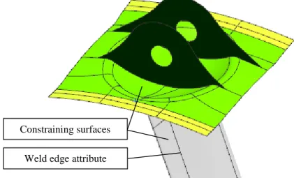
The key property of the assessment module is selection of CAD features to be analyzed. A single DC is opened in NX interface and specific attributes are selected with the help of internal KF applications (Fig. 4). The attributes are simply selectable model edges which are regarded as weld edges. Surfaces surrounding the weld edge are constraints and have to be selected in order to correctly evaluate reachability data of the weld. This enables a sort of reachability metric estimation by providing information about weld edge surroundings such as nearest collisions restricting the welding mechanism. These features are then automatically sent to the excel file and additionally grouped to define how they are welded together.
Figure 4 Model feature example
Collect CAD data is the second process part which uses assessment definition
input for CAD data extraction. Here, previously mentioned features’ file is updated with CAD data through the script which opens each DC, applies specific KF rules and extracts metrics like length, curvature, material ID, thickness, reachability angle and distance. Not all the data is directly available in the NX application and therefore it must be derived by automatically implemented model manipulations, which are the major cause of time extensive process. To simplify the work, no new files are generated at this point as necessary data is retrieved and stored directly into the same input file, which can then be used for data analysis directly.
Weld edge attribute Constraining surfaces
Introduction
Data evaluation is the final part of weld producibility assessment system where it
is processed by a python script to structure and evaluate it against process plans and weld methods defined in the initial part. Established form of evaluation output provides a complete summary of all features for the entire set of DCs with some of the data expression handles, i.e. summation, max/min values, number of occurrences etc.
Current state of the system raises several requirements for its successful execution stated in the previous research findings [4], i.e.
1. Strict naming convention – feature names are crucial for the system to differentiate between features and identify if an attribute is a weld.
2. Feature sustainability – it is important to make sure that the evaluated features are maintained in the geometry.
1.1.5 Turbine Rear Structure
Turbine Rear Structure (TRS), Turbine Exhaust Case (TEC) and Turbine Rear Frame (TRF) are all the names referring to a rear end static component of the jet engine (Fig.5). It supports low-pressure shaft and redirects exhaust flow from low pressure turbine to the exit nozzle [14]. This structural part is used as a case study object for producibility assessment because its complexity better corresponds to the development level of the producibility system. However, it is recognized that a fully developed automated producibility assessment platform should be able to maintain robustness for a wider range of structural components than just TRS.
Figure 5 Turbine Rear Structure (highlighted) [15]
The benefit of TRS as a case study object also lies in its concept which is driven by manufacturing and purchasing rather than product functionality. Nevertheless, it still does not diminish structural requirements to withstand thermal, structural loads as well as to be light and aerodynamic for fuel efficiency [14, 15].
Low pressure turbine
Low pressure shaft
The parts used to assemble TRS are cast, forged or formed from sheet metal. Before the parts are welded together some machining operations are carried in preparation for the assembly and afterwards to deliver with the right geometric tolerances [15]. Finished structures are carefully inspected using various methods focusing on weld seam quality and other features.
1.2 Purpose and research questions
The object of this study is producibility assessment and how its multi-disciplinary analysis can be improved with manufacturability aspects for the proposed set of DCs. The project is performed at the aerospace company and therefore executed in the existing environment of that company where multi-disciplinary analysis system is represented by EWB and weld producibility assessment system is under development. Although implications of this research may be discussed outside the case of execution but the research questions formulated are in the context of models and tools provided by GKN Aerospace Sweden.
Weld producibility assessment system is under-developed and therefore not yet integrated into EWB. Some functionalities are finished but they are not formally validated. Assessment definitions require extensive investigation to accurately determine and define welding process in terms of time and costs. However, such accurate assessments are outside the scope of the thesis. Therefore, the first research question is focused on the data that is already attainable in the system and is formulated as such:
How can CAD model data be used for weld producibility assessment in a meaningful way? Multi-disciplinary studies are performed to observe potential design trade-offs between different parameters. Similarly, it would beneficial to be able to evaluate all producibility indicators and determine their impact on production. Then, one would be able to know what to focus on to improve producibility and by how much in a quantifiable manner:
What are the most influential producibility indicators and how do they compare?
To conclude any design with an overall producibility evaluation, there must be a way to express different indicators into a unified measurement. For the business, such ultimate measurements are time and costs, which are difficult to accurately predict and acquire. Here, general process plans are investigated to see if the influence of different indicators could be determined and used to find a unified form of assessment:
How can producibility indicators be summarized to a single form of measure?
1.3 Delimitations
The work is largely based on already available but underdeveloped weld producibility assessment system which requires specific expertise in the
Introduction
The scope of the project is rather large and includes input not only from design but also from production specialists. Here, multiple aspects in production processes are reviewed but not thoroughly investigated and had to be represented in the system with subjective assumptions based on discussions with company specialists. Therefore, resultant data does not show definitive assessment of the case study object but rather allows to see what the data could look like and what conclusions could be made.
1.4 Outline
The thesis introduces several relevant concepts in its theoretical background to better understand where the project stems from. Then a big focus is put on methodology and its selection followed by implementation. Afterwards, the results are shown and discussed along with methodology. Lastly, conclusions are drawn based on established research questions and suggestions for future work are made.
2 Theoretical background
This section explains theoretical background of the thesis. It introduces and discusses several relevant definitions and concepts which were also addressed by the preceding works of the project.
2.1 Knowledge-Based Engineering
To fully grasp the essence of this thesis research environment, several design engineering concepts need to be re-stated and further discussed. It is explained how traditional design engineering differs from Design Automation (DA) below. Conventionally, a typical design engineering process involves moving from stages of preliminary towards detailed CAD model, which is finalized to meet objective criteria stated in the beginning of product conceptualization phase. Such traditional process can be facilitated with an innovative approach in computer-aided engineering known as Knowledge Based Engineering (KBE). KBE is defined as: “…a method which captures product and process-based data and helps in building a virtual prototype in a system <…> for building a geometric model along with downstream processes such as material selection for static and dynamic analysis, and manufacturing capability enabling design automation.” [16].
KBE allows design automation to take place by storing and retrieving design related data. The data can be used to automatically generate new models avoiding repetitive design tasks. Realistically, such concept implementation and use requires substantial support of computer based solution principles. Artificial Intelligence (AI) structures can be utilized, which are further theoretically discussed in Heikkinnen & Müller, 2015 [3] preceding project work. Nevertheless, well implemented knowledge-based systems should not be difficult to modify as the knowledge stored within is defined explicitly [17]. Therefore, one could, to some extent, work with the system without extensive knowledge of the programming language used. That is why some system manipulations and amendments were performed in the execution of this thesis.
Here it is important to understand that KBE, as stated by Rocca, 2012 [18]: Automates repetitive and non-creative tasks.
Supports multi-disciplinary design optimization in all design process phases.
2.2 Set-Based Concurrent Engineering
It can easily be shown that product development involving several different objectives in its realization can become a very complex task, especially when parameters defining those objectives are not directly correlated. How does one then must undergo a development process?
Theoretical background
Set-Based Concurrent Engineering (SBCE) is an engineering methodology with the potential to be applied not only in the development but in business activities in general because it seeks to address different process tasks in parallel or at the same time. So by reducing sequential work this concept results in reduced lead times and, consequently, costs.
The problem related to sequential development process is very well represented in the Figure 6, a. Here, the impact on the product life-cycle costs as early as in the concept development stage is shown to have the biggest influence as the information about the product in those early stages is mostly lacking. Initial poor judgment can cause re-design loop-backs which drive the costs even higher. In the sequential process, up to several stages may have to be repeated if they end up in that re-design loop. Latter situation is named as “over the wall engineering”. One must consider multiple product development stages concurrently to avoid re-design issues, e.g. manufacturing is addressed as early as in the conceptual studies. This, of course, is no re-design proof method as development is always an iterative process but the number of changes, time and costs can be significantly reduced (Fig. 6, b).
Figure 6 Engineering decision making impact and concurrent engineering benefit [19]
Another aspect of SBCE allowing the processes to be worked on concurrently is a set-based approach. Contrary to the point-based approach, where only single or few Design Cases (DCs) are considered, set-based concept involves exploring a wide design space. The number of infeasible solutions is reduced only as exploration of design space continues. Most importantly, all the design cases are a valuable source for the previously presented knowledge base system, where their information is stored. This allows going back to them and using the obtained knowledge to look for relations of different parameters. Exploration of the design space lets developers find a more optimum solution and reduce loop-backs since alternative DCs can be selected without significant development efforts at any stage. Subsequently, SBCE studies have shown reduction in probability of design iterations [15].
2.3 Design of Experiment
Design of Experiment or DoE is a statistical method to define performance of a system by looking for correlation between input and output variables [20]. This method is the most general approach that one can employ to evaluate a system as it looks at it from a “black-box” perspective. It means that no assumptions are initially made and the system is regarded as unknown. It is acknowledged that the system is subjected to factors and can give an output when acted upon by an input (Fig. 7). Varying a set of input parameters, system’s behavior can be constructed and mathematical response surfaces can be plotted.
Figure 7 Formal definition of DoE [20]
In the most common scientific sense, the experiments are carried out by selecting one single variable while fixing the rest. Then, with enough certainty, observed response could be concluded to be a direct outcome of that variable. Nevertheless, multi-variable analysis is common in the DoE which then has to employ mathematical statistical models to vary those sets of parameters. In fact the increased variation in the design of computer experiments is an objective as it covers a wider design space and explores it by evenly spreading parameters across it [3].
Without resorting to extensive mathematical explanations of DoE distribution, the key take away of this chapter is to grasp the intent of the concept. It plays an important role in SBCE and is directly used to generate series of design case models by applying DoE on a single parametric base-line CAD model.
2.4 Manufacturability Assessment System
Manufacturability Assessment System or MAS is a system of tools which allows predicting or evaluating how manufacturable is a specific product design. Such system is exactly what is desired to be integrated into product development process.
Theoretical background
Despite rather intuitive definition, it is important to clarify the distinction between the terms manufacturability and producibility. Vallhagen J. et al. 2013 in his research about producibility and manufacturability methodologies for the development of aerospace engine components said that manufacturability is used in the context of producibility. There is a clear distinction between the two terms. Producibility holds a strong link to product functions and performance, whereas manufacturability only focuses on product manufacturing trying to make it easier with less regard to product performance [21].
Therefore, MAS can be a system on its own as a subset of a broader producibility assessment system, where product performance and other characteristics are considered together with manufacturability. It is also concluded that in an aerospace context product functionality is so critical that there is a strong performance bias [10] which means that manufacturability tends to fall into a category of secondary influential factors. This by no means suggests that it could be neglected as it still is a valuable support to optimize objective design.
MAS usually employs such tools as Design for Manufacturing (DFM) and Design for Assembly (DFA). The concepts solely seek to design the product in a way to improve its manufacturing by reducing the number of assembly parts and modeling the product to allow more preferential manufacturing techniques. In the context of high end technology engine components, tools like DFM and DFA may be more limited due to functionality based product design constraints.
It would be best if CAD/CAM systems supported MAS as much as possible which would allow highly automated assessment process. Some modern computer modeling software already have built-in systems with enough flexibility for a user to create, customize and apply DFM rules to their design cases and extract relevant data. The data can be directly used as an assessment or joined with externally available techniques and pre-established knowledge base to analyze it. For example, information like material type, sheet thickness, minimum corner radius shapes and dimensions of holes could be extracted from the models. Then this information is used as inputs to the MAS. Generated outputs can be redesign suggestions, selection of processes and materials, process sequencing setups, planning setups and even foreseeable production costs and times [22]. Here, production costs and times would be ultimate complex indicators obtained from collective geometry metrics used as inputs. Intermediate indicators can be post-processed by MAS to define not just the overall influence on the costs or time but on parts of production too, e.g. inspectability.
The challenge is that manufacturability metrics and their effect must be well internally defined which requires sufficient knowledge of the involved manufacturing processes. To succeed, developers and production specialists have to cooperate. Afterwards, the knowledge base can be created which contains all the necessary manufacturing rules and figures. It is also important to recognize that MAS must be constantly updated to stay current with the changing manufacturing processes.
2.5 Production costs and time modeling
The ultimate objective in producibility assessment for business is defining product prototypes in terms of process time and costs. This is a very challenging objective involving a lot of controllable and uncontrollable factors. Here the most relevant aspects of welding assessment are reviewed.
It is found by Miller D.K. (2004) that when it comes to welding costs, there is a number of factors that could be considered, e.g. [23] time for joint preparation; time to prepare the material for welding (blasting, removal of oils, etc.); time for assembly; cost of electrodes; cost of shielding materials; cost of electric power etc. There are three basic approaches to estimate welding costs, i.e. costs per unit, length or weight. The approach can be chosen based on the manufacturing type. Unit method applies for pieces moving through a workstation, length is used for estimating long continuous welds and weight method works for significant volumes of weld material deposition.
Pabolu V. et al. (2016) [6] investigates welding manufacturability of TRS and chooses price per weld length approach to model the costs. The calculations are made based on chosen weld method, joint filler material, length of weld, number of welds and the average weld speed. Used modeling approach is relatively detailed and tries to express weld length costs in terms of fixed costs, i.e. equipment, installation, maintenance etc. and variable costs, i.e. manpower, electricity, filler material etc. Such costs modeling method assumes fixed and variable costs to be constituents of the total costs expressed per weld length unit. However, given discussed weld length approach does not explicitly define the most impactful design aspect affecting the costs. One could not decide that the most effective way to reduce costs is a weld length reduction simply because they are expressed per unit of length. Latter assumption is one dimensional and overlooks complexity of the estimations where product design changes for the same weld length can carry immense hardly predictable manufacturing effect. Therefore, discussed estimation method does not allow costs and production time optimization because indicators of highest influence are not identified. Here, product design must be considered in relation to manufacturing to establish valid impact evaluation.
Reviewed theory explained the importance of design automation, the benefits of set versus point-based design and a way to explore design space relying on DoE. Such analysis approach can be implemented into MAS which includes different design cases as input data, knowledge-base as analysis module and output. The challenges associated to resultant system’s indicators, i.e. costs and time modeling were discussed considering preceding works of the project. It was emphasized that
Method and implementation
3 Method and implementation
This chapter is focused on method selection and implementation plan to execute the thesis. Two general methods used in the preceding works within the topic are described and compared to set the preference.
3.1 Design Research Methodology
As mentioned in the section 1.1, producibility assessment development follows Design Research Methodology (DRM) established by Blessing and Chakrabarti, 2009 [8]. The method aims to clarify research objective by introducing concrete success criteria. Here it is analyzed what are the main factors preventing successful research and how can they be worked on to achieve success.
It has been mentioned that this thesis work is a sub-part of a broader DRM scope consisting of four main executable steps. Several previous works leading up to this thesis used DRM as the main method for their smaller scope research showing that the method can be applied on different scalability levels. Below it is briefly summarized what is the essence of the method to fully grasp the context of this thesis. Later it is argued whether the same DRM should be applied here.
The goal of DRM is built on three major questions, i.e. “what is meant by successful product, how is a successful product created, how can the chances of being successful be improved?” [24]. Such fundamental approach allows to define research objective, factors affecting research success and how obtained knowledge can be used to create design support to determine whether its application leads to successful results. The same characteristics are embedded into methodology structure composed of four part described below.
Research clarification
It is important to begin with research clarification as the first DRM step is to define success and introduce measurable criteria. This is a fundamental element of the method identifying the aim of the research, focusing upcoming studies to find what is preventing success, developing support aimed at addressing the most influential factors and allowing its evaluation.
In the broader project scope that this thesis contributes to, it is desired to introduce a functioning producibility assessment system into multi-disciplinary set-based concurrent engineering studies. Some relevant success criteria that are impacted by this thesis are reflected in previously carried case studies by Elgh F. et al., 2016 [5]:
Time spent in project - measured in time
Support the designer - measured by designers’ assessment
Lower number of errors - measured by number of changes in series production
Descriptive study I
In the first descriptive study it is necessary to increase knowledge and understanding of a design determining the most influential factors affecting established measurable criteria. This creates basis for the design support to be developed on.
At GKN, the first descriptive study knowledge has already been gathered by mentioned producibility assessment system research and development contributors. Some of it is available in their publications but additional information was collected from company staff assisting this thesis work.
Prescriptive study
Prescriptive study uses results of the descriptive study to develop an impact model which describes improved situation, systematically develops support and evaluates it. Here it was not required to develop a fully functional and complete impact model design. It only had to be enough to evaluate support with respect to previously established success criteria. Therefore, prescriptive study is usually a type of demonstrator or prototype which can later assist in a more complete development of the system.
Producibility assessment system is the impact model and, although under-developed, it is the main working object of the thesis. The project is set in the prescriptive study phase of DRM which activities according to Blessing L., 2004 [25] can be summarized as such:
Impact model or theory development. Systematic support development.
Support evaluation with respect to its in-built functionality, consistency, etc.
The thesis contributes to all three summary points because it is aimed to assess the current impact model required by the study, implies systematic changes to collect relevant producibility assessment data and supports evaluation of the system as a whole by evaluating used indicators obtained from it.
Descriptive study II
The final study of DRM is focused to evaluate and validate the outcome of the prescriptive study and looks at it from a study purpose point of view. This can lead to some qualitative and quantitative results as established measurable factors should be evaluated.
Method and implementation
Method feasibility for the study
DRM is known to be a good fit general approach method when it comes to determining which research to conduct and conclude it with specific measurable criteria evaluation. However, DRM process suggests method application to find and research innovative solutions when the working environment is not well known and requires lots of information collection. As many research methods, DRM is an iterative process during which different studies may be re-evaluated and considered concurrently. The method seems to be scalable if several impact models are determined in the study and considered separately. For example, if the PAS was to be complemented with other assessment tools besides weld producibility, they could be researched individually. Nevertheless, Goldkuhl G., 2013 based on other scholars’ publications, reviewed that DRM operates on a general level. He noted that the impact model design, although pursued on a specific problem, is later abstracted to a class of problems [26].
On the other hand, this thesis is focused on PAS and attempts to at least partially introduce it to the multi-disciplinary design studies. No new complete system was developed and only the most indispensable amendments were made in the existing system to allow the study.
DRM is very much focused on the technological view of a developed IT artifact and has little attention on how it is shaped by organizational context [27]. This property is conflicting with the research objective where systematic development was only a consequence to approach producibility indicators evaluation.
Consequently, DRM method was not employed in the study as most of the required information is readily available for the defined research objectives yielding Descriptive Study I rather irrelevant, if DRM was to be applied. The most influential factors prohibiting the study are linked to the available weld producibility assessment system and were solved internally without extensive discussion in this thesis.
3.2 Action Research
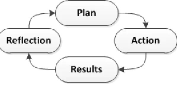
Methodology employed in the thesis is Action Research (AR) which is concerned about improvement through action [28]. The method is better recognized in social sciences but was applied by Pabolu V. 2015 [6] in weldability analysis system development who chose the method over DRM as well. Nevertheless, AR can be employed in both quantitative or qualitative researches and focuses on local practices without overlooking its contribution to the general study [25]. The method is iterative and involves repetitive reflection on action cycles to verify if produced results or study refinements are needed. AR is a process by which change and understanding can be pursued at the same time [29]. Therefore, it was a sufficient approach for the study as it was not clearly known which indicators and in what form were to be analyzed due to potential delimitations imposed by the system.
Action Research was also discussed in the research methods literature review by Runeson et. al. 2009, who discussed AR application in software engineering stating that the method can be used in combination with case studies to better determine pre-and post-research impact [30]. Finally, AR is simply preferable due to its relevance to the project underlined in method definition: "the AR approach … is particularly appropriate for solving problems for which past research has provided, at least a starting point and for the time being, a reasonably accepted scientific model supported by evidence. AR can then test the evidence against the model, refine it, or improve on it" [31].
Above exactly corresponds to the project scope as some previous research has already been made. It was important to focus on the output of the system available evaluating its robustness through a case study and in turn doing some possible and necessary refinements imposed on the system.
Finally, the key characteristic shared both by the method and the project is active researcher and clients or participants collaboration which allows bringing together general theories and situated, practical knowledge [32]. The participants in this case are company specialists closely related to investigated issues.
Figure 8 Action research cycle
Although typical AR steps consist just of four parts, i.e. plan, action, results and reflection (Fig.8), they can be detailed and split into six method execution steps [6, 33]:
1. Identifying the problem(s).
2. Analyzing the problem(s) and determining some relevant casual factors. 3. Formulating tentative ideas about the crucial factors.
4. Gathering and interpreting data to sharpen these ideas and to develop action hypotheses.
5. Formulating action(s).
6. Evaluating the results of the action(s).
These AR method steps were adapted to the study of the thesis and their implementation is elaborated next.
Method and implementation
3.3 Application of research method and implementation
In this section previously discussed and selected research method is detailed for implementation. The process following methodological Action Research steps is clarified explaining how the project was carried all the way to the evaluation of the results.
3.3.1 Problems identification
Having reviewed previous works in producibility assessment system’s development, it was recognized that this research also deals with the same topics, i.e. robustness, flexibility and assessment meaningfulness. To make the solution impactful, problems related to producibility assessment had to be detailed and understood. This aided not only as a research guiding tool but allowed to get back to the issues stated to evaluate project success.
Relevant problems were identified by the work supervision at GKN: Current state of producibility assessment system is not known.
Some obtained data is incorrect and systematic problems are yet to be solved.
Although a framework is established, data post-processing needs further development.
It is not clear what types of producibility aspects are relevant in the production.
It is not completely known how or in what form producibility assessment geometry metrics can be translated into meaningful indicators and introduced to multi-disciplinary design studies.
More producibility assessment indicators are to be obtained and it is not known what implication they pose on the system.
It is not clear how producibility indicators could be used to assess weld process plans and their preliminary time and costs.
3.3.2 Analysis of problems and relevant factors
Previously gathered project based problems were analyzed to determine relevant work execution factors.
The issues seemed to involve extensive work within the system testing it and working with data. This is because it was initially recognized that systematic errors had to be found and worked out to even make the study feasible. Clearly, ability to handle the system and knowledge about its way of execution was imperative to study success. Consequently, latter requirement yielded some factors to be hardly controllable, i.e. if the error found is not completely amendable to the best of author’s capabilities.
The next focus area to allow project execution was data post-processing. For a completely realized system, a robust automated post-processing module was required. Here, many things had to be considered because post-processing would be integrated in the weld producibility assessment system. Automation of this module was highly preferable even for the limited case of this study as several cycles of data extraction had to be performed. This could be very time consuming if each data processing attempt was to be done manually. Therefore, post-processing structure, data input and readability for automated analysis were considered.
The problems seemed to be linked. For example, more producibility indicators needed to be identified but their implementation may have posed changes to the preceding parts of the system like data extraction or post-processing. Therefore, it was important to tackle the tasks concurrently and receive feedback continuously. Production input was used to concentrate on indicators’ relevance and data visualization. It was important to establish clear mutual understanding between production and product development to really address the key metrics translatable into meaningful indicators.
Based on identified problems, it became clear that the study with the main goal to evaluate performance and impact of the producibility assessment system is multi-objective. The key factors of the study are initial study setup, system’s modifiability, data input, post-processing structure, indicators and their relevance.
3.3.3 Tentative ideas for execution
Once the problems were gathered and analyzed, it was possible to state ideas for project execution. The focal points of the study implementation are revealed below.
Current state analysis and setup
To perform current state analysis, a close practical familiarization with the weld producibility assessment system was required. It was first observed how the system performs on the simplified design cases like the ones it had been developed and tested on in the previous works. Then obtained metrics, i.e. length, material ID, curvature, reachability distance and angle were carefully evaluated for the welds of the case study object.
Case study models were TRS CAD assembly DCs used to evaluate several different weld groups. Obtained metrics were evaluated and encountered problems preventing execution were identified. Necessary modifications to the system were made to verify that resulting metrics are correct.
The outcome of the study setup was to identify any points of concern in later studies and possibly improve system’s performance. This was realized by adapting the system to handle TRS models. As a result, application of the system could be
Method and implementation
Post-processing development
Post-processing is an extension of weld producibility assessment system which takes resultant geometry data from the system and reconfigures it into meaningful data for producibility. It was certain that this module may have required additional input as indicators are usually based on production definitions, which have to be obtained as well. It was not intended to develop a fully functioning system so the way that post-processing is linked to other data sources may not follow systematic design practices used in the previous works.
Nevertheless, post-processing was fed with data several times during this study so process automation was preferred to speed up iterations and minimize manual data handling. Here, the success of post-processing development was mostly dependent on the software selection and capability to work with it.
Well-developed post-processing module should speed up data preparation for results visualization and integration with overall multi-disciplinary design data, which is later used to investigate parameter relations.
Production input
The project was evaluated based on the feedback from production and development specialists regarding demonstrated results of the system. Therefore, it was useful to rely on the same people to steer the project into the right direction.
Production input was required several times during post-processing development stage. This is because potential indicators were formulated first and then proposed and discussed with the production. The feedback was used to exclude or modify indicators gathering additional information. The communication was carried during project status updates to collect feedback.
This step had an effect both on system’s setup to do modifications for additional data retrieval, and post-processing module to adjust data handling.
Preliminary project execution plan
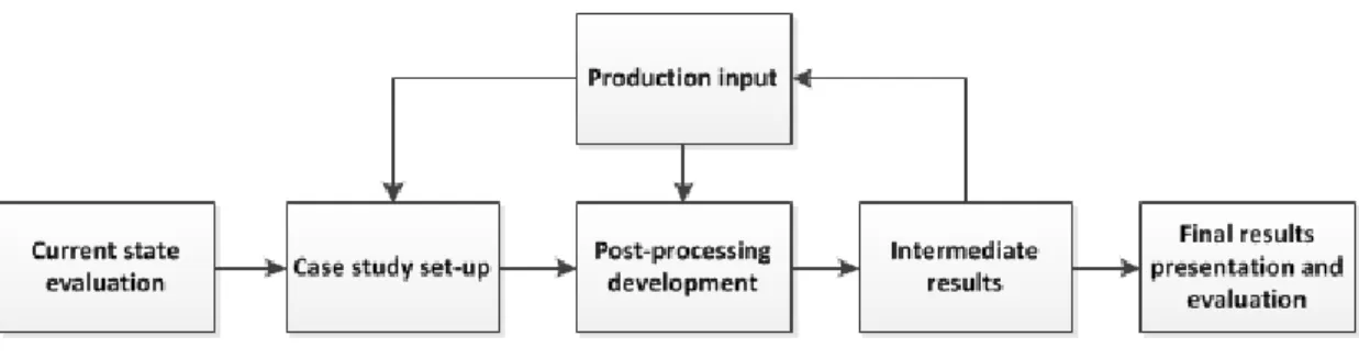
Above execution ideas were summarized and presented in a preliminary project realization plan (Fig.9). Some aspects of action research methodology were already taking shape since production input may be regarded as a reflective part of the project requiring several research iteration cycles.
To sum up, some familiarization in current system’s state evaluation was obtained to move on to the case study setup where all imperative systematic amendments were made to proceed with the project. Then, post-processing module development started, intermediate results were collected and refined with production input. Lastly, results were presented and evaluated to determine the impact of the study. Execution steps and final data evaluation are described next.
Figure 9 Preliminary project execution flow
3.3.4 Gathering and interpreting data to establish first action plan
It was first necessary to start working with the weld producibility assessment system to gain practical familiarization and evaluate its current state. That is why the title of this section implies preparation for the study leading up to the actions taken to achieve the research objective.
Design cases studied
The focus in this research step is already mentioned TRS (Fig.10) component of a jet engine. Case study models from the previous EWB analysis were provided. They follow pre-defined DoE setup for 29 DCs with varying model parameters. Once the assessment took place, these variations had to be reflected by the weld producibility geometry metrics.
TRS is a welded assembly of different structural parts. Each available DC consists of:
MNT – 3 mounting sections
MRT – 2 mounting transition sections
REG – remaining number of regular sections
Sections can also be interchangeably referred to as struts, vanes and sectors. MRT indicates how and where TRS is mounted to the other engine components. These sections are therefore sturdier than the others. MRT is a transition section between MNT and REG. Consequently, faces of MRT are thinner than MNT but thicker than REG.
Method and implementation
Figure 10 Turbine Rear Structure (TRS) single DC
While MNT, MRT section number is always the same for the DCs, REG section number is varied. Another variation parameter related to struts is their lean angle. In the case study there are multiple TRS models with different combinations of section numbers varying from 10 to 16 and lean angle increasing from 0 to 40 degrees (Fig.11).
Assessment study was prepared with the help of project supervision at the company selecting weld edges of interest, i.e. Outer Case (OC) edges separating the sections, HUB welds enclosed in the air flow cavity and flange rings supporting cylindrical structure from both sides.
Figure 11 Structural variation across DCs (DC7 – left, DC18)
However, not everything is reflected by the DoE and CAD models for various DCs. To maintain stiffness for the DCs with 13 or fewer struts, additional welds are introduced. In fact, between each section an additional plate is welded in to stiffen the structure. Consequently, it was recognized that different production rules may come into place based on study setup and these rules too have to be accounted for in the weld producibility assessment data.
Sectors no: 10 Lean angle: 0o
Sectors no: 16 Lean angle: 40o
Validation and errors traceability
There are two main sources of errors in weld producibility assessment, i.e. model and/or the system itself. Therefore, data validation for the weld producibility assessment system was performed in two ways:
Checked manually in the NX application – reveals system errors. Looking for inconsistencies throughout all data – reveals model errors. Manual checking in the NX application was done employing built-in measurement tools, e.g. edge length, curvature analysis etc. If compared data agrees, it could be concluded that the system assesses CAD model correctly. Otherwise errors may be found in analysis setup or within execution scripts of the system.
Manual data validation is highly supported by knowledge gathered in the previous part where design case study models were discussed. Since it was known how the structure is varied, consistencies for some of the different weld groups could be assumed. For example, OC welds have the same length, therefore, it was sufficient to only check one metric value per DC and look for changes in equivalent weld groups. If inconsistencies were found, then they could indicate a model related error.
Such validation approach addressed previous development project of the system where the importance of correctly setup CAD models is emphasized.
Amendment of the system
Perhaps the most important part of the case study was not just to evaluate the system but to gain knowledge on how it works. Running into systematic errors and attempting to amend them increased understanding about the system and how it is executed by scripts programmed in VBA, KF and python. It was recognized that modifications to the system are most certainly needed to make the study feasible. Consequently, knowledge and ability to work within it was essential for successful system’s extension and data post-processing. Therefore, to speed up the process, all imperative amendments were performed with the help of department support.
3.3.5 Formulating actions Action cycle 1: Data post-processing
The most important task after successful systematic setup was the post-processing of the obtained results. At this point enough knowledge was available based on previously gathered information to handle data and establish meaningful indicators.
To maintain systematic integrity, post-processing had to be an extension of the weld producibility assessment analysis module. For mere demonstration of the
Method and implementation
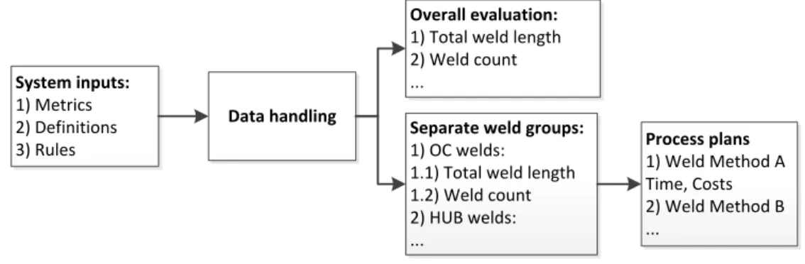
Additional inputs for the system were considered too because geometric CAD model data alone cannot fully define producibility assessment. It was discussed previously that EWB is interconnected where several disciplines depend on one another. If producibility assessment gets integrated as an equivalent module, then it too may have to consider inputs from other disciplines. All additional data such as relevant rules not reflected in the CAD data were regarded as inputs as well (Fig.12). The last part of established data post-processing was process plans where preliminary time and costs are intended to be defined for different welding methods. Investigation of the process plans is further explained in the 3rd action cycle. System inputs: 1) Metrics 2) Definitions 3) Rules Data handling Overall evaluation:
1) Total weld length 2) Weld count ...
Separate weld groups:
1) OC welds: 1.1) Total weld length 1.2) Weld count 2) HUB welds: ... Process plans 1) Weld Method A Time, Costs 2) Weld Method B ...
Figure 12 Data post-processing
Post-processing implementation is a cyclic process where system’s development and testing requires several iterations. Such system is also prone to continuous changes due to varying range of manufacturing inputs and their values. Subsequently, a semi-automatic data post-processing module solution was approached admitting that a full automation would be a wasteful and tedious task before the impact of the system is even demonstrated and evaluated.
Action cycle 2: Investigating process plans
The next implementation step required in the post-processing module was process plans analysis to determine manufacturing resourcefulness. Here, resourcefulness implies some sort of unified assessment criteria considering that definitive manufacturing time and costs are not attainable within the scope of this research. Process plan’s module is a part of the assessment definition within the weld producibility assessment system and includes different weld methods (Table 1). Only incomplete framework was available without sufficient manufacturing consideration to establish measurement rules. Therefore, process plans were investigated in attempt to:
Expand process plans analyzing TRS manufacturing.
Find and demonstrate preliminary time, costs or other unified measure based on available metrics for this study.
Considering cost modeling limitations of Pabolu V. 2016 [6] discussed in section 2.5, where he tries to evaluate all fixed and variable costs to express them for weld length, a different approach was taken. Instead of approximating production costs in terms of fixed and variable inputs, it was tried to find out what additional manufacturing resourcefulness comes from design changes. The intention was to relate product design to its manufacturing implications through available metrics and indicators. Therefore, production platform documentation for a sample 10 sectors TRS model was used with foreseen production times estimated. The data was discussed with a process engineer during meetings and production floor visits. Table 1: Process plan template for different weld methods
Indicators 1
2 … n
Methods Laser Beam Weld Tungsten Inert Gas Weld Plasma Weld Electron Beam Weld Process plans
Tackweld Tackweld Tackweld Tackweld Machining Machining Machining Machining Inspection Inspection Inspection Inspection
… … … …
Time … … … …
Costs … … … …
Once the list of process plans was expanded, each operation was considered with respect to its manufacturing impact and involved producibility metrics, i.e. length, thickness, curvature, material ID, reachability angle, reachability distance. Such analysis allowed capturing more process items to be added and possibly rules for their assessment.
Action cycle 3: Metrics and indicators visualization
It was not sure that CAD model assessment metrics would lead to an increase of captured indicators. However, it was sufficient that these metrics and indicators could be used to rank DCs within their categories. Afterwards, extreme cases could be depicted depending on their max/min values, e.g. long weld length DCs were less preferable then shorter weld length DCs based on that single evaluation category.
Once data meaningfulness was realized, it was possible to visualize and interpret it. This could be achieved using different tools. Most conventional and known to the majority of employees is MS Excel where tabular data can be quickly graphed on chosen chart types. The company also uses powerful optimization tool software - modeFRONTIER for multi-objective and multi-disciplinary optimization. For the case study this software was utilized to plot response surfaces of gathered geometry data to be assessed because several interpolation and extrapolation options are available within it.
Method and implementation
Action cycle 4: Response demonstration of producibility assessment indicators
After data post-processing and visualization was possible, demonstration of producibility assessment indicators could be prepared. All design cases were summarized and their data fed to the overall EWB multi-disciplinary analysis summary table. Here, results demonstration of potential system in action is called a demonstrator.
Following EWB structure, producibility assessment data is supposed to be introduced as an additional discipline with its indicators to the multi-disciplinary results table (Table 2). Selected indicators were used to reflect both overall and separate evaluations from the data post-processing. This allowed analysis to take place on overall and separate producibility assessment level.
Table 2: General EWB results table outline
To determine how data interact with each other, a correlation matrix was created. Correlation matrix is a table which header rows and column consist of all investigated inputs and outputs and their correlation is evaluated by the cell values in the table. Only the most relevant data from other disciplines was taken to observe its response. Correlating and other parameters of interest were visualized and discussed.
3.3.6 Evaluation of actions’ results
It would have been a too extensive research to figure out how proposed working system affected design during a full development life cycle and gather quantitative data like reduced number of re-design loops or generated savings. However, a well-developed demonstrator of the system’s performance could be used as a reflection of the actual system in action. Therefore, this evaluation was focused on company specialists involved in development and manufacturing to determine what is their view on the results presented. Used questionnaire can be found in Appendix A.
Finally, to verify overall thesis success, identified problems laid out in the beginning of the methodology implementation (sec. 3.3.1) were discussed as well.
DCs Sections Str u ctu ral A e ro d yn am ic Th e rm al … Producibility Indicator 1 Indicator 2 … 1 16 … … … 2 16 … … … … … … … … 29 16 … … … Min … … … Max … … …
4 Findings and analysis
This chapter concisely presents findings and analysis of the research whereas its evaluation and discussion is presented separately in the following chapter. Here, covered topics include assessment setup, producibility metrics and indicators, developed data post-processing analysis, investigation of the process plans and results demonstration.
4.1 Assessment setup
During the setup of the system for TRS producibility assessment, available CAD model metrics had to be verified. This revealed several systematic obstacles and confirmed initially stated requirements for the system’s performance.
It was found that each CAD model contains edges of two types, i.e.
Single edges – one edge identifies separation between two faces to be welded, e.g. vanes (Fig.13, red)
Double edges – two identical edges shared by two faces which are associated to them respectively, e.g. outer case (OC) edges (Fig.13, blue). In the figure one group of MNT edges belongs to the left section and the other to the right.
It became clear that assembly models usually have such edge types. Single edges are simply added on the face to identify potential weld. Double edges are not explicit and come from the way the model is built, e.g. separate OC sections used as CAD building blocks. The system is not able to distinguish between the types and gives two times higher values for length data when working with double edges. This was not fully resolved systematically and had to be taken into account during post-processing.
Single edges Double edges
![Figure 1 Project’s scope (selected) within Design Research process framework [8]](https://thumb-eu.123doks.com/thumbv2/5dokorg/5437963.140499/9.892.195.701.104.450/figure-project-scope-selected-design-research-process-framework.webp)
![Figure 3 General system architecture of weld producibility assessment [4]](https://thumb-eu.123doks.com/thumbv2/5dokorg/5437963.140499/11.892.165.738.660.1001/figure-general-architecture-weld-producibility-assessment.webp)
![Figure 5 Turbine Rear Structure (highlighted) [15]](https://thumb-eu.123doks.com/thumbv2/5dokorg/5437963.140499/13.892.210.685.647.975/figure-turbine-rear-structure-highlighted.webp)
![Figure 6 Engineering decision making impact and concurrent engineering benefit [19]](https://thumb-eu.123doks.com/thumbv2/5dokorg/5437963.140499/17.892.142.759.518.728/figure-engineering-decision-making-impact-concurrent-engineering-benefit.webp)
![Figure 7 Formal definition of DoE [20]](https://thumb-eu.123doks.com/thumbv2/5dokorg/5437963.140499/18.892.256.646.325.532/figure-formal-definition-of-doe.webp)