M
ÄLARDALEN
U
NIVERSITY
S
CHOOL OF
I
NNOVATION
,
D
ESIGN AND
E
NGINEERING
V
ÄSTERÅS
,
S
WEDEN
Advanced Project in Computer Science, 30 ECTS
A
TOOL
-
SUPPORTED METHOD FOR
FALLACIES DETECTION IN PROCESS
-
BASED
ARGUMENTATION
Laura Gómez Rodríguez
lgz17001@student.mdh.se
Examiner:
Barbara Gallina
Mälardalen University, Västerås, Sweden
Examiner:
Radu Dobrin
Mälardalen University, Västerås, Sweden
Supervisor: Faiz UL Muram
Mälardalen University, Västerås, Sweden
Abstract
Process-based arguments aim at demonstrating that a process, compliant with a standard, has been followed during the development of a safety-critical system. Compliance with these processes is mandatory for certification purposes, so the generation of process-based arguments is essential, but also a very costly and time-consuming task. In addition, inappropriate reasoning in the argumentation such as insufficient evidence (i.e. a fallacious argumentation), may result in a loss of quality of the system, leading to safety-related failures. Therefore, avoiding or detecting fallacies in process-based arguments is crucial. However, the process of reviewing such arguments is currently done manually and is based on the expert’s knowledge, so it is a very laborious and error-prone task.
In this thesis, an approach to automatically generate fallacy-free process-based arguments is proposed and implemented. This solution is composed of two parts; (i) detecting omission of key evidence fallacies on the modelled processes, and (ii) transforming them into process-based safety arguments. The former checks automatically if the process model, compliant with the Software & Systems Process Engineering Metamodel (SPEM) 2.0, contains the sufficient information for not committing an omission of key evidence fallacy. If fallacies are detected, the functionality provides the proper recommendation to resolve them. Once the safety engineers/process engineers modify the process model following the provided recommendations, the second part of the solution can be applied. This one generates automatically the process-based argument, compliant with the Structured Assurance Case Metamodel (SACM), and displays it –rendered via Goal Structuring Notation (GSN)– into the OpenCert assurance case editor within the AMASS platform. The applicability of the solution is validated in the context of the ECSS-E-ST-40C standard.
Table of Contents
1.
Introduction ... 9
1.1. Motivation ... 9
1.2. Context ... 9
1.3. Contribution ... 9
1.4. Thesis structure ... 10
2.
Background ... 11
2.1. Process and SPEM 2.0-based process modelling ... 11
2.2. Safety arguments and modelling ... 14
2.2.1. Text-based notations ... 15
2.2.2. Graphics-based notations... 16
2.3. Argumentation fallacies ... 20
2.4. Model-driven engineering ... 21
2.4.1. Model-driven architecture ... 22
2.4.2. Model-driven development ... 23
2.4.3. Model transformations... 23
3.
Related work ... 25
4.
Problem formulation and analysis ... 27
4.1. Problem formulation ... 27
4.2. Problem analysis ... 27
4.2.1. Detect the omission of key evidence fallacy problem ... 27
4.2.2. Transform the validated process into a safety argumentation problem ... 28
5.
Method ... 29
5.1. Research methodology ... 29
5.2. Methods to solve the problem ... 29
5.2.1. Detect the omission of key evidence fallacy method ... 30
5.2.2. Transform the validated process into a safety argumentation method ... 34
6.
Solution ... 37
6.1. Detect the omission of key evidence fallacy solution ... 37
6.1.1. Java implementation ... 38
6.1.2. Fallacy detection plugin ... 42
6.2. Transform the validated process into a safety argumentation solution ... 43
6.2.1. Model to model transformation ... 44
6.2.2. Transformation plugin ... 48
7.
Case study ... 53
7.1. Description ... 53
7.2. Process modelling in EPF Composer ... 55
7.3. Omission of key evidence fallacy detection application ... 58
7.4. Transformation application ... 60
8.
Conclusions ... 63
8.1. Summary ... 63
8.2. Future work ... 63
References ... 65
List of Figures
Figure 1. Standardised architecture ... 11
Figure 2. Relationship between Task, Role and Work Product elements [10] ... 12
Figure 3. SPEM 2.0 Method Framework [8]... 12
Figure 4. Safety-process modelling with SPEM 2.0 [11] ... 12
Figure 5. Essential parts of a safety case and their relationship [13] ... 14
Figure 6. Example of Normal Prose argument [16] ... 15
Figure 7. Example of Structured Prose argument [16] ... 15
Figure 8. Example of Argument Outline [16] ... 15
Figure 9. Example of Mathematical Proof Style argument [16] ... 16
Figure 10. Example of LISP Style argument [16] ... 16
Figure 11. Example of Goal element ... 17
Figure 12. Example of Strategy element ... 17
Figure 13. Example of Context element ... 17
Figure 14. Example of Solution element ... 18
Figure 15. Example of Justification element ... 18
Figure 16. Example of Assumption element template ... 18
Figure 17. Example of Undeveloped Goal ... 18
Figure 18. SupportedBy relationship ... 19
Figure 19. InContextOf relationship ... 19
Figure 20. CAE example [19] ... 19
Figure 21. Relationship between MDE, MDA, and MDE [23] ... 22
Figure 22. Four-layered Metamodel Architecture adapted from [27] ... 22
Figure 23. Overview of MDA [26] ... 23
Figure 24. Research methodology adapted from [45] ... 29
Figure 25. UMA metamodel of the Method Content [46] ... 30
Figure 26. UMA metamodel of the Process elements [46] ... 31
Figure 27. Practice customization with icon ... 32
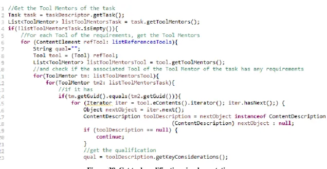
Figure 28. Standard's requirements capture ... 32
Figure 29. Modelled safety process... 32
Figure 30. Standard's requirements mapping ... 33
Figure 31. Activity diagram for fallacy detection method ... 33
Figure 32. Structure of the Argumentation Metamodel [50] ... 35
Figure 33. Activity diagram for the transformation method ... 36
Figure 34. Flowchart of fallacy detection process... 37
Figure 35. Extraction of standard's requirements implementation ... 38
Figure 36. Get selected process element implementation ... 39
Figure 37. Get process elements implementation... 39
Figure 38. Get tool qualifications implementation ... 40
Figure 39. Remove additional information implementation ... 40
Figure 40. List of prepositions and articles ... 41
Figure 41. Fallacy decision implementation ... 41
Figure 42. Method to store the omitted evidence ... 42
Figure 43. Fallacy detection plugin menu ... 42
Figure 44. Method to select the target directory of the report ... 43
Figure 45. Validation completion dialog ... 43
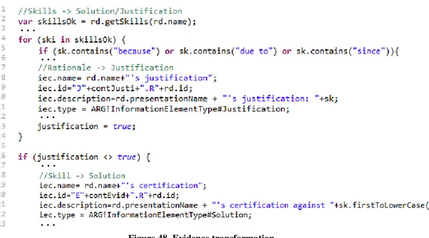
Figure 46. Get skills operation ... 44
Figure 47. Flowchart of transformation plugin ... 45
Figure 48. Evidence transformation ... 46
Figure 49. Get tool qualifications operation ... 47
Figure 50. CapabilityPattern2Claim rule snippet ... 47
Figure 51. Context transformation ... 48
Figure 52. Model repository structure ... 48
Figure 53. Obtaining the models ... 49
Figure 54. Creation of EMF models... 50
Figure 55. Connection to the CDO Repository ... 50
Figure 57. Create diagram method ... 51
Figure 58. Transformation completed dialog ... 51
Figure 59. Open diagram... 52
Figure 60. “Design of software items” requirements ... 54
Figure 61. Modelling ECSS-E-ST-40C standard requirements ... 55
Figure 62. Modelled requirements for AOCS engineer Role ... 55
Figure 63. Modelled requirements for Matlab Tool ... 56
Figure 64. process_lifecycle method elements ... 56
Figure 65. Modelled evidence for AOCS engineer Role ... 57
Figure 66. Modelled evidence for Matlab Tool ... 57
Figure 67. process_lifecycle process elements ... 57
Figure 68. Insufficient evidence dialog ... 58
Figure 69. Staffing Plan report ... 58
Figure 70. Tool Qualification Plan results printed on the console ... 59
Figure 71. Sufficient evidence dialog ... 59
Figure 72. Generated model and diagram ... 60
Figure 73. Representation of the context in the generated argument ... 60
Figure 74. Representation of Work Products and some Guidance elements in the generated argument ... 61
Figure 75. Representation of the AOCS Engineer role with evidences in the generated argument ... 61
Figure A. 1. Open Authoring Perspective ... 68
Figure A. 2. Open Method Library ... 68
Figure A. 3. Fallacy Detection plugin menu ... 69
Figure A. 4. Select directory dialog ... 69
Figure A. 5. Directory dialog ... 69
Figure A. 6. Validation Completion dialog - Open File ... 70
Figure A. 7. Validation Completion dialog - Open Folder ... 70
Figure A. 8. Console results ... 70
Figure A. 9. Model Repository Preferences ... 71
Figure A. 10. Create a new Assurance Project ... 71
Figure A. 11. Transformation plugin menu ... 72
Figure A. 12. Select Assurance Project dialog ... 72
Figure A. 13. Assurance Project selection window ... 72
Figure A. 14. Progress Information message ... 73
Figure A. 15. Transformation completed message ... 73
Figure A. 16. Opening diagram dialog ... 73
Figure A. 17. Transformation results ... 74
Figure A. 18. Drag and drop diagram elements ... 74
List of Tables
Table 1. Key Method Content elements ... 13
Table 2. Key Process elements ... 13
Table 3. Mapping between SACM, GSN and CAE ... 20
Table 4: Taxonomy of Fallacies [21] ... 21
Table 5. Mapping elements ... 34
Table 6. Roles requirements ... 54
Acronyms and Abbreviations
AMASS
Architecture-driven, Multi-concern and Seamless Assurance and Certification of
Cyber-Physical Systems
AOCS
Attitude and Orbit Control Subsystem
CACM
Common Assurance and Certification Metamodel
CAE
Claims-Arguments-Evidence
CDO
Connected Data Objects
CPS
Cyber-Physical Systems
ECSS
European Cooperation for Space Standardization
EMF
Eclipse Modelling Framework
EN
European Norms
EPF
Eclipse Process Framework
ETL
Epsilon Transformation Language
GSN
Goal Structuring Notation
HAZOP
Hazard and Operability
ISO
International Organization for Standardization
M2M
Model-to-Model
MDA
Model-Driven Architecture
MDD
Model-Driven Development
MDE
Model-Driven Engineering
MDSafeCer
Model-Driven Safety Certification
MOF
MetaObject Facility
OMG
Object Management Group
PML
Process Modelling Language
RMC
Rational Method Composer
RUP
Rational Unified Process
SACM
Structured Assurance Case Metamodel
SPEM
Software & System Process Engineering Metamodel
SW
Software
UMA
Unified Method Architecture
UML
Unified Modeling Language
V&V
Verification and Validation
XMI
XML Metadata Interchange
XML
eXtensible Markup Language
1. Introduction
This chapter presents a brief introduction to the work done in this thesis. Section 1.1 explains the main motivation for this work, and the context in which the thesis is developed is explained in Section 1.2. Section 1.3 highlights the main contributions of this thesis. Finally, Section 1.4 gives the idea about the main structure of the thesis.
1.1. Motivation
Standards such as ECSS-E-ST-40C for space [6], ISO 26262 for automotive [3], and EN 50128 for railway [5] provide guidance on the steps and processes that shall be followed during the development of a safety-critical system. Compliance with these normative processes is mandatory for certification of such safety-critical systems. In this context, a safety case, which is a contextualised structured argument, shows that a system is acceptably safe. To accomplish this, the process-based arguments aim to show that the process used to develop the system contributes to its safety, that is, argue about the safety-related decisions and explain how the presented evidence relating and contributing to the safety goals.
However, the creation of process-based arguments is a very costly, time-consuming and laborious task, because inappropriate reasoning in the argumentation through irrelevant premises or insufficient evidence, i.e. a fallacious safety argument, can undermine the credibility of the argument, as well as deteriorate the quality and safety of the system, leading to safety-related failures [14], [20]. Therefore, the avoidance, detection, and removal of fallacies in the argumentation is an essential task to reduce the risk of failures in a safety-critical system. However, since this task depends on the experience and knowledge of the developer, it is also prone to errors.
In order to solve these issues, a model-driven approach can be used to automatically generate process-based arguments from process models [11] and incorporating assistance to avoid these fallacies when engineers are creating safety arguments.
This thesis aims to provide such assistance for safety engineers by developing an automatic method of detecting existing fallacies in the modelled process. Once these fallacies are detected and solved, the safety argumentation is generated automatically from the process model. To reach these goals, this thesis tries to answer the following research questions:
• How do we detect the omission of key evidence fallacy in process-based arguments? • Can we provide process compliance with argumentation?
• Can we increase the quality of safety arguments?
1.2. Context
This thesis is defined in the scope of the ongoing research project AMASS (Architecture-driven, Multi-concern and Seamless Assurance and Certification of Cyber-Physical Systems), which “will create and consolidate the de-facto European-wide open tool platform, ecosystem, and self-sustainable community for assurance and certification of Cyber-Physical Systems (CPS) in the largest industrial vertical markets including automotive, railway, aerospace, space, energy” [42].
The platform proposed by AMASS project integrates several tools for deriving assurance certification elements and is built on top of several Eclipse and PolarSys projects. Since we aim at integrating the solution in this platform, we have to adapt to the existing constraints, so the current process modelling tool (i.e., EPF Composer [46]) and assurance case editor (i.e., OpenCert [43]) are used to implement the functionalities.
1.3. Contribution
This thesis will contribute to enabling the generation of fallacy-free process-based safety argumentations from process models. For this, a Fallacy Detection plugin will be developed within the AMASS platform, which allows safety/process engineers to validate whether the process models contain sufficient information, preventing thereby the occurrence of fallacy (i.e., omission of key evidence) in process-based argumentations. Through this thesis, the following outcomes are provided:
• Study state of the art of safety cases and fallacy detection mechanisms, as well as the automatic generation of safety argumentation.
• The design and implementation of an algorithm to automatically detect fallacies (i.e., omission of key evidence) in model-based safety-processes compliant with the OMG standard for modelling processes SPEM 2.0, moreover an analysis of the metamodels elements involved in it.
• Enhance existing implementation: the activation of process-based arguments generator plugin from the EPF Composer, incorporating the presented –and validated– evidence as solutions or justifications. • An illustration of the applicability of the solution through a case study in the context of the space domain
(i.e., compliant with ECSS-E-ST-40C standard).
In addition, as an early result of this thesis, a scientific article [57], which includes the concept and design of this approach, has been presented and accepted in the 11th International Conference on the Quality of Information and Communications Technology (QUATIC).
1.4. Thesis structure
The rest of the report is structured as follows:
Chapter 2 presentsthe background knowledge needed to understand the rest of the report.
Chapter 3 presents the state of the art of the assurance, validation and generation of safety arguments through an
analysis of the related work.
Chapter 4 presents the problem formulation and analysis, which determines the rest of the work. In addition to
the raised research questions, the goal of this thesis is divided into subproblems, which allows addressing these questions and find a proper solution.
Chapter 5 presents the scientific methodology used in this thesis, which is based on analysing a problem, finding
a solution to the problem, and evaluating the solution.
Chapter 6 presents the solution proposed by this thesis. This solution is composed of two different plugins that
perform the fallacy detection functionality, and the transformation process to automatically generate the safety argumentation from the process model.
Chapter 7 introduces a case study to illustrate the applicability of the proposed solution. The modelled process
represents the planning phase of the AOCS software development process, following Clause 5.5 of the ECSS-E-ST-40C standard.
Chapter 8 presents the conclusions obtained from the results of the thesis, including the limitations found during
2. Background
This chapter explains the needed background concepts to be able to understand the rest of the document. For this, Section 2.1 presents the process models and process modelling language, specifically SPEM 2.0. Section 2.2 describes the basic notions of a safety case, such as text-based notations (Section 2.2.1) and graphic-based notations (Section 2.2.2). Section 2.3 presents the argumentation fallacies, and finally, Section 2.4 presents the main concepts of the model-driven engineering approaches.
2.1. Process and SPEM 2.0-based process modelling
A process can be defined as “a series of actions or steps taken in order to achieve a particular end” [1]. More specifically, in the engineering domain, a process is “a series of interrelated tasks that, together, transform inputs into outputs” [2]. The growing complexity, the large number of people involved in the development of software products, as well as the wide range of information that these development teams need and use, has increased the necessity to follow processes to generate quality products and facilitate the development of them.
However, there are systems whose quality and safety must be thoroughly reviewed, called safety-critical systems. These systems are defined as those whose failure can cause loss of life, damage to property or environment. Due to this, numerous standards in the field of safety-critical systems such as ISO 26262 [3] (automotive), DO-178C [4] (airplane), EN 50128 [5] (railway), or ECSS-E-ST-40C [6] (space), specify the activities and tasks –and their order– that must be carried out during the development phase of a safety-critical system. These safety processes are also known as safety-life cycles, and their fulfilment is needed for certification purposes. In this way, they are used to ensure the quality of the developed systems, and thus, to argue that the developed system is safe.
SPEM (Software & System Process Engineering Metamodel), an Object Management Group’s (OMG) standard is one of the Process Modelling Languages (PMLs) that describes processes based on MOF (MetaObject Facility) [7]. Figure 1 shows the four-level standardised architecture proposed by OMG, where the upper level (M3) is the meta-metamodel MOF, and the immediately lower level (M2) is the metamodel SPEM. The lower layer (M1) represents the process model such as RUP, Scrum or XP. Finally, the lowest level (M0) represents the actual process. Since these concepts are related to MDE (Model-Driven Engineering), they will be further explained in Section 2.4.
M3: MetaObject Facility MOF
M2: Process Metamodel SPEM
M1: Process Model e.g. RUP,
SCRUM, XP
M0: Performing Process Software project
Figure 1. Standardised architecture
Specifically, SPEM is “a process engineering meta-model as well as conceptual framework, which can provide the necessary concepts for modelling, documenting, presenting, managing, interchanging, and enacting development methods and processes” [8]. The first version was introduced in 2002 and was built upon UML 1.4. In 2005 appeared the second version, SPEM 1.1 [9], incorporating minor updates and finally, in 2008, the current version SPEM 2.0 was released, which is compliant with UML 2. This includes significant benefits such as greatly improved modelling techniques, graphic interchange capability, and a more modular organisation [8]. In this way, SPEM 2.0 leverages these functionalities and the ability to work with UML 2 tools, enhancing its process modelling techniques and capabilities.
SPEM is based on the idea that a process can be defined as a collaboration between different entities. In particular, SPEM 2.0, through the Method Content package, allows defining a process through the main elements Task, Role and Work Product, where tasks can be grouped into larger structures such as activities and phases (work definition elements). Figure 2 shows the relationship between these elements, where a Role is responsible for one or more Work Product(s), and one or more Role(s) performs one or more Task(s). These Tasks have one or more Work Product(s) as inputs and outputs.
Figure 2. Relationship between Task, Role and Work Product elements [10]
In addition, Guidance and Tool elements can be used to represent the resources and tools that should be used, respectively. This package defines the “what, who and how” of the work that must be done in a process, while the “when” is represented by the Process package. Figure 3 shows the main elements of both packages. While the Method content package provides the concepts to define static and reusable process elements, that is, independent of any specific process or development project, the Process package places these concepts into the context of a specific life-cycle. The key Method Content elements (left-hand side of the diagram) are further described in Table 1. An example of a safety process modelling with SPEM 2.0 is shown in Figure 4.
Figure 3. SPEM 2.0 Method Framework [8]
On the right-hand side of the diagram are the SPEM 2.0 Process elements. As said before, the Method Content elements can be placed and applied in a specific life-cycle process. When that happens, reference classes to the static Method Content classes are created, referred to as Method Content Use (i.e., Task Use, Role Use, and Work Product Use). These classes referred to their Method Content ones, but can store individual changes with respect to them. In addition to these referred classes, the main Process element is the Activity, which allows defining Breakdown structures and relationships to define a workflow. Table 2 includes a brief description of the main Process elements.
Table 1. Key Method Content elements
Element Icon Description Examples
Task Describes an assignable unit of work. This work has to be performed by one or more Role(s) and has input and output Work Products. A
Task can be defined by different steps.
Define requirements, Define Use Cases, Identify Hazards Role Describes who is responsible for the work. A Role can be an individual
(e.g. project manager) or a set of individuals (e.g. development team). It also defines related skills, competencies, and responsibilities. A Role may be responsible for one or more Work Product(s) and may perform one or more Task(s).
Developer, designer, project manager, system analyst, software engineer
WorkProduct Defines tangible artefacts consumed, produced, or modified by a Task. A Task has Work Products as input and output. A Work Product can be optional or mandatory. The types of work products are: Artifacts, Deliverables, and Outcomes.
Functional
requirements, HAZOP analysis
Tool Describes the capabilities of a tool to perform the work defined in a
Task. It can be defined as useful, recommended or necessary for a Task's completion.
Use Cases tool, HAZOP package
Guidance Describes additional information related to any model element to, for example, define how to perform the work defined in a Task. The specific type of Guidance must be selected. The types of guidance are: Checklists, Concepts, Examples, Guidelines, Estimation Considerations, Practices, Reports, Reusable Assets, Roadmaps, Supporting Materials, Templates, Term Definitions, Tool Mentors, and Whitepapers.
Unified Modelling Language (UML), HAZOP template and guidelines
Table 2. Key Process elements
Element Icon Description
TaskUse Represents a Task in the context of a specific activity. One Task can be represented by many
Task Uses, each with a different set of relationships (with Role Uses and Work Product Uses)
depending on the activity in which is instantiated. In addition, the Task Use element indicates what subset of steps shall be performed at that particular point in the process.
RoleUse Represents a Role in the context of a specific activity. One Role can be represented by many
Role Uses, each with different relationships and responsibilities depending on the specific
activity in which it is involved. WorkProduct
Use
Represents a Work Product in the context of a specific activity. One Work Product can be represented by many Work Product Uses, where each one can include different relationships depending on the specific activity in which it is involved.
Process Describes the structure for particular types of development projects or part of them, by adapting to the specific situation and needs of the project, and assigning the proper method and process elements.
Activity Represents a set of nested Breakdown Elements, that is, any type of Process element that is part of a breakdown structure. This can include other Activity instances such as Phases, Task Uses, etc.
Phase Represents a significant period in a project, which usually ends with a milestone or a set of deliverables. It is a special predefined Activity since its use has a great significance in the definition of breakdown structures. A Phase can be considered as an Activity which is not repeatable.
Delivery Process
Describes a complete approach, i.e., that covers the development life-cycle from beginning to end, for performing a specific project type. It provides a complete life-cycle model with predefined phases and activities, detailed by arranging the referred method content in breakdown structures. In addition, it defines what produces and by who, in the form of Work Product Usage and Team Allocation structures.
Capability Pattern
Also called Process Pattern, describes a reusable cluster of Activities that provide a consistent approach to common structures, such as “use case-based requirements management” or “develop components”. It does not relate to any specific phase of a development life-cycle.
2.2. Safety arguments and modelling
Safety cases are gaining importance in different areas such as automotive, railway, aerospace or nuclear since they are mandatory for certification purposes. Due to the growing number of fields, organisations and people that work with safety-critical systems, different definitions for safety cases can be found. According to the U.K. Ministry of Defence, a safety case is “a structured argument, supported by a body of evidence that provides a compelling, comprehensible and valid case that a system is safe for a given application in a given operating
environment” [12]. This definition, therefore, describes the general structure of a safety case, shown in Figure 5.
The previous figure shows that the role of the safety argument is, therefore, the relationship between the evidence and the objectives. According to Kelly, “a safety case should communicate a clear, comprehensive and defensible argument that a system is acceptably safe to operate in a particular context” [13]. That is, not only substantial supporting evidence is necessary for a safety case to be successful, but it is also essential to explain clearly and convincingly how this evidence relating to the safety objectives. Therefore, both parties are essential since a safety case without evidence is unfounded, and a safety case without argument is unexplained.
A safety argument is therefore the part of a safety case that tries to explain and relate how the presented evidence allows ensuring that the system complies with the safety requirements and objectives demanded by all the stakeholders involved. More formally, a safety argument, like any other argument, is a claim supported by other claims or premises. Damer defines in [14] that “an argument is constituted by two or more explicit and / or implicit claims, one or more of which supports or provides evidence for the truth or merit of another claim, the conclusion.”
Arguments can be classified as deductive or inductive arguments. The former is one in which the premises guarantee the truth of the conclusion, which is a logical consequence of the premises; that is, if the premises are true, then the conclusion must also be true. The latter is the one where the conclusion is taken as true, and the premises provide reasons to support the alleged veracity of the conclusion. However, in this type of arguments the conclusion does not follow any logical consequence with respect to the premises, so the truth of all its premises would not imply the truth of the conclusion. Safety arguments are of this type, i.e., inductive arguments.
Safety arguments can also be classified as product-based or process-based. The first ones are focused on ensuring the quality and safety of the attributes and objectives of the finished product. The second ones are focused on the quality and adequacy of the process followed during the development of the product. However, although these types of argumentation can be represented individually, they can also be related, and an argument can include process and product-based sub-arguments. As stated in the previous section, following a process improves the quality of the element developed, therefore, process-based arguments can ensure that the product-based evidence is trustworthy since it has followed the proper process.
To document safety arguments within a safety case, several approaches exist both textual (e.g., normal prose, structured prose, argument outline, mathematical proof style, LISP style) and graphical (e.g., Goal Structuring Notation, Claims-Arguments-Evidence) [15], which are presented below. Besides, the Object Management Group offers a standardised modelling language for representing safety cases; the Structured Assurance Case Metamodel (SACM) 2.0 [16]. It aims to unify and standardise the graphical notations broadly used for documenting safety cases, namely GSN and CAE.
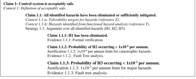
15 Claim 1: Control system is acceptably safe.
Context 1: Definition of acceptably safe.
Claim 1.1: All identified hazards have been eliminated or sufficiently mitigated. Context 1.1-a: Tolerability targets for hazards (reference Z).
Context 1.1-b: Hazards identified from functional hazard analysis (reference Y).
Strategy 1.1: Argument over all identified hazards (H1, H2, H3). Claim 1.1.1: H1 has been eliminated.
Evidence 1.1.1: Formal verification.
Claim 1.1.2: Probability of H2 occurring < 1x10⁻⁶ per annum.
Justification 1.1.2: 1x10⁻⁶ per annum limit for catastrophic hazards. Evidence 1.1.2.: Fault Tree analysis.
Claim 1.1.3: Probability of H3 occurring < 1x10⁻³ per annum.
Justification 1.1.3: 1x10⁻³ per annum limit for major hazards. Evidence 1.1.3: Fault tree analysis.
2.2.1. Text-based notations
➢ Normal proseCommonly used in disciplines such as law or philosophy, safety cases can be written using natural language. Figure 6 shows a fragment of a safety argument written in normal prose.
➢ Structured prose
One of the main problems of the normal prose approach is the lack of structure in the argument, as well as the difficulty to identify the main elements of the argument (e.g., claims and strategies). With the structured prose approach, it is intended to improve these problems with constrained prose to denote these essential parts explicitly. Figure 7 shows an example of a structured prose argument fragment.
➢ Argument outline
This approach allows defining the structure of the argument even more explicitly. To do this, simple phrases are used to define each of the elements with a different type of font (bold - claim, italic - context, etc.), as well as indentation and numbering to highlight the hierarchy of the elements. Figure 8 shows an example of this approach.
The control system is acceptably safe, given a definition of acceptably safe, because all identified hazards have been eliminated or sufficiently mitigated and the software has been developed to the integrity levels appropriate to the hazards involved.
Given both the tolerability targets for hazards (from reference Z), and the list of hazards identified from the functional hazard analysis (from reference Y), we can show that all identified hazards have been identified or sufficiently mitigated by arguing over all three of the identified hazards: H1, H2, and H3.
We know from the formal verification we conducted that H1 has been eliminated.
We know that catastrophic hazard H2 has been sufficiently mitigated because fault tree analysis […]. We know that major hazard H3 has been sufficiently mitigated because fault tree analysis […].
This argument establishes the following claim: the control system is acceptably safe, within the context of a definition of acceptably safe. To establish the top-level claim, two sub-claims are established: (1) all identified hazards have been eliminated or sufficiently mitigated and (2) the software has been developed to the integrity levels appropriate to the hazards involved.
Within the context of the tolerability targets for hazards (from reference Z) and the list of hazards identified from the functional hazard analysis (from reference Y), we follow the strategy of arguing over all three of the identified hazards (H1, H2, and H3) to establish sub-claim 1, yielding three additional claims: H1 has been eliminated; H2 has been sufficiently mitigated; and H3 has been sufficiently mitigated.
The evidence that H1 has been eliminated is formal verification.
The evidence that catastrophic hazard H2 has been sufficiently mitigated is a fault tree analysis […]. The evidence that the major hazard H3 has been sufficiently mitigated is a fault tree analysis […].
Figure 6. Example of Normal Prose argument [16]
Figure 7. Example of Structured Prose argument [16]
➢ Mathematical proof style
The mathematical proof approach allows structuring the argument through claims (defined with the word “Establish”), followed by its context (under the label “Given”), and a series of statements and reasons organised in a table as Figure 9 shows. This type of approach allows making references to established claims later, so it maintains the top-down nature of the argumentation [17].
➢ LISP Style
This approach is based on the LISP programming language. Each element of the argument appears at the beginning of a list, indexed in such a way that it applies to everything that follows within that list. Figure 10 shows an extract of an example of this type of notation.
2.2.2. Graphics-based notations
As mentioned above, besides the already presented text-based notations there are other methods to represent safety arguments, such as graphics-based ones namely GSN and CAE, which are described below.
Establish:
SystemSafe: Control system is acceptably safe. Given:
A. Definition of acceptably safe.
Statements Reasons
1. All identified hazards have been eliminated or sufficiently mitigated
1. HazardsHandled (established below) 2. The software has been developed to the integrity level
appropriate to the hazards identified
2. ProcessAcceptable (established below)
3. Control system is acceptably safe 3. 1, 2
Establish:
HazardsHandled: All identified hazards have been eliminated or sufficiently mitigated. Given:
A. Tolerability targets for hazards (reference Z).
B. Hazards identified from functional hazard analysis (reference Y). By: Arguing over all identified hazards (H1, H2, H3)
Statements Reasons
1. H1 has been eliminated 1. formal verification
2. p(H2) < 1x10⁻⁶ per annum (p.a.) 2. fault tree analysis 3. Upper limit on permitted catastrophic hazard occurrence
is 1x10⁻⁶ p.a.
3. Given (A)
4. H2 has been mitigated 4. 2,3
... ...
(context DefSafe (claim SystemSafe (context FHAHazards (context Targets (claim HazardsHandled (strategy ArgOveHaz (claim H1Elim (evidence H1Evidence)) (claim H2OK (justification CatHaz) (evidence FTA))
Figure 9. Example of Mathematical Proof Style argument [16]
{Context Identifier}
<Context Statement>
➢ Goal Structuring Notation (GSN)
GSN is one of the most commonly used notations to represent safety arguments. It can be defined as “a graphical argument notation which can be used to document explicitly the elements and structure of an argument and the argument’s relationship to evidence” [18]. It is based on the Toulmin’s argumentation theory called “Toulmin Model” and on goal-based approaches to requirements engineering, such as KAOS. The main characteristic of this notation is the organisation of the argument in ‘goal structures’. A goal structure shows how the goals of a system are broken down in turn into different sub-goals until reaching those in which direct evidence is sufficient. Therefore, a goal structure is formed by the different types of elements existing in a safety argument and the relationship between them. The symbols and concrete syntax to describe these elements are described below.
Core elements
The main elements in GSN, also known as nodes, are the following: • Goal
As stated in Section 2.2, an argument is composed of a series of premises that supports the truth of the main premise (e.g., the safety of a system). Each of these premises or claims of a system –or of a property of the system– are represented in GSN as goals. This element is rendered as a rectangle. An example of a goal can be seen in Figure 11.
• Strategy
When a goal is broken-down into sub-goals, a strategy is used to explain what reasoning has been followed to arrive at that decomposition, that is, how or why a goal is decomposed into sub-goals. Therefore, it is used to provide additional description or explanation of the reasoning about a connection or relationship between one or more Goals (premises) to another Goal (conclusion). The symbol used is the parallelogram, as can be seen in Figure 12.
• Context
The context element defines the boundaries in which a goal or strategy should be interpreted. This element thus allows providing additional information to support the core reasoning of the argument. It is represented by a rectangle with rounded corners as shown in Figure 13.
• Solution
As stated before, a ‘goal structure’ ends when a goal can be solved by direct evidence instead of by decomposition into sub-goals. Direct evidence is represented in GSN as solutions and rendered as a circle as shown in Figure 14. A solution is, therefore, a reference to an evidence item, and it usually is an analysis result (e.g., FMECA, HAZOP, FTA), a verification tests result, a certification, etc.
{Goal Identifier}
<Goal Statement>
{Strategy Identifier}
<Strategy Statement>
Figure 11. Example of Goal element
Figure 12. Example of Strategy element
• Justification
This element provides additional reasoning to support another element, for example, the choice of a specific strategy. It is also used to provide additional description or rationales about a premise, which is intended not supported by evidence. A Justification element is rendered as an oval with a letter ‘J’ at the bottom-right as shown in Figure 15.
• Assumption
This element presents an intentionally unfounded statement, which must be taken as true without providing further explanations. It is rendered as an oval with a letter ‘A’ at the bottom-right as shown in Figure 16.
• Undeveloped entity
A hollow diamond at the centre-bottom of a goal indicates that the element has been intentionally left undeveloped in the argument. Figure 17 shows an example of this element.
Relationships
The elements presented above are combined to represent goal structures, creating thus the safety argument. This is done in GSN by linking them, based on their relationship, using one of the following types of connectors:
• SupportedBy
Rendered as a line with solid arrowhead, it is used both for inferential relationships; i.e., those that show the relationships between different goals, and for evidential relationships; i.e., those that show the relationship between different goals, and for evidential relationships; i.e., those that show the relationship between a goal and its supporting evidence. Figure 18 shows a representation of this relationship.
{Solution Identifier} <Solution Statement> {Justification Identifier} <Justification Statement> J {Assumption Identifier} <Assumption Statement> A {Undeveloped Goal Identifier} <Goal Statement>
Figure 15. Example of Justification element
Figure 16. Example of Assumption element template
Figure 17. Example of Undeveloped Goal Figure 14. Example of Solution element
The permitted supportedBy connections are: goal-to-goal, goal-to-strategy, goal-to-solution, strategy-to-goal.
• InContextOf
Rendered as a line with hollow arrowhead, it is used to contextual relationships. Figure 19 shows the representation used for this kind of relationship.
The permitted inContextOf connections are: goal-to-context, goal-to-assumption, goal-to-justification, strategy-to-context, strategy-to-assumption, and strategy-to-justification.
Syntax
As Figures 11 to 17 show, all the core GSN elements are represented by a graphical symbol and a textual statement. In addition, an optional identifier can be added to each element, represented here in brackets. If identifiers are included, they must uniquely identify each element. Regarding the textual content of the nodes, there is no formal syntax to describe it. However, informally the goal and justification elements shall be a noun phrase plus a verb phrase sentence, while the solution elements shall be a noun-phrase.
➢ Claim-Argument-Evidence (CAE)
Besides GSN, there is another graphical as well as textual notation called Claim-Argument-Evidence (CAE) [19]. It is based on the same principle as GSN, but with a different representation of the main elements. These elements are the followings:
• Claim: rendered as a blue ellipse, it is a statement within an argument that can be true or false. It is supported by sub-claims, arguments, or evidence, and can also be defined by additional information as context.
• Argument: rendered as a green rounded rectangle, it is an optional element used to provide a description of the approach of the argument.
• Evidence: rendered as a magenta rectangle, it is a reference to the supporting evidence of the claim. In addition to these key elements, the relationship between them is modelled through a coloured arrow, depending on the colour of the source element, which in turn can represent three types of relationships, namely isEvidenceFor, isAsubclaimOf, and supports. The difference regarding GSN is that the relationship is bottom-up instead of top-down. That is, instead of saying that A is supported by B, it is said that B supports A. Figure 20 shows an example of these elements and relationships to form a CAE argument.
Figure 20. CAE example [19] Figure 18. SupportedBy relationship
On the other hand, as stated before, the OMG’s standardised modelling language SACM 2.0 aims to unify these graphical notations. Table 3 shows the mapping between SACM elements with GSN and CAE, according to the references provided in Annex A: Mappings from Existing Industrial Notations for Assurance Cases by the OMG’s documentation of SACM [16].
Table 3. Mapping between SACM, GSN and CAE
GSN Element CAE Element SACM Element
Node Elements:
Goal (Rectangle) Claim (Blue ellipse) Claim
Strategy
(Parallelogram) Argument (Green rounded box) ArgumentReasoning
Solution (Circle) Evidence (Magenta rectangle) InformationElement linked with AssertedEvidence Context (Rounded
rectangle) Side-warrant (Red ellipse) InformationElement linked with AssertedContext Link Elements:
supportedBy (Filled arrow)
isSubclaimOf (Blue arrow) supports (Green arrow) isEvidenceFor (Magenta arrow)
AssertedInference from Claim to another Claim AssertedInference from Claim to ArgumentReasoning AssertedEvidence
inContextOf (Empty
arrow) Green arrow AssertedContext
2.3. Argumentation fallacies
As stated in the previous section, the safety argument is an essential part of a safety case and mandatory in many fields for certification purposes. Hence, it is a crucial aspect of those safety-critical systems, where the quality of the presented evidence is as important as the fact that the evidence is actually related to safety requirements. This is where the role of the safety argument acts, so that a correct and quality safety argument is essential for a safe system. According to numerous studies ([14], [20], [21], [30], [31], [36]), faulty reasoning in the safety argument, i.e., a fallacious safety argument, can deteriorate the quality of the system, leading to safety-related failures.
A flawed or fallacious safety argument is the one where the premises that comprise it do not provide enough evidence to guarantee the truth of the conclusion, and thus, is an invalid one.
Damer in [14] argues that there are five criteria of a good argument: Structural, Relevance, Acceptability, Sufficiency, and Rebuttal. The structural principle concerns the soundness of its structure, that is, there are no premises that contradict each other or that implicitly assume the truth. The relevance principle concerns that the premises must be related and be relevant to the truth of the claim they support. The acceptability principle refers to an argument that provides reasons that a mature and rational person should accept with the help of specific guidelines. The guidelines regarding what should be accepted are called “standards of acceptability”, and those regarding what should not be accepted are called “conditions of unacceptability”. For example, the former includes as a standard for accepting a premise “A claim that is a matter of undisputed common knowledge”, and the latter includes as a condition for not accepting a premise “A claim that is self-contradictory or linguistically confusing”, among others. The sufficiency principle concerns the amount and weight of the premises that support the conclusion. That is, an argument must have a sufficient number of proper evidence to support the truth of the claim. Finally, the rebuttal principle, which states that an argument should include a rebuttal to the possible anticipated criticisms that may be brought against it. Based on this, a fallacy can be defined as the reasoning in an argument that violates any of the above criteria.
Usually, disciplines such as logic and philosophy classify the fallacies either as formal (also called deductive or logical); which can be defined in a standard logic system, or as informal (also called inductive); which do not consider the logical structure of the argument, but the content of the argument. These last ones are the most difficult to detect because, in many cases, the natural language of the arguments allows to dissuade or deceive the reader as well as to camouflage the intentionality of the fallacies. In addition, an argument may not contain any formal fallacy and still not be valid, because although the logic of the structure is valid, the reasoning or the evidence presented in it may be erroneous (informal fallacies). A safety argument can contain both types of fallacies, so a more accurate classification is necessary.
For this, numerous types of fallacies and classifications exist, such as the one proposed by Damer in [14, p. 54], with 12 categories and more than 60 types. However, after an analysis carried out in both general arguments and real safety arguments, Greenwell et al. created a Safety Argument Fallacy Taxonomy [21], composed of common fallacies that can appear in safety arguments. Table 4 shows the complete taxonomy.
Table 4: Taxonomy of Fallacies [21]
A safety fallacy is, therefore, a mistake or a flaw in the reasoning of an argument that may go unnoticed or not seem a failure. However, avoiding fallacies during the development phase and detecting them during the revision phase is crucial to avoid future failures in the safety of the system. A description of all categories and fallacies of the taxonomy can be found in [22]. For the purpose of this thesis, only the omission of key evidence fallacy, which is defined below, is focused.
➢ Omission of Key Evidence fallacy
As mentioned in the previous section, there are five criteria to make a good argument, among which is the sufficiency one. To meet this criterion, sufficient and not biased evidence need to be provided, as well as the expected evidence, in number and type, for its particular claims.
Therefore, an omission of key evidence fallacy occurs when an argument fails to provide one or more of the expected evidence to justify or support the claim.
2.4. Model-driven engineering
Model-Driven Engineering (MDE) is considered as a promising paradigm in software engineering based on the principle that everything is a model [23]. More specifically, this suggests that to develop a software system, first its model must be developed theoretically, and then transformed it by model transformations into a real entity, that is, an executable code. MDE not only focuses on the model transformations but also the entire process followed to develop software, recognising other important factors such as communication between stakeholders and improving the speed of the response to changes in a system [24]. MDE refers in turn to different development approaches based on modelling software such as Model-Driven Architecture (MDA) and Model-Driven Development (MDD), which are described below. Figure 21 shows a diagram that relates these three model-driven concepts. Circular Reasoning Circular Argument Circular Definition Diversionary Arguments Irrelevant Premise Verbose Argument Fallacious Appeals
Appeal to Common Practice
Appeal to Improper/Anonymous Authority Appeal to Money Appeal to Novelty Association Fallacy Genetic Fallacy Mathematical Fallacies Faith in Probability Gambler’s Fallacy Insufficient Sample Size Pseudo-Precision Unrepresentative Sample Unsupported Assertions
Arguing from Ignorance Unjustified Comparison Unjustified Distinction
Anecdotal Arguments
Correlation Implies Causation Damning the Alternatives Destroying the Exception Destroying the Rule False Dichotomy Omission of Key Evidence
Omission of Key Evidence Fallacious Composition Fallacious Division
Ignoring Available Counter-Evidence Oversimplification Linguistic Fallacies Ambiguity Equivocation Suppressed Quantification Vacuous Explanation Vagueness
Figure 21. Relationship between MDE, MDA, and MDE [23]
To understand this, it is necessary to define what is a model. A model is “a representation of a real-world process, device, or concept” [25], that is, an abstraction of specific aspects and relevant details of the structure or behaviour of a real-world system. In order for a model to be processed by tools and correctly interpreted by all stakeholders, it must be formally defined. For that, the structure, terms, notations, syntax, semantics, and integrity rules of the information in the model (i.e., the modelling language) must be well defined and consistently represented [26]. A metamodel, therefore, defines the abstract syntax of a modelling language.
In the same way, a meta-metamodel is defined above it and specifies the underlying layer (i.e., a metamodel). Due to its “infinite” nature and in order to standardise this, the OMG defined the known as “four layered metamodel architecture”, that limit the metamodeling process to four levels; M3 or meta-metamodel level, M2 or metamodel level, M1 or model level, and M0, which represents the system. Although this was retracted in later releases (where the rigidity of this restriction is eliminated, being able to use from a minimum of two layers to those that the user defines), the four-layered architecture was widely accepted and adopted.
In fact, this general metamodel architecture is the one used in the MOF specification and is known as MOF Metadata Architecture, where the upper layer M3 is always MOF. The primary objective of this is that all modelling languages are based on MOF as their meta-metamodel. This is the case for the SPEM 2.0-based process modelling, specified in Figure 1. In addition, Figure 22 shows an example of the general four-layers architecture.
Figure 22. Four-layered Metamodel Architecture adapted from [27]
2.4.1. Model-driven architecture
Model-Driven Architecture (MDA) was proposed by OMG in 2001 and encompasses a set of standards with the aim of separating business and application logic from the underlying platform technology, thus allowing technological changes not to affect the results of modelling. For this, “the MDA set of standards includes the representation and exchange of models in a variety of modelling languages, the transformation of models, the production of stakeholder documentation, and the execution of models” [26].
To achieve this separation between the specifications of the system and the platform on which it will be developed, MDA proposes three types of model (namely CIM, PIM, and PSM), which are described below.
• Computational Independent Model (CIM) represents the operation of the system as well as the interaction with other systems and with external users. It can also include the requirements, system objectives, laws of a domain, stakeholder needs, etc. The typical way to represent CIM is by Use Case diagrams.
• Platform Independent Model (PIM) captures the behaviour of the system, that is, its functionality and structure regardless of the technology and platform to be used. This model is represented by UML and other OMG modelling standards.
• Platform Specific Model (PSM) is a model that is defined in terms of a specific platform. PSM complements the PIM model, adding specific technological details of the platform on which it is going to be carried out.
Therefore, the main objective of MDA is to automatically convert a PIM (based on the kernel technologies and focused on the concepts and business requirements) into different PSMs (corresponding with different middleware platforms) [23]. These kernel technologies and middleware platforms can be seen in Figure 23 in the inner part and the middle ring respectively. Also, the outer ring describes the public services provided by MDA, and in the arrows, the high-level domains, that is, the context and purpose of the model.
Figure 23. Overview of MDA [26]
2.4.2. Model-driven development
Another concept related to the model-centric approaches is the Model-Driven Development (MDD). This one is again focused on the model as the primary form of software development, allowing to manage the complexity of it and thereby improve productivity.
The main difference between this and the previous ones is that in MDD the use of OMG standards is not restricted as in MDA, being thus more flexible and allowing to use the one that best suits the user. Besides, it focuses only on the transformation from abstract to concrete, that is, from models to code, without including reverse engineering as, for example, in MDE [24].
2.4.3. Model transformations
An essential element for all the concepts described above is the model transformation. According to Kleppe et al. [28], a model transformation is defined as follow:
“A transformation is the automatic generation of a target model from a source model, according to a transformation definition. A transformation definition is a set of transformation rules that together describe how a model in the source language can be transformed into a model in the target language. A transformation rule is a description of how one or more constructs in the source language can be transformed into one or more constructs in the target language.”
Therefore, a model transformation can be defined as a set of rules that define how to automatically map a model in a source language into another model in a target language. This allows converting one type of model into another, a model into concrete implementation of code, or defining a model from specific source code, through the following types of transformations:
• Model-to-model (M2M) transformation converts a source model (e.g., a PIM) into a target model (for example another PIM or a PSM). Both source and target models can have the same or different metamodel. To this end, there are numerous model-transformation languages, including ATLAS Transformation Language (ATL), Query/View/Transformations (QVT), Janus Transformation Language (JTL), or Epsilon Transformation Language (ETL), which will be used in this thesis. • Model-to-text (M2T) transformation, also known as model-to-code (M2C) or code generation,
converts an abstract model into a specific entity of code. Some of the technologies and frameworks that provide M2T transformation are Acceleo, Xtend, Xpand, JET or MOFScript, among others.
• Text-to-model (T2M) transformations allow reverse engineering, that is, to extract a high-level model from a specific code.
3. Related work
In order to make the process of assurance and review of safety arguments more trustworthy, and mainly, less costly and time-consuming, many approaches have been proposed to try to detect and avoid fallacies in such safety arguments. Kelly presents in [29] a systematic review process based on four steps, which are: (1) Argument comprehension, (2) Well-formedness checks, (3) Expressive sufficiency checks; and (4) Argument criticism and defeat; where the elements of rebuttal and undercutting are included. In [30], Yuang and Kelly propose an argument schemes approach to: (i) avoid fallacies by constructing arguments through a series of ten argument schemas and templates; and (ii) detect fallacies once the argument is developed through a set of critical questions (CQs), which reveal weaknesses or flaws in the argument if they cannot be adequately answered. In another paper [31], Yuang et al. propose a Safety Argument Review Model (SARM) and a dialogue-based tool for safety arguments review (DiaSAR). This tool, through a graphic interface, allows the “argument proposer” (i.e., who creates and defends the argument) to connect with the “reviewer” (i.e., who questions and rebuts the argument, as well as proposes counter-arguments). However, the quality of the reviewed arguments depends on the knowledge and expertise of the reviewers, and therefore its correctness cannot be guaranteed.
Although these kinds of tools and techniques make the process easier, both for system engineers to develop the argument and for the other stakeholders to review and evaluate it, they are informal logic argument schemes. In a closer step to automation, in [32], [33], [34], and [35], different approaches to formalising the safety arguments are proposed. In [32], Groza and Marc propose an ontology that formalises GSN, translating thereby the arguments represented in GSN into description logic, specifically in ALC (Attribute Concept Language with Complements). In addition, this approach is implemented as a tool for possible automation. On the other hand, Rushby proposes in [33] the representation of arguments in a classical formal notation, in particular, in the higher-order logic one (HOL). He states that the elements of the argument can be described in any modelling formalism able to use “Satisfiability Modulo Theories (STM) solvers” (e.g., PSV), supporting thus strong and automated deduction methods such as theorem proving and model checking. In another paper [34], Rushby proposes an improvement of this approach by adding “defeater” predicates to the premises of the formalised cases. These “defeaters” –also known as “undercutting”, “undermining” and “rebutting”– are initially set to false, and the reviewer can activate it to see the consequences, as well as add additional premises and restrictions. Finally, Brunel and Cazin [35] proposed: (a) a framework to represent an argument in ForSALE language (Formal Safety Argumentation Language and Environment), and (b) a formal semantics that allows automatic validation of the argumentation, formalising claims and sub-claims in Linear Temporal Logic (LTL). These approaches try to automate the verification of the argument by using formal logic.
Similarly, a predicate logic-based approach is presented in [36]. This approach differs from the previous ones since it is based on the formal representation of the sentences contained inside the GSN nodes, not the entire argument. For that, they propose an ontology that contains a set of constant, function, and predicate symbols, which create the expressions of GSN nodes. The vocabulary ontology was derived from a domain analysis of existing safety cases, based on the frequency of relevant keywords that appears in them, so the search function only works if the words used in the argument are stored in the database. The fallacies consider in this approach do not include the omission of key evidence.
Despite this, Sokolsky et al. claim in [37] that “complete formalization of the claims in an assurance case is unlikely to be achieved”. Graydon also claims in [38] that a complete formalisation would limit the reading audience to those who can read formal logic and would make the argument less comprehensible and read-friendly. Besides, after a systematic survey and analysis of the literature, he states that there is no evidence of such formalisation helps to avoid or detect the informal fallacies, for which a human review is needed.
Greenwell and Knight [20] present a systematic approach called Pandora for analysing safety-related digital system failures based on the concept of safety cases. They state that such digital failures usually indicate the presence of fallacies in the related safety arguments so, the approach derives evidence from a failure to discover safety fallacies, and then propose recommendations for addressing the discovered fallacies, generating a revised safety argument. However, this approach begins with the pre-failure safety case, so it depends on the completeness of a safety case and cannot be used to prevent the fallacies.
Ayoub et al. present in [39] a systematic approach to construct confidence arguments, that is, those whose overall confidence is considered acceptable, and to identify and manage the weaknesses associated with the software safety arguments. They propose a common characteristics map, that is, a structured collection of the common concerns about the trustworthiness (e.g., tool qualification for tool-derived evidence), to provide guidelines for generating positive confidence arguments. In another paper [40], they present a structured approach for assessing the overall level of sufficiency of safety arguments. For that, they use the concepts of belief
combination and basic probability assignment to calculate the overall sufficiency –or insufficiency– of the safety arguments, based on a measure of sufficiency –and insufficiency– for each node.
Denney and Pai [41] have developed a toolset for assurance case automation, named AdvoCATE. This tool supports the automatic creation of assurance arguments, the integration of formal methods, and an automatic pattern instantiation (either interactively or by the data extracted from tools of hazards and safety requirements analysis), among others. In addition, it supports verification of the arguments, specifically structural properties (e.g., no cyclic links, internal completeness), that is, it checks the soundness and well-formedness of the argument, but not its contents.
However, most of these papers either focus on the verification of the overall structure of the argument (structural principle), or are based on the expert opinion and manual generation and review. In contrast, our approach provides the detection of the omission of key evidence fallacy (sufficiency principle) in process models, and the automatic generation of fallacy-free process-based safety arguments from these models, without the need for a complete safety case, allowing thus the prevention of committing such fallacies.
![Figure 3. SPEM 2.0 Method Framework [8]](https://thumb-eu.123doks.com/thumbv2/5dokorg/4734669.125370/12.892.117.686.122.323/figure-spem-method-framework.webp)
![Figure 9. Example of Mathematical Proof Style argument [16]](https://thumb-eu.123doks.com/thumbv2/5dokorg/4734669.125370/16.892.108.786.229.719/figure-example-mathematical-proof-style-argument.webp)
![Figure 21. Relationship between MDE, MDA, and MDE [23]](https://thumb-eu.123doks.com/thumbv2/5dokorg/4734669.125370/22.892.324.585.582.930/figure-relationship-mde-mda-mde.webp)