Electric Road Systems
Impact on Road Construction,
Maintenance and Operations
TI VTI rapport 1052APublished 2020
vti.se/publications Lina Nordin
Terence McGarvey Ehsan Gahfoori
VTI rapport 1052A
Electric Road Systems
Impact on Road Construction,
Maintenance and Operations
Lina Nordin
Terence McGarvey
Ehsan Ghafoori
Author: Lina Nordin (VTI), Terence McGarvey (VTI), Ehsan Ghafoori (VTI) Reg. No., VTI: 2016/0505-8.1
Abstract
The Swedish Transport Administration is investigating different aspects that can help contribute to the transition towards fossil free transportation. Electric Road Systems (ERS) is one of many interesting concepts that are currently being considered. The aim in this report was to examine the various electrified road concepts through literature reviews, discussions with experts and electric road developers, and visits to the electrified road demonstration projects in Sweden. Analyses were made with regards to how the construction, maintenance, and operations could be affected by the installation of an ERS. Consideration was also given to the impact on road sustainability from other types of installations currently found in the road structure, such as tramways or electric wiring. Focus was directed on installation procedures and the contracts that regulate current road maintenance and operations.
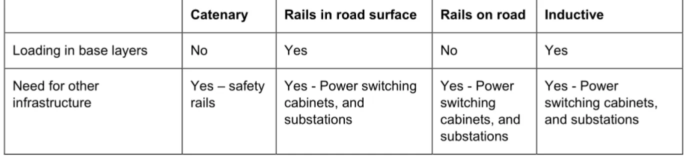
There are large differences between the various ERS concepts. The three main concepts investigated were electric transfer by overhead catenary cables, conductive transfer from a rail on or in the road structure, and the inductive technology which is completely embedded within the road structure. The various concepts all have advantages and disadvantages. For example, the catenary concept will not affect the road surface, whereas the rail and inductive technologies will affect the road structure during the installation procedure and the roads service life. However, the catenary concept will influence maintenance operations by complicating verge maintenance and snow ploughing activities. The embedded inductive technology will probably not affect winter operations; however, the rail concepts will affect winter operations by the need for different types of snow ploughing activities.
Title: Electric Road Systems. Impact on Road Construction, Maintenance
and Operations
Author: Lina Nordin (VTI, http://orcid.org/0000-0001-9313-6238)
Terence McGarvey (VTI, http://orcid.org/0000-0002-6198-0888) Ehsan Ghafoori (VTI, http://orcid.org/0000-0002-5526-5896)
Publisher: Swedish National Road and Transport Research Institute (VTI)
www.vti.se
Publication No.: VTI rapport 1052A
Published: 2020
Reg. No., VTI: 2016/0505-8.1
ISSN: 0347–6030
Project: FFI Research and Innovation Platform for Electrified Roads
Commissioned by: FFI Vinnova and Swedish Transport Administration
Keywords: Electrified roads, ERS, Electric Road Systems, dynamic charging,
conductive energy transfer, inductive energy transfer, catenary transfer, electrified rails, embedded ERS, road maintenance and operations, road construction, inductive ERS, conductive ERS
Language: English
Referat
Trafikverket undersöker olika sätt att minska utsläpp från vägtrafiken samt att använda förnyelsebar energi inom transportsektorn för att nå målet om fossilfria vägtransporter till år 2045. Ett av dessa sätt är de så kallade elvägarna. Syftet med arbetet som redovisas i den här rapporten var att bedöma hur stor påverkan olika aspekter av införandet av elväg kan ha på den vanliga driften och underhållet av vägar. De olika koncepten av elväg analyserades genom litteratursök, samtal med experter och tillverkare av elväg samt besök på olika demonstrationssträckor för elvägar. Därefter har analyser gjorts gällande liknande koncept och deras påverkan på vägkonstruktion, drift och underhåll samt vilka kopplingar som kan göras gällande hur liknande aspekter skulle påverka vägarna, exempelvis andra typer av installationer i vägen, så som spårväg, elledningar m.m. Fokus har varit på
installationsprocesser, och de baskontrakt som drift och underhåll av väg bygger på i nuläget. Det finns stora skillnader mellan koncepten och de tre huvudkoncept som undersökts är konduktiv överföring via luftledningar, konduktiv överföring via skena i eller på vägen och induktiv överföring via spolar som grävts ner under vägytan. Alla koncept har för- och nackdelar där luftledningarna inte gör stor påverkar på själva vägbanan, medan den skenteknik som grävs ner i vägen och den induktiva tekniken påverkar vägen både vid installation och potentiellt även senare under vägens livslängd via belastning från trafik som gör att inbyggda koncept kan ge belastningsskador i ett tidigare skede än normalt. Luftledningar påverkar istället driften av vägen mer eftersom det krävs skyddsräcken vilket försvårar och försenar både snöplogning och slåtter. Den induktiva tekniken är nedgrävd och därför kommer troligtvis inte vinterdriften att påverkas nämnvärt till skillnad från de skenlösningar som finns nedgrävda eller som läggs på vägen där saltning och framförallt plogning kan komma att påverkas genom att ny typ av plog kommer att behövas för att inte skada skenan och för att kunna rensa djupa skenor från snö.
Titel: Elvägar. Effekter med avseende på konstruktion, drift och underhåll Författare: Lina Nordin (VTI, http://orcid.org/0000-0001-9313-6238)
Terence McGarvey (VTI, http://orcid.org/0000-0002-6198-0888) Ehsan Ghafoori (VTI, http://orcid.org/0000-0002-5526-5896) Utgivare: VTI, Statens väg- och transportforskningsinstitut
www.vti.se Serie och nr: VTI rapport 1052A Utgivningsår: 2020
VTI:s diarienr: 2016/0505-8.1
ISSN: 0347–6030
Projektnamn: FFI FOI Plattform för elvägar Uppdragsgivare: FFI-Vinnova och Trafikverket
Nyckelord: Elvägar, dynamisk laddning, konduktiv energiöverföring, luftledningar, elskenor, induktiv energiöverföring, drift och underhåll, vägkonstruktion, inbäddade elvägstekniker
Preface
This report is the result of work package three, within the Research and Innovation Platform for Electric Roads. The platform was financed by FFI / Vinnova and the Swedish Transport
Administration and was divided into several different work packages. Work package three was regarding which kinds of impact electrified roads could have on road construction, operations, and maintenance.
Three different concepts of electric roads where analyzed, where the conductive technologies transmit energy via overhead lines or rails in the road and where the inductive technology would transmit energy inductively via copper coils buried in the road. The purpose of the workpackage was to analyze and elucidate the effects that an electric road could have on existing road operation and maintenance and to compare the different concepts to try to understand how different aspects can have a far-reaching impact on the operation and sustainability of the roads. Lina Nordin has been the work package manager and has compiled most of the report in collaboration with Terence McGarvey and Ehsan Ghafoori. Arrangements and discussions about the work have been done in collaboration with Fredrik Hellman at VTI. The work has included literature reviews as well as discussions and field visits to the first two demonstration projects for electric roads in Sweden, the catenary conductive electric road on E16 and the conductive rail project close to Arlanda. Discussions have also been held within the platform for electric roads, containing a vast collective knowledge of electric roads, as well as on reference group meetings. Operational aspects regarding roads have been regularly discussed with Dan Eriksson at the Swedish Transport Administration. Dan Zethraeus on Elonroad, Jan
Nylander, project manager for the demonstration project at E16 and Håkan Sundelin, project manager for the demonstration project at Gotland, have contributed with valuable comments on the work and the report. Leif Sjögren at VTI has contributed with knowledge regarding road surface measurements. We especially want to thank Stefan Hörnfeldt at NCC who, with his experience of installation and operation of both the Arlanda project and the planning and installation of the demonstration project for inductive technology at Gotland, reviewed the report and contributed with valuable comments and Krister Palo at the Swedish Transport Administration who also reviewed the report and submitted valuable comments and input to the report.
Göteborg, June 2020 Lina Nordin
Arbetspaketsledare Konstruktion, drift och underhåll
Arne Nåbo
Quality review
An external peer review was conducted on 11 December 2019 by Stefan Hörnfeldt, NCC and on 9 March 2020 by Krister Palo, Trafikverket. Lina Nordin has made adjustments to the final report. Research director Leif Sjögren has thereafter reviewed and approved the report for publication on 9 June 2020. The conclusions and recommendations expressed are the authors’ and do not necessarily reflect VTI’s opinion as an authority.
Kvalitetsgranskning
Extern peer review har genomförts den 11 december 2019 av Stefan Hörnfeldt, NCC och 9 mars 2020 av Krister Palo, Trafikverket. Lina Nordin har genomfört justeringar av slutligt rapportmanus.
Forskningschef Leif Sjögren har därefter granskat och godkänt publikationen för publicering 9 juni 2020. De slutsatser och rekommendationer som uttrycks är författarnas egna och speglar inte nödvändigtvis myndigheten VTI:s uppfattning.
List of Content
Summary ...9
Sammanfattning ...11
1. Introduction ...13
2. ERS - Effect on road construction ...14
2.1. Road construction challenges - Catenary ...14
2.2. Road construction challenges – Conductive rail technology ...15
2.2.1. The In-road rail concept – Elways ...16
2.2.2. Evolution Road – On-road conductive rail technology ...17
2.3. Road construction challenges – Inductive technology ...18
2.3.1. Trench-based construction ...18
2.3.2. Micro-trench-based construction ...20
2.3.3. Full lane-width construction ...20
2.4. Impact on Road Construction from Embedded ERS technologies ...21
2.4.1. Pavement joints ...21
2.4.2. Differences in thermal characteristics ...21
2.4.3. Material change within the pavement structure ...22
2.4.4. Geometry ...23
2.4.5. Long term effects from loading ...23
2.5. Potential risks and suggested improvements ...23
2.5.1. Reinstatement improvements ...23
2.5.2. Water Ingress and Drainage ...25
3. Maintenance and operations ...26
3.1. Electricity issues – supply, safety, electric work regulations, installations ...26
3.2. Pavement structure reinstatements ...27
3.3. Comfort Levels ...28
3.4. Wear and tear ...29
3.4.1. Catenary ...29
3.4.2. Conductive rail ...30
3.4.3. Inductive technologies ...30
3.5. Increased maintenance operations due to ERS ...31
3.5.1. Catenary ...31
3.5.2. Conductive rail ...31
3.5.3. Inductive ...32
3.6. Winter Maintenance ...32
3.6.1. Catenary technology ...32
3.6.2. Conductive rail technology ...33
3.6.3. On-road conductive rail technology ...33
3.6.4. In-road inductive technology ...34
4. Climate change impacts ...35
5. Discussion and Conclusion ...36
Summary
Electric Road Systems. Impact on Road Construction, Maintenance and Operations
by Lina Nordin (VTI), Terence McGarvey (VTI) and Ehsan Gahfoori (VTI)
The transport sector is a large contributor of greenhouse gas emissions. Approximately 36% of all CO2 emissions in Sweden comes from road transport, and about 89% of all freight in Sweden is
transported by heavy goods vehicles. The Swedish Transport Administration (STA) is investigating different aspects that can help contribute to the transition towards fossil free transportation. Electric Road Systems (ERS) is one of many interesting concepts that are currently being considered
ERS is basically a concept that provides the possibility for electric vehicles to charge while driving. In Sweden three different concepts are currently being considered: conductive catenary, conductive rail in the road, and embedded inductive.
Research compilations have been made within the FFI/Vinnova and STA funded Research and Innovation Platform for Electrified Roads to analyse the effects that the introduction of electric roads can have on existing road infrastructure and its maintenance and operations.
A challenge with the overhead catenary concept is the large amount of materials required. Large masts need to be installed in the road verge and they may have an impact on the road structure if positioned too close to the road or in erosion prone soils. Overhead cables could in turn create hazardous
conditions during winter conditions as snow and ice could build up and fall down on traffic. Overhead cables may also obstruct maintenance or operation activities that include the use of lifting arms during roadside grass cutting or emptying waste at resting areas. Masts constructed within the road-side safety zone will require safety barriers to protect drivers in case of an accident. Safety barriers will impact the maintenance of the roads by complicating snow removal and grass cutting operations. Grass cutting for instance could take twice as long to complete if masts are present in the road-side area.
Conductive rail and embedded inductive technologies will impact the road construction in different ways than the overhead catenary concept. The systems are constructed within the road structure and electrical wiring as well as drainage is needed at longitudinal intervals. This will require transverse utility cuts that will disrupt the homogenous nature of the road structure and cause uncomfortable driving conditions. In addition, regulations regarding electrical cables in the road area prohibit the installation of cables that will damage the road construction. This will be a challenge for all types of embedded ERS technology. It will be crucial to investigate how to provide power supply transversely from the roadside area to the ERS without causing damage to the road structure and uncomfortable driving conditions. Further impacts or risks with the rail concept are the need for new maintenance operations such as joint sealing, clearing debris from the rail, and snow clearing with special equipment.
It has been shown from Finite Element Model analyses that loading on top of embedded inductive technologies could cause deformation and cracking, and this could in turn lead to water ingress. However, such model analyses were based on inductive technologies with a concrete casing. The new inductive technology that will be tested on Gotland encapsulates copper coils in flexible rubber. Responsibility requirements for an ERS roads need to be investigated further. It may be necessary to have contractors that are responsible for the maintenance of both the ERS and the road. Both parts need to work well together if ERS roads are to become safe and sustainable. During cable installation procedures, operators need, furthermore, to follow the rules and regulations that specify where and how to install electrical components within the road structure.
Sammanfattning
Elvägar. Effekter med avseende på konstruktion, drift och underhåll
av Lina Nordin (VTI), Terence McGarvey (VTI) och Ehsan Gahfoori (VTI)
Transportsektorn bidrar idag till en stor del av Sveriges koldioxidutsläpp, där ca 36 % kommer från vägtransporter, samtidigt som ca 89 % av allt gods transporteras med lastbil. Som ett led i att nå målet om fossilfria vägtransporter till år 2045 utreder Trafikverket olika sätt att konvertera vägtransporter till fossilfrihet och förnyelsebara bränslen. Ett av dessa sätt är så kallade elvägar.
Elväg är i princip ett koncept som gör det möjligt att ladda elfordon under körning, via elinfrastruktur i vägen. I Sverige beaktas i dagsläget (2019/2020) tre olika elvägsteknologier; överföring via
luftledningar, konduktiv skena i vägen och induktiva spolar installerade under vägytan.
Inom forsknings- och innovationsplattformen för elektrifierade vägar har forskningssammanställningar gjorts för att analysera de effekter som ett införande av elväg skulle kunna ha på befintlig
väginfrastruktur och dess drift och underhåll. Plattformen finansieras av FFI/Vinnova och Trafikverket.
Utmaningen med luftledningskonceptet är den stora mängden material som används för att producera stolpar, fundament och kablar. Stolparna installeras i vägens sidoområde och kan påverka
uppbyggnaden av vägen om de är placerade för nära vägen eller i erosionsbenägna jordarter. Luftledningarna kan i sin tur skapa riskfyllda situationer under vintern om snö och is hopar sig på överliggarna för att sedan falla ner på vägen. Luftledningarna kan också riskera att rivas ned av underhållsfordon med lyftarm eller tippflak. Sådana fordon används till exempel vid drift och underhållsåtgärder som slåtter av sidoområden och skräptömning på rastplatser.
Skyddsräcken måste installeras för att skydda förare från att köra in i stolparna i händelse av en olycka. Sådana skyddsräcken kommer att påverka underhållet på vägarna genom att komplicera både snöplogning och gräsklippning, vilket i sin tur kan komma att öka kostnaderna för sådana
underhållsaktiviteter.
De konduktiva skenorna i vägen påverkar vägkonstruktionen på andra sätt än luftledningarna. Skenan grävs ner i vägytan och elektriska ledningar samt dränering behövs var 50:e meter, vilket orsakar tvärgående skärningar som vid trafikbelastning kan skapa deformationer som sättningar och skador i vägen. I de fall där dessa skärningar ligger i ytan kan sättningar skapa försämrad åkkomfort. Det kommer därför att vara avgörande att undersöka hur inbäddade ERS-tekniker, så som den konduktiva skenan och induktiva teknikerna, ska installeras utan att orsaka problem med deformationer, bärighet, åkkomfort osv.
Regelverk gällande elektriska ledningar i vägområdet indikerar också att det inte är tillåtet att
installera ledningar på sådant sätt att det kommer att skada vägkonstruktionen. Detta kommer att vara en utmaning för olika typer av inbyggda elvägstekniker. Ytterligare påverkan eller risker med den konduktiva skenan är det ökade behovet av underhållsåtgärder som sprickförsegling, rensning av skenan och snöröjning med specialutrustning.
Det har vidare visats från analyser av finita element modeller, att trafikbelastning på inbäddade induktiva elvägstekniker kan orsaka deformation och sprickbildning, vilket kan leda till
vatteninträngning. Det kommer därför att vara mycket viktigt att bibehålla välfungerande skarvar mellan elvägstekniken och vägmaterialet. Analyserna baseras dock på induktiva tekniker som ligger inkapslade i betongkistor i vägen. En annan typ av induktiv teknik som istället har kapslat in kopparspolar i gummi kan ha mindre påverkan på vägen och kommer att testas på Gotland.
De olika ansvarsområdena för att skapa säkra och hållbara elvägar behöver utredas. Det kan bli nödvändigt med en underhållsentreprenör som har det övergripande ansvaret för både elvägen och vägen som helhet, eftersom dessa två koncept måste fungera i samstämmighet med varandra för att kunna upprätthålla säkra och varaktiga vägar även i framtiden.
1.
Introduction
Sweden has adopted a climate law (Regeringskansliet, 2017) to help mitigating climate change. The goal is to be fossil free by the year 2045 and by 2030 reduce greenhouse gas emissions from the transport sector by 70% compared with the emission levels in 2010.
The transport sector is a large contributor of greenhouse gas emissions. About 36% of all CO2
emissions in Sweden comes from road transport (SCB, 2019) and 96% of the fuels used in this sector comes from fossil fuel (European Commission, 2019). Around 89% of all freight in Sweden is transported by heavy goods vehicles (Petterson et al., 2017). To reach the goal, the transport sector needs to transform to renewable energy. The Swedish Transport Administration (STA) is investigating different aspects to make such a transition. Electric Road Systems (ERS) is an interesting concept to investigate further.
ERS is basically a concept that provides the possibility for electric vehicles to charge while driving. When connected to the ERS a vehicle can either charge their batteries or use the electricity for
propulsion. In Sweden three different concepts are being considered. The overhead catenary concept is being trialled on the E16 demonstration project outside of Sandviken (Region Gävleborg, 2019). A conductive rail in the road technology is being used in the demonstration project close to Arlanda (eRoadArlanda, 2018). Two new demonstration projects include another type of rail technology in Lund (EVolution Road, 2019) as well as an inductive technology in Gotland (Smartroad Gotland, 2019) that will be embedded beneath the road surface.
When introducing TVR (Transport à Voie Reservè) Tramways in Nancy, France, many important factors were not considered before deployment and this led to long periods traffic disruption. Rails were damaged when tram drivers drove too fast in curves. They could also see much more rutting in curves than expected which resulted in the use of concrete instead of asphalt (Johansson et al., 2008). The aim of work package three of the FFI Research and Innovation Platform for Electric Roads, was to reflect on the consequences that the introduction of an ERS could have on the construction, maintenance, and operations of the road network. If such consequences could be considered before a large-scale deployment of ERS it could reduce the risks of long term traffic delays or increased damage. The present report is based on the findings of work package three.
ERS is mainly considered to be appropriate for use on roads with at least two or more lanes in the same direction. For example, motorways, dual carriageway, 4-lane carriageway, and collision-free (barrier separated) roads. This will allow one lane to be dedicated for electrification. If the ERS fails or malfunctions for some reason, there will be at least one lane that is still available for traffic. The various ERS concepts will have different impacts on the road structure depending on their specific installation procedures. If the concept includes infrastructure objects that differ from a regular road or roadside it may also affect activities that are associated with the road maintenance and operations. The ERS concepts considered in this report are overhead conductive, conductive rail, and inductive. Most of the information and assessments found in this report are based on information from the ERS demonstration sites in Sweden. It is important to remember that the technologies and system solutions are constantly improving at a rapid speed, hence, challenges mentioned in this report may no longer be an issue of concern.
2.
ERS - Effect on road construction
The road structure is designed to withstand traffic loading. Climate conditions also have an effect on how the road structure performs and these parameters should be included in the dimensioning of a road. In some climate regions it is important to isolate the unbound layers with special materials (Trafikverket, 2011a)
Motorway structures usually consist of a number of structural layers – existing and prepared subgrade, sub-base, basecourse, binder course, and surface course. Each layer has a specific function so it is very important to follow the specifications detailed in the Technical Demands for Road Construction (Trafikverket, 2011b) regarding material size and characteristics of the sub grade and sub-base layers. Various kinds of soils have different temperature and humidity characteristics, making them prone to frost heaving. Such soils may require specific isolation materials. Subgrade soils with a low bearing capacity may need to be stabilised. When planning for the installation of ERS it is crucial to
understand the characteristics of the subgrade as they may affect the efficiency of the installation process.
2.1. Road construction challenges - Catenary
The conductive overhead power lines system e-Highway was developed by Siemens. This system has been used at the E16 test site outside of Gävle and consists of overhead power lines at the height of 5 m above the road surface (Region Gävleborg, 2015). Every 50 m, in the road-side verge, there is a support mast that holds the cantilever and power lines. A comprehensive investigation was made before the installation of the test site. The safety aspects of the different parts of the system were considered and the electromagnetic compatibility (EMC) requirements were analysed and tested. Since the analysis showed that some areas were above the recommended EMC requirements, the system had to be adjusted before installation (Region Gävleborg, 2015). There is, however, a risk that the EMC requirements used are based on existing EMC for stationary charging. It will be important to
investigate the EMC requirement used regarding what they were originally intended to be regulating. Further investigations could be needed to set EMC requirements that will cover the use of dynamic charging. New EMC requirements could be needed in the future when automatic driving becomes a reality.
This catenary technology builds on the same concept as a railway. It is a robust and proven technology and will not have a direct impact on the road structure. There is, however, a need for a lot of
infrastructure such as robust support masts, substantial concrete foundations, and longitudinal safety barriers. The overhead lines will require extra maintenance.
When it comes to the overhead conductive ERS, it is common to think that the road will not be affected since the technology does not intrude onto the road structure. However, the road also includes side-verge areas, drainage ditches, and infrastructure such as safety barriers. For the overhead
conductive solution, the installation will require excavations or piling in the side-verge area. The piling could impact the road structure in such a way that the structural layers integrity might be
compromised. If the support masts are installed in the side-verge slope, it is also important not to place them too close to the road, as this could influence the road construction, which furthermore could result in settlements or other damages such as cracks in the road surface. Any excavation in the side-verge needs to consider the slope angle. In slopes steeper than 1:3, masts or embedded electrical wiring could cause instability in the side-verge which can result in settlements or cracks in the road (Zetterberg, 2017). Zetterberg also mentions that masts or safety barriers need to be placed in such a way that drainage is not affected. This is also important to consider when installing cables or other electrical parts in the side-verge area.
The installation process is quite extensive and demands a lot of time which can be disruptive for regular traffic. Even though the technology does not directly have an impact on the road structure, the road will need to be closed during several of the installation stages.
The installation procedure for the masts in the E16 demonstration project was delayed as underground conditions were not known (Nylander, 2018). The foundations of the roadside support masts were to be driven several meters into the ground for support, but at some of the locations this was not possible because of bedrock beneath the surface layers. The support masts had to be cut, and the foundations had to be filled with concrete for sufficient support. Good planning and knowledge of the underground characteristics will be crucial to make the installation process as efficient as possible.
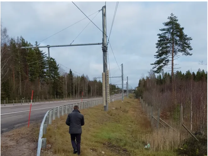
It is important to always perform geotechnical investigations early in the planning phase of the project. This way the stability and underground conditions will be known before the excavation begins and it is possible to plan where to place the support masts or other parts of the system, such as electrical cables. In Sweden, roadside safety barriers are usually installed along road stretches that are bordering steep slopes or water, or where obstructions such as rocks or poles are within the safety zone of the road. Along rural roads, the safety zone extends 10 m from the road edge. Safety barriers are needed if there are obstructions within this area that are more than 10 cm above ground level. As seen in Figure 1, safety barriers were needed for the overhead conductive system as the support masts have been installed close to the road edge.
Figure 1. Catenary poles and roadside safety barriers along E16, Sweden. Photo: Lina Nordin.
2.2. Road construction challenges – Conductive rail technology
There are several ERS concepts that build on the idea of conductive power transfer from some kind of rail technology that is installed in or on top of the road structure.
2.2.1. The In-road rail concept – Elways
The conductive in-road electric rail that Elways have developed is installed within the road structure and transfers energy via a pick-up beneath a vehicle. The rail consists of conductive metal and isolating plastic with a top-cover of steel. A 200 mm wide and 170–180 mm deep track needs to be excavated into the road structure. A base of macadam is laid under the rail structure and the gap between the rail and road structure is filled with a mastic asphalt. The rails need to be placed within reach of one of the power distribution boxes which are located within 1 500 m of each other (Asplund, 2017; NCC, 2014).
The rail at the demonstration site is 148 mm high and 144 mm wide and is constructed 3-5 mm below the road surface (Asplund, 2017). The rail is articulated every metre, which according to Asplund (Asplund, 2017) means that there will be no problem for the rails to follow the geometry of the road and still transfer energy. The opening in the rail (see figure 2) is narrow to prevent cycle wheels or animals from getting stuck. However, it is wide enough to allow sand and dirt to sediment at the bottom, and for small branches and leaves to get stuck in the rail.
The rail segments are only 12 m long to limit the risk for rail cracking (eRoadArlanda, 2018). Four segments of 12 m are connected to an input rail of 3 m, making each electrified rail section of the demonstration site, 51 meters long. The size is easily customised as the steel rails are placed within a concrete body, making it possible to modify the outside dimensions of the rail. Further improvements to the installation method include the use of geotechnical investigations early in the planning process. This will allow installation procedures to be adjusted according to the condition of the sub-grade.
The installation of the demonstration test site took nearly five month from the start of the installation of the ten switching boxes and the 10 000 m of power supply cables to the installation of the last piece of rail, where the installation of the 2 000 m of rails took about six weeks. This was, however, the first time such a solution was installed into a conventional road with a very basic road structure.
The installation procedure could be carried out more efficiently. It is possible to excavate the track using a road milling machine to cut the asphalt with an as straight cutting edge as possible. For a large-scale deployment, it will be necessary to perform geotechnical investigations before the installation begins.
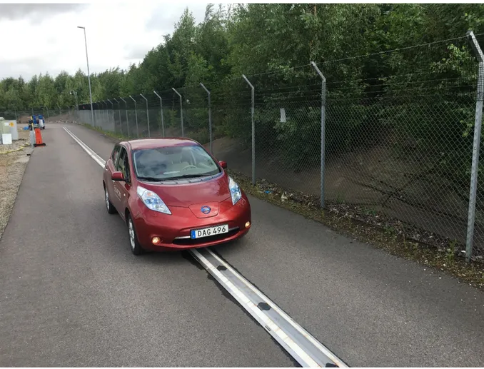
2.2.2. Evolution Road – On-road conductive rail technology
The concept from the company Elonroad consists of a rail laid on top of the asphalt. The rail is 38 mm high and 350 mm wide with sloped sides. The rail is mounted in 10 m long rail sections consisting of 1 metre long segments that are connected one after the other making a single rail. Each segment has a positive and a negative where the positive will only be switched on with the passing of a vehicle. The rail is attached to the asphalt via so called mounting plates that are glued or bolted on to the road surface. The rail is designed with 5 mm high rubber feet to allow water to flow under the rail. To provide power to the rails, power supply is required every kilometre. A transverse excavation track accommodates the power supply cable that is connected to the rail.
Figure 3. The Elonroad rail that will be used in the EVolution Road demonstration project in Lund. Photo: Dan Zethraeus.
The rails used in this technology are mainly made of aluminium, isolators, and copper. The rails have a life span of 10–20 years depending on service intervals (Zethraeus, 2017) and can resist unevenness, roughness in the asphalt, and up to 4–5 cm deep potholes (Zethraeus, 2017).
This concept is being tested in a new demonstration site in Lund in Sweden in 2020–2022. The first rail will be installed on the road surface. At the end of 2020, a rail that is submerged into the road structure will be constructed in the opposite lane for testing. The dimension of the submerged rail is 300 mm wide and 45 mm deep and is laid flush with the road surface. A milling machine will be used to excavate a 45 mm deep track in the asphalt layers. In comparison to the raised rail, the submerged version will be better suited for high speed roads where a raised rail could pose increased risks for motorcyclists. However, the submerged rail solution will cause issues regarding the durability of the road structure, similar to the in-road rail technology.
2.3. Road construction challenges – Inductive technology
Inductive technologies are interesting as they are completely embedded within the road structure. There will be no visible signs of an ERS hidden beneath the surface. This could be interesting as the road can be used in the same way as a conventional road and drivers will not need to alter their driving to locate a rail in the middle of the road or to connect to the overhead cable. The technology is
furthermore not visible to the regular road user and does not interrupt the visual perception of the landscape, as the overhead technology could. Apart from the rail technology, the embedded inductive technology will not interfere with the road surface hence no extra sealing routines are needed. It is however important to consider what will happen to the road structure with a technology that is constructed within the road structure as well as if construction joints for connecting electrical cables will be surface laid causing weak points on the road surface. It will, hence, be important to investigate what will happen during accelerated loading tests on a road with cables or coils embedded within the road structure.
One challenge for inductive ERS is the wireless power transfer efficiency which, according to Chen et al (2017), varies between 70% to 95%. They mention that inductive ERS will induce small electric fields that could cause electric energy losses due to electric polarization and slight conduction in the surrounding materials. They furthermore investigated the well-known fact that moisture could increase this kind of electric loss in pavement materials. If such electric loss would cause conductive heating of road materials, it might affect the characteristics of the structural layers within the road structure. According to (Bateman et al., 2018) the mechanical characteristics of a pavement can be affected by changes in factors such as strength, skid resistance, waterproofing and surface profile. Such changes could in turn lead to increased deterioration. As described by Chen et al (2017), such energy losses are probably very small and might not affect the road layers. Further investigations into what will happen with the technology and road structure during full scale testing with actual traffic loading will be required.
Sotirou (2014) investigated energy losses of inductive stationary technologies and concluded from model analyses that losses would be very small. However, this conclusion was for stationary inductive power transfer using Finite Element Models. It has not been tested in an actual road environment during accelerated or full-scale testing.
Generally, there are three different methods for constructing inductive systems - trench-based construction, micro-trench-based construction, and full-lane width construction.
2.3.1. Trench-based construction
With this type of construction, the inductive system is constructed either under the surfacing layers or surface-flush. The width of the trench can vary between 350 mm and 2200 mm. The depth is
determined by the depth of the bound layers (asphalt or concrete). The embedded coils are connected via electric cables below the bound layers leading to switching cabinets at the roadside. The coils are covered by back filling and asphalt layer of between 60 and 100 mm. This type of technology is used
Using trench-based construction methods can lead to cracking and deformation near the wheel paths and at the transverse joints where the coil is connected to the roadside power supply.
If the construction is surface-flush, the different materials on the road surface may result in variations in skid resistance. The formation of asphalt and concrete interfaces at the road surface can introduce weak points in the pavement structure. If damage occurs to the charging system, repairing or replacing the system will be very challenging. This means that, depending on the severity or type of damage, there could be a need to do a full depth excavation which can make this method very costly during its service life. Balieu et al (2019) also concluded that the volume of waste materials during the
excavation of embedded technologies is quite large.
2.3.1.1. Smart Road Gotland – Inductive technology
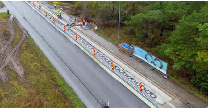
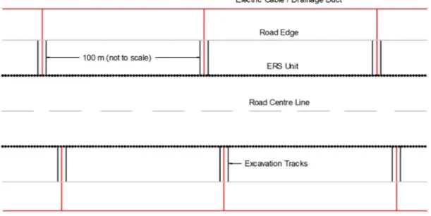
The inductive technology used in the Smart Road Gotland demonstration project is an inductive technology developed by Electreon. This technology is different to current inductive technologies as the coils, or the Stripe, only consist of copper and a rubber shielding. A shallow trench is excavated in the centre of the lane where the Stripe is installed 80 mm beneath the road surface. The Stripe is 1.5 m long and about 0.5 m wide. The Stripes are connected to a management unit at the roadside. Each management unit can manage 100 m of road. Figure 4 illustrates where the cables from each Stripe are gathered and led over to the side-verge.
Figure 4. Installation overview of the demonstration site on Gotland. Photo: Smartroad Gotland. The installation is described by Krauss (2019) to be quick. An asphalt milling machine excavates a shallow trench and a following vehicle installs the stripes and covers them with new asphalt material. For the installation to be quick it could be important to have a good knowledge of the road
construction and the sub-layers. So far, both ERS demonstration roads in Sweden, with installation within the road construction (the in-road conductive and the inductive technologies), have run into challenges when it came to excavating a trench in the existing road.
The project team of the Smart road Gotland demonstration project described the installation at Gotland during a presentation at the annual Swedish transportation conference, Transport Forum (2020). They mentioned that large rocks were encountered within the road construction, as well as varying
thicknesses of the road construction layers, both laterally and vertically. Such issues need to be considered before the installation.
With regards to inductive technologies, it is important to keep the vertical distance between the road coils and the vehicle receiver as constant as possible. This will help energy transfer to be as efficient as possible. The structural characteristics and the evenness of the road construction layers are important factors and should be considered at planning stages.
2.3.2. Micro-trench-based construction
Micro-trench-based construction has been developed as an alternative method to help avoid reflective cracking. Unlike the previous installation technique, this method requires very shallow and narrow trenches with widths between 20 to 30 mm and depths between 120 and 300 mm. With this method, the inductive system is contained in cables and placed in the excavated micro-trenches.
Like the previous method, the micro-trench-based construction method creates longitudinal and transverse vertical joints in the road structure. The challenge is to reinstate the micro-trenches with materials that can protect the embedded cables and resist against rutting, de-bonding, cracking, and water infiltration. It will also be very important to use highly resilient ducts to protect the coils and cables.
The depth of the embedded charging unit in the pavement is very important. This is due to the limited effective transmission distance between the charging unit and the receiver required to maintain efficient energy transfer. Hence, the system cannot be installed greater than a certain depth. This makes the cables prone to high levels of stress and strain from traffic loading (Bateman et al., 2014). In another study (van Bijsterveld and de Bondt, 2002), it was shown that embedding utilities such as tubes in the asphalt, would damage the asphalt pavements but also cause deformations on the tubes. This is also expected to happen around the wireless power units and electrical cables embedded within the asphalt pavement layers both for the conductive in road technologies and the inductive
technologies.
2.3.3. Full lane-width construction
With the full lane-width construction method, the full depth of the bound layers in one lane is
completely removed and the wireless ERS unit is installed either with in-situ, pre-cast, or prefabricated units. Electromagnetic field interfaces and shielding plates must be placed under the units for further protection from electromagnetic emissions. The coils are connected to the feed located at the side of the road and continue further to the roadside cabinets. The units are covered by a concrete layer. Finally, a 60 to 100 mm asphalt layer is laid on top of the concrete structure.
Due to the slow installation process, this method is expected to create more traffic disruption during the construction phase. Since the slab lengths are relatively short, the number of transverse joints created by this method is very high. Transportation of the slabs is an additional issue of concern and very disruptive to traffic.
ERS built with the full-lane-width method seem to be more robust than the other two methods but will require more maintenance and inspection on higher number of transverse joints. Furthermore,
maintenance that will require the excavation of the full-lane-width, may also have large impact on the adjacent lane.
Different solutions for maintaining road functionality are suggested in the literature and these may also be relevant for electrified roads. However, applying these solutions to electrified roads will require a great deal of consideration.
An additional asphalt layer at the top of the existing layer could be used to increase the overall
coil and the pickup unit in the vehicle. In terms of inductive energy transfer the distances between the sending coil in the road and the receiving pick-up in the vehicle will be critical for an efficient energy transfer. It is also important to note that this solution would increase construction costs.
Titi et al. (2003) and Bhosale and Mandal (2007) used porous asphalt structures to decrease stresses caused by a concrete unit. It is additionally important to maintain surface sealings with either hot bitumen, emulsion, or thin asphalt overlay to maintain good road functionality. Several studies also point to keeping the joint constructions in good condition (Chang and Lee, 2002; Mo et al., 2013; Partl et al., 2002) as well as considering different geometry designs to reduce the induced stresses at the joints (Chang and Lee, 2002; Park et al., 2011; Reid et al., 1998).
2.4. Impact on Road Construction from Embedded ERS technologies
Since both the conductive rail and inductive technologies are ERS technologies that are partly or fully installed within the road construction, they could impact the road structure in similar ways. This section describes possible impact issues or risks that could be relevant to in-road embedded technologies.2.4.1. Pavement joints
Installing charging units into existing pavements requires excavation. Any kind of excavation in existing pavements will result in the formation of both longitudinal and transverse joints. Depending on the width of the excavation, longitudinal joints can be formed near the middle or on the edge of the lane. To connect a power supply to the charging units, excavation or utility cuts are needed, causing transverse joints at regular intervals along the road section. The distance between the transverse joints will vary depending on type of charging system.
The pavement joints must be carefully constructed as poor construction can trigger different types of failure in the roads. Water ingress, unevenness, poor horizontal load transfer, and crack propagation are some of the failures that makes the careful construction of pavement joints very important.
2.4.2. Differences in thermal characteristics
ERS apparatus, in particular rail technology, is likely to be affected by thermal expansion and contraction. Differences in expansion properties will result in a de-bonding between the ERS
apparatus and the surrounding asphalt. Two main issues are buckling at the joint between two units as well as rail lift. Expansion and contraction movement must be confined within the ERS unit.
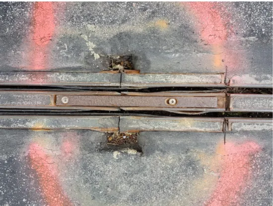
Figure 5 shows the joints in an early version of the in-road rail concept. The joints were repaired and improved to include a telescopic function making it possible for the joints to compensate for the thermal expansion during hot summers. This example proves the importance of having demonstration sites on actual roads and the improvements that can be made from resulting issues.
Figure 5. Joint between an early version of ERS rail units. Photo. Terence McGarvey. Excess heating from any part of the ERS apparatus during wintertime could cause thawing
mechanisms within the road construction. If this occurs when the road surface and surrounding road construction is frozen, hazardous conditions may arise. This issue needs to be further investigated for all types of ERS technologies that are fully or partly embedded in the road structure.
2.4.3. Material change within the pavement structure
Any material or stiffness change within the road structure, for example when installing inductive technology beneath the road surface or steel rails in the asphalt layers, can cause a concentration of stresses when the pavement is exposed to traffic and environmental loads. Stress concentrations are very likely to cause premature failures such as reflective cracking.
De-bonding at the interface between different materials, such as concrete and asphalt layers, can trigger premature failures in the pavement structure (Chabot et al., 2008; Vandenbossche and Fagerness, 2002). Such premature failures may take place where there is a discontinuity between an asphalt layer overlay and its concrete bottom layer due to a combination of traffic and environmental loads (Baek et al., 2010).
Another issue is the difficulty of combining rigid and flexible constructions. As the road is a flexible construction, the steel rail will, by being rigid, cause straining within the road construction during traffic loading on the rail. This is a common problem in areas where rails share the road with regular traffic, such as tramways in cities. Hedström (Hedström, 2004)mentions settlements, which could cause cracking or elevate areas of the road surface. Such settlements could cause irregularities that might impair the effectiveness of winter road maintenance as well as increase the need for other maintenance operations such as resurfacing. Bonding between the ERS apparatus and the surrounding asphalt is important when it comes to distributing traffic loading through the construction layers. If the bonding fails it could result in water ingress, deformation, and degradation of surrounding asphalt. It may lead to a concentration of loading at the bottom of the ERS unit or at the edge of the
2.4.4. Geometry
The design of the charging units protective shell can have a prominent impact on the performance quality and life span of the road. Sharp edges at the interface between the asphalt and concrete layers are a potential stress zone under braking and accelerating tyres. This could induce pavement surface damage on electric road sections. Chen et al. (Chen et al., 2019) showed with finite element modelling the potential of using charging units with optimised geometries for providing a better stress
distribution within the electric road structure.
2.4.5. Long term effects from loading
As described in a comprehensive report (Bateman et al., 2018), there is little available information on the long term impacts of ERS technologies. When reviewing existing literature, it is the finite element analysis that seems to provide the best indications of long-term impacts.
Chen et al (2019) used finite element models to investigate how traffic load on ERS roads with embedded inductive technologies could impact road construction. In their study they simulated the inductive ERS technologies by introducing a concrete box structure in their modelled road
construction. They showed that increased loading from heavy braking or acceleration would cause premature damage to the road construction. They suggested that this could be delayed if the bonding at the contact interfaces was sufficient.
Chen et al (2019) concluded in their study that by increasing the installation depth of the inductive ERS technology, from 5 cm to 8 cm, the stress concentrations within the road structure would decrease while the extent of permanent deformation and damage in the asphalt layer would instead seem to be increasing. They urge for precaution and a more holistic view before changing depths. So far, there is no documented information about monitoring and damages induced on existing ERS test sections or static inductive systems. However, the large number of pavement joints and material changes associated with ERS makes them very susceptible to damage. Carrying out systematic inspections is vital. It is expected that ERS will require more maintenance actions throughout their service lives.
2.5. Potential risks and suggested improvements
ERS apparatus placed within the road construction will disrupt the homogenous nature of the
structure. This will affect how traffic loading is distributed downwards into the substructure and could result in a concentration of loading at the bottom of the ERS apparatus. In certain circumstances, it is possible that the ERS apparatus will be greater in depth than the thickness of the asphalt construction layers. The ERS apparatus will transfer load directly onto the pavement’s unbound layers, which could cause severe deformation. In this case, it may be necessary to construct a concrete foundation
underneath the rails to distribute loading evenly onto the unbound layers. This could however be a costly solution if materials such as concrete are used.
Other suggestions that are under development include forming a stepped back construction of either the rail construction itself or the different road construction layers adjacent to the rail. This is further elaborated in section 2.5.1 and shown in figure 7.
2.5.1. Reinstatement improvements
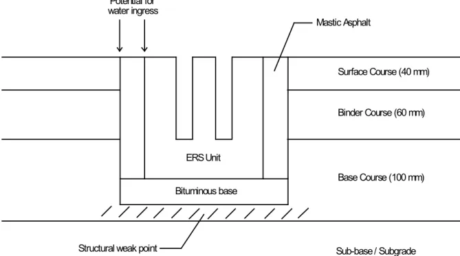
The construction detail shown in figure 6 was used for the demonstration project on road 893, near Arlanda airport. The ERS unit is 144 mm wide and 148 mm high. A 200 mm x 180 mm track was excavated into the road construction to accommodate the ERS unit. The unit was bedded on a layer of bituminous material. A dense, high bitumen content material was used as a reinstatement material.
ERS Unit Mastic Asphalt Bituminous base Binder Course (60 mm) Base Course (100 mm) Surface Course (40 mm) Sub-base / Subgrade (un-bound material) Potential for water ingress
Structural weak point
Figure 6. Construction method used for demonstration road.
The total depth of the ERS unit and bituminous base will typically be between 180 and 190 mm. Depending on the design of the road structure, the depth of bituminous material under the ERS unit and base, will vary significantly. In the example shown in figure 6, the remaining depth of base course is only around 20 mm. If the bond between the ERS unit and surrounding structure is compromised, loading will be transferred through the ERS unit (and base) onto the remaining base course. The remaining depth is unlikely to be enough to absorb and distribute the load. This will result in permanent deformation in the unbound sub-base or subgrade.
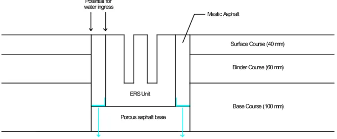
It is common practice that reinstatements for trench excavations should be stepped back. In the
following example, figure 7, the reinstatement has been stepped back 75 mm at each of the bituminous construction layers. It may be acceptable to step back the surfacing (surface and binder courses) as one layer.
ERS Unit
Porous asphalt base
Surface Course (40 mm) 75 mm 75 mm Base Course (100 mm) Binder Course (60 mm) Sub-base / Subgrade (un-bound material) Bituminous Material Joint compound
compound at a pre-determined frequency. This preventative maintenance measure will ensure that water ingress is eliminated or kept to a minimum.
2.5.2. Water Ingress and Drainage
There is a high likelihood that de-bonding will occur between the ERS unit and the reinstatement material. It is also possible that cracking will form at the vertical joint between the existing road structure and the reinstatement. De-bonding and cracking will allow surface water to penetrate the structure. The water will filter down and become trapped at the impervious bituminous base layer.
ERS Unit
Porous asphalt base
Sub-base / Subgrade (un-bound material) Mastic Asphalt Potential for water ingress Surface Course (40 mm) Binder Course (60 mm) Base Course (100 mm)
Figure 8. Proposed Construction detail – Drainage Improvement.
Water ingress in the road construction could be damaging to the road. Using conductive rail
technology that is partly embedded in the road increases the risks of water intrusion from the surface if the bonds between the rail and the asphalt are weak or damaged. It is important to consider an ERS construction method allowing water to drain at the bottom of the installed unit. In figure 8, a porous asphalt material is proposed as a base to the ERS unit. Allowing water to flow through the road construction layers is not desirable but this solution may be an acceptable compromise until the vertical joints are reinstated.
Vertical joints should be regularly inspected and repaired if de-bonding or cracking is apparent. So far, during the two years of demonstration at eRoadArlanda there has not been any apparent signs of settlements or loading damage of the rail. The project team have estimated that there are about 200 heavy goods vehicle passages every day along the road, and according to the Annual Average Daily Traffic (AADT) measurements there are about 1500 vehicles passing every day. This amount of time and traffic flow is not sufficient to provide an indication of any long term effects. Accelerated and full-scale testing are needed to provide data on how such an installation would impact the road
3.
Maintenance and operations
Maintenance and operation services for the national road network, are currently procured by the Swedish transport administration. The procured contractor must ensure that roads are operable and maintained to the specified standards. Specific contracts are set up to ensure that similar standards can be expected along a whole stretch of a road even though it might run through several different contract areas. Operations that are included in such base contracts (Trafikverket, 2017) can include winter maintenance, road sweeping, drainage works, clearing of side verge area, cleaning of rest areas, crack sealing, and re-grading. Some operations are performed regularly and others, such as pothole repair or crack sealing are performed on an as needed basis.
When discussing the different roles and responsibilities after the deployment of an ERS, the role of a road maintenance and operations contractor and the procurement of the road contract area will be crucial. It is suggested by Andersson et al (2019) that the proposed operator of the electric road should also be responsible for the road maintenance. However, this role is barely discussed in terms of road maintenance but rather focuses on the electrical operational activities. According to Andersson et al. (2019), to secure good operational safety it is important to have as few boundaries as possible between different actors. This is crucial to diminish the risks of conflicting operations. Nevertheless,
communication between different parties will be of huge importance.
Andersson et al. (2019) also suggest the possibility of having a specific ERS operator who can focus on the ERS infrastructure. This would allow the STA to concentrate on the road maintenance activities. However, this suggestion does not consider the various aspects concerning how different road maintenance activities could affect a specific ERS technology as well as the differences between the ERS concepts.
For the eHighway project on E16 outside Sandviken, the road maintenance contractor mentioned the risk of touching the overhead catenary cables with a vehicle’s lifting arm when performing an activity such as emptying rubbish at a rest area. The same risk occurs when cutting grass, as the cutting arm needs to be lifted every time the vehicle passes one of the support masts (Nylander, 2018).
Compared to conductive technologies, inductive technologies will possibly not create as many daily interactions between road and ERS. Interactions would occur when there is a need to repair cracks, carry out resurfacing, or perform drainage ditch activities. Risks would be associated to cutting or damaging the electric cables or apparatus embedded within the road structure or road-side area. ERS operators need to follow safety regulations when working along the roads. During cable
installation procedures, operators need to follow the rules and regulations that specify where and how to install electrical components within the road structure (STA, 2015; Zetterberg, 2017).
As the maintaining of safety levels and road quality are important requirements within a maintenance contract, it seems that it would be better if the ERS operations are included in the maintenance contract as well. Either way, there is an eminent need for road maintenance contracts that will involve ERS to take into account requirements from electrical safety regulations.
3.1. Electricity issues – supply, safety, electric work regulations,
installations
Even though ERS are only electrically live when a vehicle is using a specific part of the system, the electrical components could still pose a safety risk if something unexpected goes wrong. This means that when working close to or with those electrical parts or if there is an accident, it should be evident how to act.
railways (Andersson, 2019; Trafikverket, 2010). These consider the use of machines near live conductors. Machinery with lifting arms should be provided with height limiters. Machinery should not be operated closer than 1 m to live conductors unless they have protective earthing. In addition, an electrical work supervisor should always be present on site. As with all discussions concerning ERS, such regulations will depend on type of technology used.
3.2. Pavement structure reinstatements
Electric supply cables and drainage ducts will need to be installed across the carriageway for all ERS concepts that incorporate some sort of charging device in or on the road structure. Tracks or utility cuts will be excavated at regular intervals along the length of the ERS installation (as shown in figure 9). The distance between the cuts will vary depending on the type of ERS system and longitudinal low points.
Figure 9. Power supply and drainage duct plan.
It is difficult to construct utility cuts that are sustainable. Pavement structure reinstatements should be laid flush with the adjacent surfaces - no significant depression or crowning should be apparent. However, it is difficult to compact a reinstatement to the same levels as the surrounding pavement structure and this could lead to post compaction from traffic loading.
Surveys carried out in seven cities in Iowa, USA (Schaefer et al., 2005) indicated that utility cuts often lasted less than two years. It depended on how the cut was reinstated, what materials were used, climate conditions, and traffic. Several studies indicate that such cuts could reduce the life length of the road (Bodocsi et al., 1995; Tiewater, 1997). This indicates that an ERS road might need to be resurfaced more often than a conventional road. In some instances, it could even be as often as every two to three years as indicated in the Schaefer et al. study (2005), but such indications should be tested specifically at ERS roads.
It is, however, important to remember that such deterioration could be reduced if the whole lane is excavated when installing ERS, including the transverse connections. This would result in an even road structure along the whole road stretch.
When discussing maintenance activities such as resurfacing of ERS roads with rails installed in the middle of the lane, it will be important to consider any increases in work load and the requirement for new types of machinery. For example, removing pavement materials adjacent to the rail without damaging the rail. Paving machines might have to be smaller and new techniques might need to be
developed. Resurfacing activities will also have to be carried out on both sides of the rail. Such activities will take longer to complete and will subsequently cause longer periods of traffic disruption.
3.3. Comfort Levels
Road authorities will accept a certain amount of surface level variation provided it is within specified tolerance levels. This means that certain levels of edge depression, surface depression, and surface crowning could be apparent after a track has been reinstated. This will be experienced by motorists as a type of local unevenness.
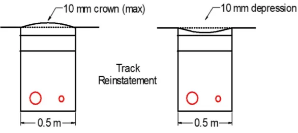
When trying to quantify this it might be typical to use the well-established International Roughness Index (IRI), which is commonly used to indicated roughness or uneven road surfaces. McGarvey (2019) used IRI to try and quantify the extent of such an unevenness that would appear from transverse cuts connecting wiring to embedded ERS technologies. IRI-values were calculated along simulated longitudinal profiles with repetitive surface irregularities.
The distance between the irregularities was 100 m. As tolerance levels for track reinstatements are not likely to be greater than 10 mm, the height or depth of the irregularities varied between -10 mm and 10 mm in each simulation. The width of the irregularity was 500 mm. The form of the irregularities was either surface depression or surface crowning (Figure 10). Consideration was not given to edge depression. Simulations were carried out for six sections with initial IRI levels ranging between 0.00 and 12.26 mm/m.
Figure 10. Track reinstatements.
The results showed that using this kind of method would probably average out the irregularities of a transverse cut as IRI is calculated over a longer length than the width of the irregularity. This view is supported by the maintenance standards (Trafikverket, 2012) which furthermore states that it is likely that surface irregularities of this type will not be detectable using 100 m IRI values.
A local unevenness measurement unit that could be used to complement existing longitudinal
measurements such as IRI. Local unevenness measurements would indicate the maximum unevenness value (0 -25 mm) over a 100 m long section (Lundberg et al., 2015). The maximum allowable levels of local unevenness would be based on the vertical acceleration created when a vehicle drives over a surface irregularity. As vertical acceleration is a function of vehicle speed, limits for local unevenness will be much lower on the high-speed road network.
It is expected that local unevenness adversely affects comfort and safety levels in a way that motorists will reduce speed until similar levels of comfort or safety are experienced (Ihs, 2005).
From a visual recording done by a researcher at VTI, driving a motorcycle along one of the ERS road stretches, it was clear that the transverse joints where the electrical cables or drainage ducts are installed, caused the suspension and damper of the motorcycle to work hard. The driver also
mentioned that unevenness was felt while driving. According to (Zetterberg, 2017), it is not permitted to install utility cables at such depths that they may cause settlements or elevation of the surface. It is suggested that cables that are laid transverse a road should be installed at least 1.5 metres below the road surface. Additionally, it is not permitted to cause freeze or thaw lifts or to install utility apparatus that will heat the road surfacing and reduce the level of friction.
The transverse joints with connecting cables could however also be laid in drainage ducts to remove water from the rail. Such drainage should be placed so that water run off can be infiltrated in the ditch or taken care of in some other infiltration facility.
Apparatus that is installed in the road structure may also be vulnerable to damage from works carried out in the road such as resurfacing activities etc.
The fact that such settlements caused by utility cuts are not allowed in the road makes the forthcoming years of ERS very interesting. Both rail and inductive technologies so far have used transverse utility cuts to connect power to the ERS apparatus. This could cause damage and settlement and such transverse connections need to be installed by excavating the whole lane instead of only where the connections are needed. Collaborations between manufacturers, road construction experts, and researchers are needed to solve these issues.
3.4. Wear and tear
There are very few studies regarding the wear and tear of ERS. The two demonstration projects in Sweden have been subject to some studies regarding the wear and tear of their respective technologies but those studies were based on limited testing of their own equipment. The tests cannot be compared to full-scale implementation with wear from regular traffic. Therefore, references have been made to similar transportation modes to get an understanding of what kind of wear that could occur in various ERS.
3.4.1. Catenary
For the catenary solution, wear and tear will occur in the pantograph collector strips and contact cable. If the wear and tear is significant it could result in very costly repair work (Shing and Wong, 2008). When objects or substances, such as ice, interrupt the energy transfer from the cable to collector strips, arcing appears as a bright light at the contact point between collector and cable. This kind of energy outburst will increase the rate of wear on the contact strips (Er and Çakir, 2018; Poetsch et al., 1997; Yang et al., 2012). Therefore, it is important to keep the cables and rails free from obstructions. Wu (2018) investigated the influence of electric current on contact resistance in the cables on a contact pantograph. This sliding electric contact plays an important part when it comes to the operation life of pantograph and cable systems. The study shows that, when there is a current in the cable, the heat generated increases the rate of wear on the cable. They also mention that arcing causes small pits or craters on the cable and this in turn could increase the risk of damage to the pantographs carbon strip. Increased wear of the carbon strip with increased temperature was also shown by Ding (Ding et al., 2012). This confirms that it is an important factor that should be considered before heating of the cable is used as a means of winter maintenance to melt frost or ice. In such case it could be more efficient to apply anti-icing agents on cables before peak hour traffic flows.
3.4.2. Conductive rail
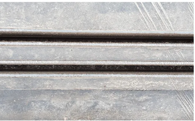
To the right in figure 11, there are clear scrape marks in the material surrounding the rail. This causes concern with regards to particles, wear of the rail, and whether energy transfer will be impaired if the rail is worn down too quickly. However, energy will be transmitted from contact surfaces further down in the track of the rail, hence some small scraping marks will not pose such problems. The question regarding particle emission from the wear, still remains to be answered.
Figure 11. Wear on the ERS conductive rail. Photo by Lina Nordin.
3.4.3. Inductive technologies
It might seem that the inductive technology is the best choice when it comes to wear and tear of the road surface and ERS equipment. It is however unclear what kind of wear they will pose on the road structure. Or if thick layers of snow or ice covering the road surface, would have an impact on the energy transfer. Early indications from the SmartRoad Gotland demonstration project indicated that during snowy conditions everything worked as planned. The system was able to transfer energy to a vehicle moving at 30 km/h (Electreon AB, 2020). It is not clear from the test data how much snow was laying on the road surface, hence further tests are needed to understand if snow depth could impact energy transfer. It is furthermore unclear if the embedded ERS will cause accelerated deterioration of the road structure, or how often the system will need to be repaired or replaced.
Some inductive technologies that has been in use for a few years, such as the OLEV and CIRCE installations, have shown increased rates of reflective cracking in the asphalt. Other types of inductive ERS technologies might be better suited for this because of a more soft and flexible construction compared to the concrete caskets that the OLEV technology is installed within. Still, if there is ERS equipment within the road structure there will be an increased risk for reflective cracking. Further studies and accelerated testing are needed to understand how much impact such technologies could have on road construction and durability.
Using finite element simulation, Chen et al. ( 2019) showed that embedded inductive systems could also cause damage within the road structure. If the system is embedded in a box-like installation