Mälardalen University Press Licentiate Theses No. 223
EVALUATION OF ROBOT STRUCTURES
FOR APPLICATIONS THAT REQUIRE HIGH PERFORMANCE,SAFETY AND LOW ENERGY CONSUMPTION
Bhanoday Reddy Vemula 2015
School of Innovation, Design and Engineering
Mälardalen University Press Licentiate Theses
No. 223
EVALUATION OF ROBOT STRUCTURES
FOR APPLICATIONS THAT REQUIRE HIGH PERFORMANCE,
SAFETY AND LOW ENERGY CONSUMPTION
Bhanoday Reddy Vemula
2015
Copyright © Bhanoday Reddy Vemula, 2015 ISBN 978-91-7485-239-4
ISSN 1651-9256
I
ABSTRACT
Emerging application areas, such as safe robotics and green robotics, greatly enable the extension of robot automation to new application processes in different industry segments. Successful realization of industrial robots for such application areas is highly influenced by the type of robot structure that is adopted for the design. Therefore, researchers have recently pursued new robot structures with improved characteristics resulting in the current availability of a wide variety of potential robot structures from which to choose.
Along with this, a difficult yet relevant challenge arises for robot designers to evaluate all the potential robot structures to select the best structure for new applications. This necessitates a need for tools or methods, which can aid robot designers or end-users to perform evaluation on robot structures in the early design stages. The research objective pursued in this thesis aims to address this need. To realize this objective, design knowledge must be advanced by providing methods and/or tools to quantitatively evaluate robot structures.
This project adopts research through design as a research methodology, which is based on the action-reflection approach in an experimenting setting. The experiential knowledge is gained on how to evaluate a set of two robot structures based on various requirements. This is done by carrying out simulation-based evaluation tasks on serial and parallelogram linkage articulated robot structures. Based on the acquired experiential knowledge, a simulation-based evaluation framework is proposed in this thesis, which can be used by robot designers or end-users to enhance the likelihood of selecting the most suitable robot structure for a new application process.
III
ACKNOWLEDGEMENTS
First and foremost, I would like to express my gratitude to Dr. Xiaolong Feng for recommending me for this research position.
Dr. Torgny Brogårdh, my industrial supervisor, has been a great mentor to me over the years, and I would like to express my appreciation for all his guidance. His expertise on industrial robots has been invaluable to this research project. I’d also like to give a heartfelt, special thanks to my supervisors, Dr. Björn
Fagerström, Dr. Giacomo Spampinato and Mikael Hedelind. This thesis is the
product of the many inspiring discussions I have had with them over the years. A big thank you to Dr. Giacomo Spampinato for taking the time to answer all my never-ending questions about the design aspects of industrial robots.
My gratitude is also extended to all my colleagues at the Division of Product Realization. Working together with you over the past three years has been a great experience. Special thanks to Professor Mats Jackson for providing an excellent learning environment within INNOFACTURE.
I thank Bengt Erik Gustafsson, for his assistance in and expertise in CAD, and Lasse
Frank for a fascinating illustration for the cover of this thesis. I would also wish to
thank Anita Chambers for editing this thesis.
I wish to thank Swedish Knowledge Foundation (KK-Stiftelsen), ABB Corporate Research and ABB Robotics for funding this research project.
Last, but certainly not least, I must acknowledge and express gratitude and deep thanks to my family and all my friends for their unconditional support and encouragement.
Bhanoday Reddy Vemula Eskilstuna, November 2015
V
APPENDED PAPERS
The following papers are appended and will be referred to by their Roman numerals. The papers are printed in their original published state, except for changes in formatting. In all three papers the first author is the main author; however, all the authors have contributed to the papers.
[ I ] Vemula, B. R., G. Spampinato, M. Hedelind, X. Feng and T. Brogardh (2013). “Structural synthesis of 3DOF articulated manipulators based on kinematic evaluation”. In Proceedings of 16th International Conference on Advanced Robotics (ICAR), 2013, IEEE.
[ II ] Vemula, B., G. Spampinato, T. Brogardh and X. Feng (2014). “Stiffness Based Global Indices for Structural Evaluation of Anthropomorphic Manipulators”. In Proceedings of 41st International Symposium on Robotics; Proceedings of ISR/Robotik, 2014, VDE.
[ III ] Vemula, B., G. Spampinato and T. Brogardh (2015). “A methodology for comparing the dynamic efficiency of different kinematic robot structures”. In Proceedings of IEEE International Conference on Mechatronics and Automation (ICMA), 2015, IEEE.
VII
LIST OF ABBREVIATIONS
3D: 3-Dimensional DOF: Degree of Freedom EM: Evaluation Method IRB: Industrial Robot
IFR: International Federation of Robotics ISO: International Standardization Organization LWIR: Light Weight Industrial Robots
OA: Optimal Area
P-Link: Parallelogram Linkage
PHRI: Physical Human Robot Interaction P: Prismatic
R: Revolute
RPA: Relative Performance Average RPM: Relative Performance Maximum
IX
1
Introduction ... 1
1.1 BACKGROUND ... 1 1.2 PROBLEM STATEMENT ... 3 1.3 RESEARCH OBJECTIVE ... 4 1.4 RESEARCH QUESTIONS ... 4 1.5 DELIMITATIONS ... 51.6 OUTLINE OF THE LICENTIATE THESIS ... 5
2
Research Method ... 7
2.1 DESIGN RESEARCH ... 7
2.1.1 Design research approaches ... 7
2.2 RESEARCH CONDUCTED BASED ON DESIGN RESEARCH ... 8
2.3 RESEARCH PROCESS ... 8
2.3.1 Theoretical knowledge - Literature review... 10
2.3.2 Simulation-based experience ... 10
2.3.3 Reflective observations ... 11
2.3.4 Abstract concepts and generalization ... 11
2.3.5 Verification of the abstract concepts ... 12
3
THEORETICAL FRAMEWORK ... 13
3.1 INDUSTRIAL ROBOTS ... 13
3.1.1 Mechanical systems ... 14
3.1.2 Robot manipulator design ... 15
3.2 CLASSIFICATION OF ROBOT MANIPULATOR TYPES ... 16
3.3 REQUIREMENTS ... 17
3.3.1 Requirements for task-based application areas ... 18
3.3.2 Requirements for safety-based application areas ... 19
3.3.3 Requirements for energy efficiency-based application areas ... 20
3.4 PERFORMANCE INDICES ... 21
3.4.1 Classification of performance indices ... 22
3.4.2 Examples of performance indices ... 23
3.5 DESIGN PARAMETERS ... 28
3.5.1 Geometrical parameters ... 28
3.5.2 Structural parameters ... 28
3.5.3 Elasto-dynamic parameters ... 29
3.6 EVALUATION METHODS ... 29
3.6.1 Fuzzy reasoning approach ... 29
3.6.2 Optimization approach ... 29
3.6.3 Optimum performance region approach ... 30
3.7 LITERATURE SUMMARY ... 30
X
4
Evaluation methods and Analysis ... 35
4.1 EVALUATION METHOD BASED ON SINGLE-OBJECTIVE OPTIMIZATION APPROACH ... 36
4.1.1 Application example: ... 36
4.2 EVALUATION METHOD BASED ON A MULTI-OBJECTIVE OPTIMIZATION APPROACH... 37
4.2.1 Application example ... 38
4.3 EVALUATION METHOD BASED ON RELATIVE WORKSPACE EVALUATION APPROACH ... 39
4.3.1 Application example ... 40
4.3.2 Relative workspace evaluation method—3D version ... 41
5
Discussion ... 45
5.1 PERFORMANCE INDICES ... 45
5.2 DIMENSIONING THE DESIGN PARAMETERS ... 46
5.3 EVALUATION METHOD ... 46
5.3.1 Evaluation situations ... 46
5.3.2 Simulation based evaluation framework ... 47
5.4 REASSESSING THE RESEARCH QUESTIONS ... 48
6
Conclusions and Future work ... 51
6.1 CONCLUSION ... 51
6.2 FUTURE WORK ... 51
7
References ... 53
8 Appended Papers ……….
XI
TERMINOLOGY
Engineering Design: “Engineering design is the process of applying various techniques and scientific principles for the purpose of defining a device, a process, or a system in suffecient detail to permit its physical realization”(Taylor 1959) Evaluation: “An evaluation is meant to determine the ‘value’, ‘usefulness’ or ‘strength’ of a solution with respect to a given objective. An evaluation involves a comparison of concept variants or, in the case of comparison with an imaginary ideal solution, a ‘rating’ or degree of approximation to that ideal.”(Pahl and Beitz 2013, p. 110)
Design Parameters: Design parameters are the actual quantities, which define the physical and functional characteristics of the designed system, product, or component.
Design Characteristics: The design characteristics are the attributes that express the properties of the design.
Performance Indices: “Performance indices are metrics designed to measure and quantify the different performance characteristics of a robotic manipulator in its workspace.”(Patel and Sobh 2014, p. 548)
Best- or Optimal-value or Solution: In engineering design, one can usually not be certain that an absolute best or optimal value or solution is obtained. Nevertheless, best or opimal solutions are pursued in this thesis since these usually constitute good approaches.
1
This chapter gives an introduction and background to the research project. The research need for tools or methods for evaluating robot structures in the initial stages of the industrial robot design process is presented. Finally, the objectives of the research project are stated.
1.1 BACKGROUND
“Industrial robotics is the discipline concerning the robot design, control and application in industry”(Siciliano, Sciavicco et al. 2009, p. 15). Industrial robots have reached the level of a mature technology and are used for executing a large number of application processes in different industries. The main factors influencing this wide usage are reduction of manufacturing costs, achievement of higher productivity and consistent quality and improvement of work conditions and safety for the human operator (Hedelind 2008). However, there is still a huge scope for further extending robot automation to new application processes, which are currently constrained by the technological limits of the robot itself.
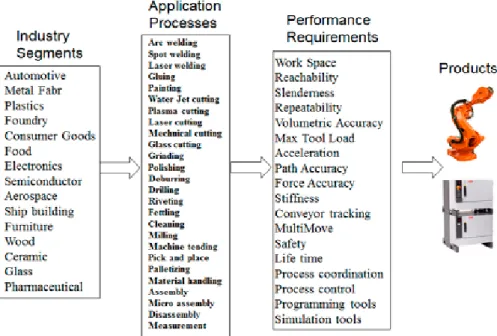
Industrial robots need to fulfill different sets of performance requirements to execute various application processes. Sometimes, even if the processes that the robots need to perform are the same, different industries will have different requirements on how to perform the processes and how to install the robots and what type of equipment that the robots will work with. Thus, robot design is a very complex activity in order to obtain robot performance that can be accepted by as many application process and industries as possible. Figure 1 shows examples of industry segments, robot application processes and robot performance requirement features that designers must consider.
Emerging application areas, such as safe robotics and green robotics, enable the extension of robot automation to new application processes in different industry segments. In both instances the use of lightweight industrial robots (LWIR) is very important. For green robotics the lowest possible power is needed to actuate the robot joints, meaning the lightweight arm system. For safe robotics the lowest possible impact is needed in the event of collision between a robot and its surrounding environment and the requirements are especially difficult to obtain for collisions between robots and humans. If it is possible to secure harmless collisions between robots and human, it will be possible to obtain human/robot collaboration when the robot runs on high performance. It will also be possible to use robots without fences, which will save installation cost and floor space. Therefore, for emerging application areas, robot designers need to consider
2
requirements related to safety and energy efficiency in addition to the process-based performance requirements given in Figure 1.
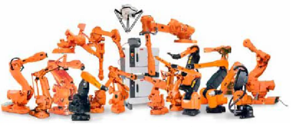
In general, an extensive robot family is needed to cover a large number of robot applications as seen in Figure 2. When a new robot application appears, the first task is to see if it is possible to use an existing robot. If this is not possible, redesigning an existing robot structure within the robot family is tried and if this is neither feasible, new robot structures must be sought. For example, this process led to the development of a very fast pick and place operation in the food industry, and for this a new robot concept with parallel kinematics (ABB IRB 340 Flex Picker) was created. Recently, researchers have actively pursued new robot structures with improved characteristics. This has resulted in the growth of robot families among manufacturers as well as an increasing number of conceptual robot structures reported in the literature (Tsai 1999).
Evaluation of different robot structures is a difficult but necessary task (Joshi and Tsai 2003; Wu, Wang et al. 2010; Zhao, Chen et al. 2013). Providing tools and methods to allow robot designers or end-users to quantitatively compare robot structures is indeed necessary, because the variety of existing robot structures makes it hard to choose which one is best suited for a specific task or for a new application process (Chablat, Wenger et al. 2004).
This research considers methods to be used to select the best robot structure for a new application. Looking, for example, at the robots in Figure 2, how can one
Figure 1. Examples of industry segments, robot application processes and robot performance requirements
3
select the robot structure with the lowest power requirements for a given set of application requirements? How can one select a robot that can perform a set of applications while simultaneously fulfilling the safety requirements for human robot collaboration? This research proposes a method to support such robot selection. The method compares two robot structures at a time and to do this. A set of input data is used to simulate the robots and a set of output data is obtained to benchmark the robots relative to each other. For example, input data could be speed and acceleration at different tool positions in the work space, and output data could be the joint torques or joint powers needed at different tool positions.
1.2 PROBLEM STATEMENT
To select the most appropriate robot structure for new application processes, evaluation of all the alternative structures needs to be done by considering requirements from multiple application areas. Then performance data corresponding to each robot structure needs to be treated for performing quantitative comparison. However, one type of robot structure exhibiting superiority for all the considered evaluation criteria is seldom found. Adding to the complexity, the degree of suitability of a given robot structure often depends on where in the workspace most of the tasks will take place.
Previous research has been directed at addressing the individual aspects of the robot selection issues (Inoue, Takano et al. 1993; Miomir, Veljko et al. 2001; Joshi and Tsai 2003; Chablat, Caro et al. 2010; Wu, Wang et al. 2010; Zhang, Gao et al. 2012; Zhao 2013). However, very few studies have been reported that aim at addressing these issues holistically; hence, very few formalized evaluation methods exist in the literature or in practice. Therefore, there is a need for research to develop evaluation methods, which can aid the robot designer in the early stages to identify the best robot structure among a given set of alternatives for extending the robot automation to new application processes.
4
1.3 RESEARCH OBJECTIVE
The objective of this research is to develop an evaluation method, which can be applied in the early stages of the design process, for selecting the most suitable robot structure for executing new processes in emerging application areas.
1.4 RESEARCH QUESTIONS
The first step in any evaluation process is to derive detailed and quantifiable evaluation criteria based on a set of desired requirements (Pahl, Beitz et al. 2007). When evaluating robot structures, their performance characteristics, which indicate their abilities or traits to meet the desired requirements, need to be quantified and used as evaluation criteria. Hence, in order to address the research objective, there is a need to gain knowledge of techniques to quantify the performance characteristics. This forms the basis for the formulation of the first research question.
RQ1. How can the performance indices be identified when evaluating different robot structures?
The dimensions or values assigned to the design parameters of a given robot structure can influence the merit of different performance characteristics of the given robot structure in different ways. Also, adding to the complexity, a given set of design parameters may not result in the best or most optimal values of a specific performance characteristic in different robot structures. Hence, there is a need to gain knowledge of how to treat the design parameters corresponding to different robot structures when evaluating them. This forms the basis for the formulation of the second research question.
RQ2. How can values be assigned to the design parameters when evaluating different robot structures?
Robot structures are required to fulfill different performance requirements depending upon their areas of application. Realizing requirements from one application area might conflict or complement or be neutral to the realization of other requirements from the same or different application areas. Hence, there is a need for increased knowledge of how to evaluate robot structures by considering different requirements. This forms the basis for the formulation of the third research question.
RQ3. How can different robot structures be evaluated with respect to requirements of application areas that need high performance, safety and low energy consumption?
5
1.5
DELIMITATIONS
The state of the practice was observed from only one robot manufacturer’s perspective. This implies that the researcher is unaware of unreported existing evaluation methods which are currently practiced by other robot manufacturers. Research findings reported in this thesis were obtained through the action-reflection approach (see Chapter 2). Therefore, the research findings consist of abstract concepts and generalizations derived from the reflections of the evaluation tasks performed by the researcher in the research project.
The methods proposed in this thesis can be validated by applying different evaluation tasks for different types of robot structures. However, in this research project the proposed methods were only verified for two robot structures with respect to safety and energy saving, where actuator torque and power are the most important performance characteristics.
1.6 OUTLINE OF THE LICENTIATE THESIS
This thesis is divided into six main chapters.Chapter 1 gives an introduction to the research area. The importance of carrying out an evaluation process for selecting suitable robot mechanical structures for new application processes is discussed. The research objective and research questions are stated.
Chapter 2 presents the research approach and methods applied in this research. Chapter 3 presents a literature overview, which points out the state-of-the-art in design, analysis and evaluation of robot manipulators.
Chapter 4 refers to the appended papers and presents by means of examples evaluation methods studied in this research project. The examples include the evaluation tasks carried out on serial and parallelogram linkage anthropomorphic robot structures.
Chapter 5 discusses the research findings and addresses the research questions. Chapter 6 includes the conclusion and proposals for future research.
7
To realize the objective of this thesis (Section 1.3) new information is needed in order to answer the formulated research questions (Section 1.4). This necessitates the need for a systematic search and acquisition of knowledge related to design and design activities, for which design research becomes necessary (Bayazit 2004).
2.1 DESIGN RESEARCH
Design research as defined by (Archer 1981)"… is systematic enquiry whose goal is knowledge of, or in, the embodiment of configuration, composition, structure, purpose, value and meaning in manmade things and systems”(p. 31). Research activities related to design are explanatory in nature, and provide a means for producing new information (Downton 2003; Cross 2006).
2.1.1 Design research approaches
(Frayling 1993) in the design/research conference at the Royal College of Art in London stated that designers undertake research as a part of their design and analysis activities and as an inherent aspect of their design synthesis activities. He further claimed that works of design can also be attributed to the works of research. Henceforth, the following three approaches of design research have found prominence. (Cross 1995; Findeli 1998; Jonas, Meyer-Veden et al. 2004). Research for design: As described by (Archer 1995), “There are circumstances where the best or only way to shed light on a proposition, a principle, a material, a process or a function is to attempt to construct something, or to enact something, calculated to explore, embody or test it”(p. 11). The research for design approach can be adopted under these circumstances. Hence, this approach is often called action research or practice-led research.
Research through design: In this kind of research, new knowledge is created through an action-reflection approach, where the emphasis is on the research objective of creating new design knowledge rather than the product/artifact for consumption. This research is also commonly referred to as project-grounded research or research-oriented design (Jonas 2007). The most important aspect of this approach is that it intends to provide design knowledge within a broader context, which can be applied in future design activities.
Research about design: In this area, research is carried out about design (i.e. about its history, its objects, its designers, its meaning and significance for business, society, end-users, etc.) by researchers whose main goal is to produce new knowledge in the fields of anthropology, archeology, psychology, etc., and not particularly in the design field. The method of scientific enquiry underlying this form of design research has ranged from philosophical analysis through case studies and interviews to protocol studies (Cross 1995).
8
2.2 RESEARCH CONDUCTED BASED ON DESIGN RESEARCH
In this project, the researcher’s emphasis is not on evaluating a particular set of robot structures or designing a robot system for a particular application process, but rather the emphasis is on creating new design knowledge on how robot structures can be quantitatively evaluated. Therefore, research has been conducted using the research through design approach.
This is an applied research project, where the design knowledge is created through an action-reflection approach, and the acquired knowledge is intended to be useful for future design activities. For validity, this research has considered the following validity criteria.
Purposive: The purpose of conducting this research is to address the design problem, which is described in the Section 1.2.
Inquisitive: This research study intends to acquire new design knowledge in order to address the research questions listed in Section 1.4. These questions drive the process by establishing measurable criteria on the goals and objectives of the research.
Informed: This research attempts to build on the existing theoretical foundations described in Chapter 3. The acquired design knowledge from this research is put into a wider context by aligning it with existing information (Chapter 5).
Methodical: The methods used for collecting and analyzing data in this research are presented in Chapter 2. The research process and methods used in this research project are described in Section 2.3
Communicable: Validity and verification aspects of the research findings are discussed in Section 2.3.5.
These criteria (borrowed from (Cross 1995) were adopted from Archer (1981) and could be applied as criteria for research through design, as well as research for design and research into design.
2.3 RESEARCH PROCESS
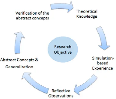
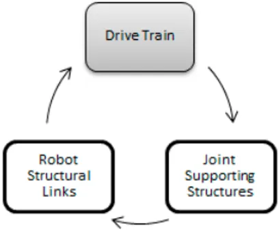
This research was carried out based on the experiential research cycle represented in Figure 3. This methodology was inspired from Kolb’s experiential learning theory (Kolb 1985), which is typically expressed as a four-stage cycle of learning. In this theory, concrete experiences provide a basis for observations and reflections, which are assimilated into abstract concepts that can be actively tested, and, in turn, create new experiences. Kolb’s learning theory is mainly practiced by educators to enhance the individual learning styles of students or young people. Since the researcher had no prior working experience or state-of-the-art-knowledge related to robot system design, aspects of Kolb’s learning theory have been incorporated into the research methodology to enhance the personal
9
knowledge of the researcher by gaining concrete experience. During this process, the researcher identified design challenges that required new information to realize the research objective. To produce this new information, research through design based on an action-reflection approach was employed.
Therefore, in this study, Kolb’s experiential learning theory was adopted and modified into an experiential research cycle (see Figure 3) such that it meets the criteria of the design research described in (Section 2.2). The research process followed in this thesis will be described based on the following stages of the experiential research cycle:
1. Theoretical knowledge: In this cycle the learning process starts by acquiring theoretical knowledge on various aspects related to the methods for evaluating two robot structures.
2. Simulation-based experiences: In the second step the researcher takes the designer’s role and applies the acquired theoretical knowledge to address a specific design task (the task of evaluating a set of two robot structures) by actively involving himself to gain experience.
3. Reflective observations: In this step, the researcher steps back from the design task and takes the researcher’s role in order to critically review what has been done and experienced. At this stage, the observations made are communicated with the industrial end-users and research
Figure 3. Experiential research cycle (adapted and modified from Kolb 1985)
10
community for external reflections on the observation, thereby enabling co-production between industry and academia.
4. Abstract concepts and generalization: This stage involves the process of assimilating reflective observations into abstract concepts and generalizations (design theory).
5. Verification of abstract concepts: Abstract concepts must be tested by solving design tasks in new situations and should be documented and communicated with the experienced industrial engineers and research community for verification. This learning cycle is iterated until the research objective is realized.
2.3.1 Theoretical knowledge - Literature review
Theories, methods, frameworks and models related to the design processes and evaluation procedures of robot structures have been reviewed from the literature. The applicable information was searched using various databases (Scopus, IEEE Explore, Science Direct, and Google Scholar). This was accomplished by using keywords, which were relevant to the research questions, and thereby identifying the researchers and their studies, which are collinear to this thesis. The following books, journals and conferences represent some of the most important reference sources in this literature review (Chapter 3).
Books:
1. Robotics: Modelling, Planning and Control 2. Robot Dynamics and Control
3. Springer Handbook of Robotics Scientific Journals:
1. International Journal of Robotics Research 2. IEEE Transactions on Robotics
3. IEEE Robotics and Automation Magazine 4. Journal of Intelligent and Robotic Systems
5. Robotics and Autonomous Systems International Conferences:
1. IEEE International Conference on Robotics and Automation
2. IEEE/RSJ International Conference on Intelligent Robots and Systems 3. International Conference on Advanced Robotics
4. International Symposium of Robotics Research
5. ASME, International Design Engineering Technical Conference.
2.3.2 Simulation-based experience
Information related to various aspects of the evaluation procedure from the theoretical foundations is applied to solve a specific evaluation task. This task
11
involves evaluating serial and parallelogram linkage (P-Link) structures on the basis of requirements from different application areas. This application step is done by adopting the simulation method.
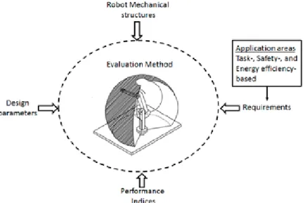
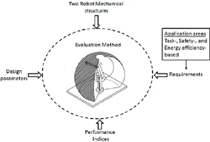
Simulation Method: As illustrated in Figure 4, applicable data from theoretical foundations is used to build robot system models. (Modeling as described in the appended papers is done for both serial and P-Link robot structures considered in the evaluation tasks.) This transforms input information into output information by using a simulation method. Input information includes the dimensions or values assigned to the design parameters (Section 3.5) and output information includes the merit or values of the performance indices (Section 3.4) on the basis of which two robot structures can be evaluated quantitatively. Three evaluation procedures were applied to perform three different evaluation tasks, which are described in Chapter 4. This was done to gain concrete experience in the evaluation methods.
2.3.3 Reflective observations
The simulation-based experience gained from different evaluation tasks is reflected by the researcher and the observations related to the quantification of performance characteristics, dimensioning of the design parameters and the overall evaluation methods are described in Sections 5.1, 5.2 and 5.3. Reflections in this research involve the analysis of evaluation methods which are adopted to carry out different evaluation tasks. The conclusiveness with which an evaluation method can facilitate robot structure selection in a given evaluation task is reflected in this research (See Chapter 4).
2.3.4 Abstract concepts and generalization
The experiential knowledge assimilated from the reflective observations was generalized and aligned with the existing theoretical knowledge. Subsequently, the knowledge gained from this action-reflection research process is used to address the research questions (Section 5.4).
12
2.3.5 Verification of the abstract concepts
As described by (Buur and Andreasen 1990),a design theory can be verified either by logical verification or verification by acceptance.
Verification by logic: This implies that the theory should not have any inherent conflicts between its internal parts, that it is complete and in agreement with the other theories in the field. The proposed methods can be verified by applying them in different evaluation tasks. If successful, it indicates that the proposed methods are internally consistent and capable of solving evaluation tasks of different types of robot structures. However, in this research project, due to the time constraints, the proposed methods have not been verified by applying different evaluation tasks. This needs to be done in the future to verify the validity of the research findings.
Verification by acceptance: This implies that experienced users in industry or the research community should accept the proposed theory. The usefulness of the proposed evaluation methods needs to be further verified by acceptance of experienced engineers working in the field. Nevertheless, all the appended papers were subjected to full reviews by other researchers before being accepted.
13
This chapter presents a brief literature review, highlighting the exiting knowledge on design aspects related to the evaluation of robot structures, on which this research is based.
3.1 INDUSTRIAL ROBOTS
“Industrial robot is a machine with significant characteristics of versatility and flexibility”(Siciliano, Sciavicco et al. 2009, p. 17). This has had a tremendous impact on the manufacturing industry ever since the Unimate industrial robot was installed in 1961 due to the pioneering technical work by George Devol and robot business development by Joseph F. Engelberger.
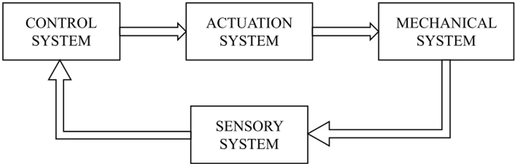
According to (ISO 8373: 2012), the “industrial robot is an automatically controlled, reprogrammable, multipurpose manipulator programmable in three or more axes, which can be either fixed in place or mobile for use in industrial automation applications” (General terms, para. 1). With reference to this definition, a robotic system is a complex structure, which can be functionally represented by multiple subsystems as presented by (Siciliano, Sciavicco et al. 2009) in Figure 5.
The mechanical system consists of various mechanical components that enhance the robotic system with the capabilities of locomotion and/or manipulation. The actuation system enables the animation of these mechanical components. The sensory system is responsible for acquiring data relating to the internal status of the mechanical system as well as the external status of the work environment. This data is used to enhance the perception capabilities of the robot. Subsequently, the capability of connecting action to the perception in an intelligent fashion is enabled by the control system (Siciliano, Sciavicco et al. 2009). Therefore, robotics can be judged as a critical technology (Thurow 1996) involving a broad spectrum of front running technologies related to multidisciplinary subjects concerning mechanics, electronics, sensors, computers and control. Thus it is considered to be a classical representation of mechatronics.
3
THEORETICAL FRAMEWORK
CONTROL
SYSTEM ACTUATION SYSTEM MECHANICAL SYSTEM
SENSORY SYSTEM
Figure 5. Components of robotic system as represented in (Siciliano, Sciavicco et al. 2009, p. 3)
14
This research project intends to contribute to the area of mechanical systems. Hence, the relevant theoretical foundations related to the design of the mechanical systems will be briefly reviewed in this chapter.
3.1.1 Mechanical systems
Mechanical system design is a key feature in the robot realization process. Mechanical systems which are only capable of manipulation are classified as robot manipulators and those with both locomotion and manipulation capabilities are referred to as mobile robots (Siciliano, Sciavicco et al. 2009). The area relating to the realization of mechanical systems of robotic manipulators will be briefly reviewed in the remainder of this chapter, while mobile robots are considered to be beyond the scope of this thesis at the present stage.
Robot Manipulators
According to (ISO 8373: 2012), “manipulator is a machine in which the mechanism usually consists of a series of segments, jointed or sliding relative to one another, for the purpose of grasping and/or moving objects (pieces or tools) usually in several degrees of freedom” (General terms, para. 9). Based on this definition, the mechanical system of robot manipulators is characterized by its arm and wrist. Each of these mechanical components are essential in accomplishing the manipulation tasks, which include the movement of a work piece or tool from one point to another with required orientation, trajectory and speed (Warnecke, Schraft et al. 1999).
Arm: The mechanical structure of the arm is composed of a sequence of links interconnected by revolute (R) or prismatic (P) joints that together form a kinematic chain. When there is only one sequence of links connecting the two ends of the kinematic chain, it is termed as an open kinematic chain. When the sequence of links forms a loop, it is considered to be a closed kinematic chain. In an open kinematic chain, each joint provides the mechanical structure with one actuated degree of freedom (DOF). In the closed loop kinematic chain the number of actuated DOFs is less than the number of joints (Siciliano, Sciavicco et al. 2009). A robot manipulator arm requires three actuated DOFs, in order to support and position the robot wrist and end-effector in the three-dimensional (3D) work environment.
Wrist: This is a combination of joints between the arm and the end-effector that primarily enables the orientation of the end-effector in the work environment (Warnecke, Schraft et al. 1999). A robot manipulator wrist requires three DOFs provided by three actuated revolute joints in order to arbitrarily orient the end-effector in a 3D work environment.
End-Effector: This is a tool that is generally located at the end of the robot wrist and enables the robot to interact with the environment in order to perform the
15
required tasks, such as grasping, welding, painting, pick and place, etc.(Warnecke, Schraft et al. 1999).
Workspace: “The workspace represents the portion of the environment the manipulators end-effector can access”(Siciliano, Sciavicco et al. 2009, p. 4). The shape and volume of the workspace depend on the mechanical structure of the arm and also on the joint angle limits. The workspace is often classified into reachable and dexterous workspace. Reachable workspace represents the entire set of points in which the robot can position its end-effector. Dexterous workspace consists of those points where the manipulator can position the end-effector with an arbitrary orientation (Spong and Vidyasagar 2008).
3.1.2 Robot manipulator design
The design of robot manipulators consists of the following two main phases (Merlet and Gosselin 2008).
Structural synthesis: The first task in the structural synthesis phase is to identify and cluster all possible mechanical structures that enable a specific class of work-piece motion, which is needed for executing various tasks pertaining to a given application area. Subsequently, the designer determines the most suitable mechanical structure from the cluster of alternative structures based on its abilities to also meet other performance requirements, such as max speed, max acceleration, positioning accuracy etc., in addition to the motion pattern of the end-effector (Merlet 2005; Zhao 2013).
Dimensional synthesis: In this phase, the designer’s task is to determine the geometrical, structural, dynamical and stiffness data related to the chosen mechanical structure (Merlet 2005; Zhao 2013). In this dimensioning process, the designer makes use of performance characteristics, which quantitatively express the ability of the robot design to meet the performance requirements. Performance characteristics (indices) are dependent variables to which the designer cannot directly assign values, but works with through some of the design parameters. Such design parameters correspond to design variables, whose values the designer needs to adjust in order to realize or improve the robot performance (Andersson 2001).
Evaluation of robot mechanical structures:
Essentially, a well dimensioned robot, employing any one of the alternative mechanical structures, will, in most cases, outperform a poorly dimensioned robot with a mechanical structure that is most appropriate among its alternatives for the given task (Merlet and Gosselin 2008). Therefore, structural synthesis cannot be disassociated from the dimensional synthesis, especially when the designer attempts to evaluate all the candidate robot mechanical structures for a given application area. The remainder of this chapter briefly reviews the theoretical foundations related to the different types of robot mechanical structures,
16
performance requirements pertaining to different application areas, performance indices, design parameters and evaluation methods for determining the most suitable mechanical structure in the structural synthesis process.
3.2 CLASSIFICATION OF ROBOT MANIPULATOR TYPES
Classification of robot manipulators is very useful in determining which type of robot is appropriate for the intended application. Generally, the choice of the mechanical structure, the power source for actuating the joints, the methods that the controller adapts to guide the end-effector and the intended application tasks of the robot manipulator are all closely interrelated. Therefore, robot manipulators could be classified based on the mechanical structure, power source, the method of control or the application area (Spong and Vidyasagar 2008). Nevertheless, since 2004, (ISO 9283:1998) has classified industrial robots only by their mechanical structure (Dinwiddie 2015). The types of robots as listed in (Robotics 2014) are as follows.
1. Linear robots 2. Cylindrical robots 3. SCARA robots 4. Articulated robots 5. Parallel robots
In this section, the types of robots listed above will be reviewed from the descriptions provided by (Spong and Vidyasagar 2008; Siciliano, Sciavicco et al. 2009).
Linear robots (PPP): Linear robots include both Cartesian and Gantry robots. Cartesian robots contain three prismatic joints whose axes are mutually orthogonal to each other. Each DOF corresponds to a Cartesian space variable and, therefore, it performs joint-wise linear motions in space. Cartesian robots, in general, exhibit good mechanical stiffness, high mechanical Eigen frequencies and isotropic positional accuracy throughout its workspace. Nevertheless, due to the presence of prismatic joints, it has lower dexterity. If the application requires the objects or tools to be approached from the top, the Cartesian structure can be mounted on a Gantry structure. Typical applications of linear robots include material handling, machining and assembly.
Cylindrical robots (RPP): The first joint of the cylindrical robot is revolute and produces rotation about the base, while the second and third joints are prismatic. As the name suggests, all three axes form a cylindrical coordinate system. Cylindrical structure offers good mechanical stiffness. However, the positional accuracy is not isotropic throughout its workspace, unlike linear robots. Cylindrical robots are not common in industry today and are mainly used for material handling and assembly.
17
SCARA robots (RRP): The first two joints of the selective compliant articulated robot for assembly (SCARA) robot are revolute and the third joint is prismatic. All the axes of motion are parallel. As the name suggests, it is well suited for assembly applications, more specifically, those in which vertical tasks are involved. Similar to the SCARA, a spherical robot is identified by two revolute joints and a prismatic joint. However their axes motions are mutually perpendicular to each other. Spherical manipulators are not common today and are mainly employed in machining. Unimate is an example of a spherical robot.
Articulated robots (RRR): Articulated robots are also known as anthropomorphic robots. They employ at least three revolute joints in its arm system. The revolute joint of the third axis 3 is parallel to the revolute joint of axis 2 and both axes are perpendicular to the revolute joint of axis 1. Since all the joints are revolute, articulated robots exhibit high dexterity and a large workspace in relation to its footprint. Articulated robots have a wide range of industrial applications. According to the latest report of the International Federation of Robotics (IFR), until 2014, 59% of the installed robots worldwide employed the articulated mechanical structure.
Parallel robots: Unlike all the previously described robot types, which use an open kinematic chain, parallel robots employ closed kinematic chains. More specifically, parallel robots have two or more independent open kinematic chains connecting the base to the end-effector. The number of kinematic chains employed are usually equal to the DOF of the robot; each kinematic chain requires only one actuator and all the actuators corresponding to all concurrent kinematic chains are mounted on or near the fixed base. As a consequence, parallel robots can be designed with lower moving mass, higher stiffness, larger payload and high operational speeds when compared with the robots using open kinematic chains. However these advantages are at the expense of reduced workspace. One of the most popular applications of parallel robots is packaging due to the lightness of their structure and high accelerations obtained by these devices (Maya, Castillo et al. 2013). There are also hybrid structures where closed kinematic chains are mixed with open chains. The parallel link robot is one example of this (Asada and Youcef-Toumi 1987).
3.3 REQUIREMENTS
As mentioned by (Angeles and Park 2008), robot manipulators are not intended to perform one specific task, but are needed to perform a family of tasks falling within one class of work piece motion such as spherical, cylindrical, or Schönfliess motions (as produced by SCARA type robot manipulator). Robot designers need to produce a robot that will meet all the requirements constituted by a given family of tasks and simultaneously deal with the aspects of performance and cost. Therefore, identifying performance requirements pertaining to a given family of tasks can be the starting point of any robot design process. Some of the most
18
common performance requirements from robot manipulators can be classified based on the following application areas:
1. Task-based application area 2. Safety-based application area
3. Energy efficiency-based application area
3.3.1 Requirements for task-based application areas
In order to be mass produced, industrial robot design needs to meet a wide range of performance requirements for executing tasks such as assembly, palletizing, painting, welding, machining, material handling, etc. In this section, some general performance requirements for mechanical design are reviewed based on (Hägele, Nilsson et al. 2008; Scheinman and McCarthy 2008).
Workspace: Robot manipulators are required to access and manipulate objects/tools in a specific work environment in order to perform a family of tasks. Minimum and maximum reach of the end-effector and shape and volume of the workspace are often specified as workspace requirements. The farthest distance a robot can reach within its workspace is termed as reach. Manufacturing tasks often place requirements on reach up to a range of 3.5 m. For many application accessibility in a complex environment is also important, requiring slim design of arms and wrist.
Dexterity: This is the capability of robot manipulators to approach work objects or tools from different sides or with different orientations to perform the manipulation tasks. The choice of mechanical structure adopted in the design of robot manipulator is greatly influenced by dexterity requirements.
Payload: Robot manipulators are required to carry specified loads, sometimes substantial weight. The main load is mounted on the tool flange, but robots will sometimes need to carry loads mounted on the arm system. The maximum weight a robot can carry while maintaining rated precision at maximum speed is called nominal payload. Typically, payload capacity of heavy duty robots ranges up to 250 kg, but there are robots designed for payloads up to 1000 kg.
Robot motion: Motion at a reference point located near the tip of the end-effector is referred to as end-end-effector motion or robot motion. Robot motion is usually defined by trajectory, speed, acceleration and acceleration derivative. Typical speed and acceleration requirements for an arm robot are 2 ms-1 and 10
ms-2. In high speed applications there are robots reaching 10 ms-1 and 100 ms-2.
Accuracy: Robot manipulators are required to position their end-effector at a preprogrammed location in space. “Accuracy of a manipulator is a measure of how close the manipulator can come to a given point within its workspace”(Spong and Vidyasagar 2008, p. 20). Typical accuracy values of industrial robots range from
19
±10 mm for tasks such as material handling to ±0.01 mm for tasks such as machining (Scheinman and McCarthy 2008).
Repeatability: “Repeatability is a measure of how close a manipulator can return to a previously taught point”(Spong and Vidyasagar 2008, p. 20). Repeatability is an important performance requirement, especially when performing repetitive tasks, such as blind assembly, spot welding or machine loading. Typical repeatability requirements range from 1-2 mm for large spot-welding robots to 0.005 mm for precise micro positioning manipulators (Scheinman and McCarthy 2008).
Life Time: Contemporary industrial robots are mostly actuated by brushless DC motors in combination with speed reduction gears (Pettersson 2008). These two components are typically associated with most of the failure or breakdown situations in a robot’s life cycle. Therefore, robot manipulators are required to be more reliable and guarantee a required number of operating hours in between major component preventive maintenance replacement schedules(Scheinman and McCarthy 2008).
3.3.2 Requirements for safety-based application areas
Physical human-robot interaction (pHRI) is believed to be one of the emerging application areas for industrial robot manipulators. In pHRI humans and robots share their working environments and work cooperatively on the same task by coming into contact with each other (Zinn, Roth et al. 2004). This scenario brings together the mental capabilities of humans and the physical capabilities of robots to achieve the highest level of flexibility (Bicci and Tonietti 2004). For this to materialize, robot manipulators need to be designed by fulfilling a different sets of safety related performance requirements in addition to some of those from the task-based application areas to perform manufacturing tasks such as assisted industrial material handling or assembly (Bicchi, Peshkin et al. 2008). However, safety is a relative property of a situation and, therefore, extensive safety requirements exist in regard to the ongoing standardization work (ISO 10218-1: 2011; ISO 15066: 2011)
Humans are subjected to maximum risk in the event of an unexpected collision with the robots approaching at maximum speeds. To minimize the severity of injuries under these circumstances, the following requirements need to be considered to design intrinsically safe robot manipulators. It should be noted that some, but not all safety requirements for mechanical system design are covered in this chapter.
Low Robot Arm System Mass: Recent experimental studies conducted by (Haddadin, Albu-Schäffer et al. 2009) have reaffirmed the popular belief that a “heavy robot is a dangerous robot” (p. 5). If the robot is too heavy, its speed cannot be significantly reduced by the interaction forces at the time of a collision. This
20
means that all the kinetic energy is absorbed by the human, and, consequently, leads to serious injuries, especially in the case of constrained blunt impacts with humans (Haddadin, Albu et al. 2008). Therefore, low robot mass should be considered as an essential requirement for design of intrinsically safe robot manipulators.
Low Joint Torque: In order to avoid unexpected collisions, robots are required to be decelerated and stopped with as little displacement as possible. This action necessitates application of high deceleration levels by exhausting all the available joint torques. Maximum available joint torques are desired in this situation; nevertheless, actuators with larger torque specifications are generally associated with higher rotor inertia. This creates higher arm inertia and is responsible of most of the potential damages done in impacts (Bicchi, Bavaro et al. 2008). Therefore, higher joint torque will mean bigger clamping forces and larger injury risks. Hence, it is important to design mechanical structures that need low joint torques, which implies the need for low moving mass of the robots.
High Eigen Frequencies: In order to achieve quick reaction at collision, the control must be as fast as possible. This includes fast detection of incipient collision, stopping the robot and implementing the rapid reverse motion (Unfallversicherung 2009). This process requires the robot to have as high lowest Eigen frequencies as possible. This can be achieved by designing the robot mechanical structure with appropriate joint stiffness and mass properties that yield a frequency spectrum outside of the frequency range of the operation conditions (Meirovitch and Parker 2001; De Luca and Book 2008).
Low Robot Speed: In pHRI, all robots should detect the incipient collision and employ a necessary reaction strategy, which is primarily to apply braking torque and stop the robot with maximum available joint torques. Breaking distance should be as low as possible to avoid physical impact with humans. Breaking distance is directly related to the robot speed; therefore, low robot speed is one way to achieve safety with respect to impact for pHRI. However, higher speed is usually needed to obtain the productivity needed at human robot collaboration or at fenceless robot installations and to use low speed design would be realistic only in a few applications.
3.3.3 Requirements for energy efficiency-based application areas
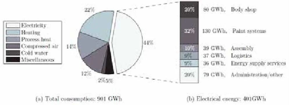
In the manufacturing industry, especially those that use robots for most processes, a significant part of the total energy consumption is accounted for by electrical motors that are used to drive the joints of the industrial robots (Schmidt, Mohammed et al. 2013). As seen in Figure 6 (DaimlerAG 2012), the total energy consumption in Daimler AG Plant Sindelfingen in 2011 was 901 GWh, of which 44% accounted for electrical energy. More specifically it can be noticed that, 20% of the electrical energy is spent in the body shop (where sheet metal is welded into a21
structure), an area known for its high dependability on industrial robots (Meike 2013).
The use of energy efficient industrial robots harbors considerable potential in minimizing the total energy consumption in manufacturing industries. Robot manipulators, in situations which demand high energy-efficiency, are required to fulfill task-based and safety-based application requirements with as little energy consumption as possible. Low static and dynamic power requirements of the actuators should, therefore, be aimed for. Power required in the joints is directly related to the joint velocity and joint torques. Hence, robot design should select and design the mechanical structure by considering high speed ratio and low joint torque requirement; whereas speed ratio is the ratio of robot task speed to the joint speed.
3.4 PERFORMANCE INDICES
“Performance indices are metrics formulated to measure and quantify different performance characteristics of the robot manipulators in its operational workspace” (Patel and Sobh 2014, p. 548). Performance characteristics can be defined as the abilities or traits of the robot manipulator to fullfill the performance requirements (such as those listed in Section 3.3). As noted by (Chang 1988), “A quantitative measure provides us with a rational basis upon which we can, without having to rely on experience and intuition alone, analyze, design, and control the systems” (p. 1). Therefore, performance indices not only facilitate the robot designer to study, evaluate and optimize robot designs and applications, but are also needed to compare different robot manipulator types (such as those listed in Section 3.2) for applicability in a given task or application area (Kim and Desa 1989; Angeles and Park 2008; Patel and Sobh 2014).
Performance indices of robot manipulators have attracted considerable attention from the researcher community, resulting in the introduction of a wide range of performance indices since the mid-1980s. (Klein and Blaho 1987; Tanev and
Figure 6. Total energy consumption in Daimler AG Plant Sindelfingen in 2011 as represented in (Meike 2013, p. 13) based on data given in (DaimlerAG 2012),
22
Stoyanov 2000; Kucuk and Bingul 2006) have conducted literature surveys and have documented, classified and discussed the merits and demerits of various performance indices of robot manipulators. The most recent literature survey in this field was performed by (Patel and Sobh 2014).
3.4.1 Classification of performance indices
Essentially, performance indices listed in the literature can be classified primarily based on their scope. They are categorized as local and global performance indices.
Local performance indices: Local indices are performance metrics that indicate the performance for a specific posture, such as the joint angle combination or the end-point position of the robot manipulator in its workspace. Therefore, the scope of local indices is confined and specifically indicates the local performance characteristic of the robot. Most often these indices are posture-dependent and vary considerably from posture to posture. For example, all the performance indices, which are based on the Jacobian matrix, such as manipulability index (Yoshikawa 1985), condition number (Salisbury and Craig 1982) etc., can be termed as local indices. However, for Cartesian robots these kinematic indices are global.
Global performance indices: In contrast to local indices, global indices are posture- independent. They indicate the performance characteristics of the robot manipulator over the entire workspace. Some of the highly used global indices have been formulated by integrating the values of local indices over the workspace (Gosselin and Angeles 1991; Mansouri and Ouali 2011). Such global indices indicate the overall performance of the robot on an average level (Patel and Sobh 2014); whereas some global indices indicate the minimum or lower bounds of the performance characteristic or the worst case performance for the robot manipulator in its overall workspace (Angeles and López-Cajún 1992; Stocco, Salcudean et al. 2001). Global indices are especially needed for comparing and evaluating different robot manipulator types in order to select the best choice for a given application area.
The relation between local indices and global indices is not straightforward, since high local indices do not always end up in high global indices (Kucuk and Bingul 2005). Hence, designers need to make careful and rational interpretations of the local and global performance indices during the design process. In the interest of brevity, only a few well known performance indices corresponding to each of the performance requirements (listed in 3.3) are reviewed as examples of local and global performance indices.
23
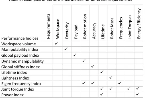
3.4.2 Examples of performance indices
3.4.2.1 Workspace indices:
(Ölvander, Feng et al. 2008) proposed the ‘stroke’ index as a global index of the shape of the workspace. The stroke is defined as the offset between minimum and maximum reach of the end-effector of a robot. On the other hand, the usable workspace volume can be related to a cube inscribed inside the workspace according to (ISO 9283:1998). The so called ISO-cube represents the workspace area where the robot is likely to perform the majority of its tasks. Workspace index, which indicates the total volume of the operational workspace, is often used by designers. One of the many approaches to quantifying the workspace index can be found in (Puglisi, Saltaren et al. 2012).
3.4.2.2 Kinematic manipulability indices:
The kinematic manipulability index is a measure of the ability of the robot to position and reorient the end-effectorin the workspace. The manipulability index proposed by (Yoshikawa 1985) is one of the most widely accepted and used measures for kinematic manipulability. As seen in equation (1), this index (M) is quantified by taking the product of all the singular values () of the Jacobian matrix 𝐽𝐽(𝜃𝜃) . The higher the value of this index, the greater the robot’s manipulability.
𝑀𝑀 = 𝜎𝜎1× 𝜎𝜎2× … 𝜎𝜎𝑚𝑚
𝑥𝑥̇ = 𝐽𝐽(𝜃𝜃)𝜃𝜃̇
Where, 𝑥𝑥̇ and 𝜃𝜃̇ represent the serial manipulators’ end-effector velocity vector and joint velocity vector, respectively. When the manipulability index is close to zero, it indicates that the manipulator approaches singularity, where it can no longer move in at least one direction. The manipulability index is extended to the global level (GMI) by integrating the manipulability index over a grid of points (dw) over the manipulators’ workspace (w); see equation (2). A detailed review of the other commonly used kinematic manipulability indices has been conducted by (Bowling 1998)and (Klein and Blaho 1987).
𝐺𝐺𝑀𝑀𝐺𝐺 =∫ 𝑀𝑀𝑊𝑊 𝑑𝑑𝑑𝑑
∫ 𝑑𝑑𝑑𝑑𝑤𝑤 ⁄
3.4.2.3 Dynamic manipulability indices:
Dynamic manipulability index measures the capabilities of the robot manipulator to accelerate and attain high speeds in the operational space for given input forces/torques in the joint space. The dynamic manipulability index (DMI), defined by (Yoshikawa 1985), is given in equation (3).
𝐷𝐷𝑀𝑀𝐺𝐺 = |𝑑𝑑𝑑𝑑𝑑𝑑 (𝐽𝐽(𝜃𝜃))det (𝑀𝑀) |
(1)
(2)
24
Where M is the inertia matrix of the robot manipulator. However, DMI does not consider the nonlinearities in joint velocity. Performance indices related to the dynamic capabilities of robot manipulators in the operational space have been the subject of a large body of work, (Graettinger and Krogh 1988; Kim and Desa 1989; Bowling and Khatib 2005; Qi, Liwen et al. 2012).
3.4.2.4 Payload indices:
Payload index measures the force transmission capability of the robot manipulator, thereby quantifying the maximum or minimum loads that can be supported on its end-effector. The relation between the input forces/torques in the joints (𝛕𝛕) and the output forces or load (F) at the end-effector for a serial structure is given in equation (4).
𝜏𝜏 = 𝐽𝐽𝑇𝑇𝐹𝐹
JT, represents the transposition of the Jacobian matrix. (Ozaki, Wang et al. 1996)
have proposed the payload index for evaluating robot manipulators. This index, supposes the input force/torque vector (𝛕𝛕) to be unity and uses the Lagrange multiplier 𝛌𝛌P to quantify the maximum and minimum payload capacities (Fmax, FMin)
of the robot manipulator for a given posture. See equation (5). ‖𝐹𝐹𝑀𝑀𝑀𝑀𝑀𝑀‖ = √max (𝜆𝜆𝑃𝑃); ‖𝐹𝐹𝑀𝑀𝑀𝑀𝑀𝑀‖ = √min (𝜆𝜆𝑃𝑃)
The Jacobian matrix is strictly posture-dependent. In order to quantify the maximum (PMax) and minimum (PMin) payload capacity of the manipulator
end-effector within its workspace (W) (Ozaki, Wang et al. 1996) introduced Global payload index as shown in equation (6), which integrates the local payload index as given in equation (5) at a grid of points (dw) over the manipulators’ workspace (w). 𝑃𝑃𝑀𝑀𝑀𝑀𝑀𝑀=∫ ‖𝐹𝐹𝑊𝑊 𝑀𝑀𝑀𝑀𝑀𝑀‖ 𝑑𝑑𝑑𝑑 ∫ 𝑑𝑑𝑑𝑑 𝑊𝑊 ⁄ 𝑃𝑃𝑀𝑀𝑀𝑀𝑀𝑀 =∫ ‖𝐹𝐹𝑊𝑊 𝑀𝑀𝑀𝑀𝑀𝑀‖ 𝑑𝑑𝑑𝑑 ∫ 𝑑𝑑𝑑𝑑 𝑊𝑊 ⁄ 3.4.2.5 Stiffness indices:
Inadequate stiffness in the links and joints of a robot manipulator may cause large end-effector displacements when the external forces and moments are acting on it. These displacements at the end-effector can significantly affect the accuracy, max payload and dynamic characteristics of the robot manipulator. Quantifying the robot manipulator’s stiffness is, therefore, very important while designing robots with high accuracy requirements. The manipulator stiffness matrix (𝐾𝐾𝐶𝐶) is
related to the joint stiffness matrix (𝐾𝐾𝐽𝐽) as represented in equation (7) taken from
(Salisbury 1980). KC= J−1KJJ−T (4) (5) (6) (7)
25
Here, 𝐾𝐾𝐽𝐽 is the joint stiffness matrix, which takes into account the stiffness
properties of the joints (including gears, actuators and servo stiffness) in the joint space and J is the Jacobian matrix. If the stiffness of the arm structures must be included, more complicated methods are needed to calculate the stiffness matrix, for example, by introducing virtual elastic joints along the arms. Many indices, which quantitatively indicate the stiffness performance of the manipulator, have been formulated by using the properties of the stiffness matrix (KC).
Documentation and comparison of various stiffness indices have been performed by (Carbone and Ceccarelli 2010).
A local stiffness index can be directly related to KC by means of various
mathematical operators that can be applied to a matrix such as determinant, trace and norm at a given posture. As an example, the determinant of the stiffness matrix can be used as a local performance index, as seen in equation (8), to investigate the stiffness properties of the manipulator. It is then especially important to study the singularity properties (Carbone and Ceccarelli 2010).
K = Det(KC)
A local index of stiffness performance may not be suitable for design analysis or for evaluation of different robot types. Therefore, designers often formulate global stiffness indices by taking minimum, maximum or mean of the local stiffness index over the manipulator's workspace.
3.4.2.6 Eigen frequency indices:
Although a heavier and rigid link may exhibit better stiffness properties, it could vibrate at a lower frequency due to higher mass in relation to its elasticity combined with the gear elasticity in the joint of the link (De Luca and Book 2008). This behavior can be predicted by the Eigen frequency of the first flexible mode of motion (N1), estimated by equation (9) in the case the joint actuators are locked
by mechanical brakes (Bailey and Ubbard 1985).
N1= √Ki⁄ IE
Where, KI and IE are the localized stiffness values and the effective moment of
inertia values along the actuating axis (i). Effective moment of inertia (IE) of moving
components along the actuating axis (i) is derived based on parallel axis theorem (see equation (10))
IE(i)= ∑ In+ Mnr2 m
n=1
Here, m is the number of moving components which contribute to IE of axis (i), In
and Mn are the mass moment of inertia and mass of the moving component (n)
respectively and rn is the perpendicular distance between the axis along the center
of mass of the moving component (n) and to its parallel axis along the actuating axis (i). It should be noted that r is manipulator posture-dependent, hence, 𝐼𝐼𝐸𝐸(𝑖𝑖)
varies over the workspace and the global index is required to be a function of the local frequencies within the manipulator workspace.
(8)
(10) (9)
26
3.4.2.7 Joint torque indices:
The manipulator dynamic characteristics describe the relation between the input joint torques and the end-effector motion of the manipulator structure (In this thesis, the term ‘input joint torques’ is meant to refer to the actuator forces for prismatic joints and actuator torques for revolute joints unless otherwise indicated). This relationship is represented by the equations of motion in joint space (equation (11)), which is derived by assuming that the manipulator links are rigid and further neglects both the Coulomb friction at the joints and the inertia/gyroscopic effects due to motor rotations (Siciliano, Sciavicco et al. 2009). With the high gear ratios used in industrial robots the gyroscopic effects from the motors can be neglected. However, the behavior of the friction at low speed will have a relatively large influence on available torque and control performance, but this may be handled separately as a nonlinear term in the equations of motion.
𝜏𝜏 = 𝐷𝐷(𝑞𝑞)𝑞𝑞̈ + 𝐶𝐶(𝑞𝑞, 𝑞𝑞̇)𝑞𝑞̇ + 𝑔𝑔(𝑞𝑞)
𝛕𝛕 consists of generalized torques at each joint, whereas (𝑞𝑞, 𝑞𝑞̇, 𝑞𝑞̈) represent the joint positions, velocities and accelerations, respectively. 𝐷𝐷 represents the manipulator inertia matrix, in which off diagonal elements represent inertia coupling between joints, 𝐶𝐶 represents the velocity coupling vector (including both centrifugal and Coriolis terms) and 𝑔𝑔 represents the gravity term. Joint torque index measures the input torques required by the robot manipulator to execute desired end-effector motion at a given posture. Since, in most cases, the inertia matrix is posture- dependent, global torque indices are formulated based on equation (11) in order to perform dynamic analysis and evaluation of robot manipulators based on maximum, minimum or average input torque requirement within its workspace and/or a given operation cycle (Zhao and Gao 2009).
3.4.2.8 Life time indices:
Actuator parts, such as gear boxes, are often associated with most of the breakdown problems in industrial robots. Therefore, the lifetime estimation of the robot gears is considered as one of the indicators for the durability of the robot. The stamina of the gearbox is represented by its rated torque and rated speed. The higher the stamina, the longer the gear life under normal load conditions (Pettersson 2008). Therefore, the lifetime index, as derived by the manufacturer (Nabtesco) for compact gear boxes is related to the rated torque (T0) and rated
speed (N0) of the speed reducer as shown in equation (12).
𝐿𝐿ℎ= 𝐾𝐾 ∙𝑁𝑁𝑁𝑁0 𝑀𝑀∙ (
𝑇𝑇0
𝑇𝑇𝑀𝑀) 10⁄3
Where, Lh is the predicted lifetime in hours and K is a converting factor. Nm is the
average output speed and Tm is the average output torque for the specific robot
cycle.
(12) (11)