Postprint
This is the accepted version of a chapter published in Testing Software and Systems: Lecture
Notes in Computer Science, Volume 8254.
Citation for the original published chapter:
Enoiu, E P., Sundmark, D., Pettersson, P. (2013)
Using Logic Coverage to Improve Testing Function Block Diagrams
In: Testing Software and Systems: Lecture Notes in Computer Science, Volume 8254
(pp. 1-16). Springer Berlin Heidelberg
https://doi.org/10.1007/978-3-642-41707-8_1
N.B. When citing this work, cite the original published chapter.
Permanent link to this version:
Block Diagrams
Eduard Paul Enoiu, Daniel Sundmark, and Paul Pettersson M¨alardalen Real-Time Research Centre (MRTC)
M¨alardalen University V¨aster˚as, Sweden
eduard.paul.enoiu@mdh.se, daniel.sundmark@mdh.se, paul.pettersson@mdh.se
Abstract. In model-driven development, testers are often focusing on functional model-level testing, enabling verification of design models against their specifi-cations. In addition, in safety-critical software development, testers are required to show that tests cover the structure of the implementation. Testing cost and time savings could be achieved if the process of deriving test cases for logic coverage is automated and provided test cases are ready to be executed. The logic cover-age artifacts, i.e., predicates and clauses, are required for different logic covercover-age, e.g., MC/DC. One way of dealing with test case generation for ensuring logic cov-erage is to approach it as a model-checking problem, such that model-checking tools automatically create test cases. We show how logic coverage criteria can be formalized and used by a model-checker to provide test cases for ensuring coverage on safety-critical software described in the Function Block Diagram programming language. Based on our experiments, this approach, supported by a tool chain, is an applicable and useful way of generating test cases for covering Function Block Diagrams.
Keywords: logic coverage, function block diagram, timed automata, model-driven engineering, structural testing
1
Introduction
Within the last decade model-checking has turned out to be a useful technique for gen-eration of test cases from finite-state models [12]. However, the main problem in using model-checking for testing industrial software systems is the potential combinatorial explosion of the state space and its limited application to models used in practice. Safety-critical and real-time software systems implemented in Programmable Logic Controllers (PLCs) are used in many real-world industrial application domains. One of the programming languages defined by the International Electrotechnical Commission (IEC) for PLCs is the Function Block Diagram (FBD). Programs developed in FBD are transformed into program code, which is compiled into machine code automatically by using specific engineering tools provided by PLC vendors. The motivation for using FBD as an implementation model comes from the fact that this language is the standard in many industrial software systems, such as rail transport control.
In this paper, our goal is to help testers automatically develop test cases for safety-critical software systems modeled in FBD that require a certain level of certification.
One example of certification includes logic coverage which needs to be demonstrated on the developed programs. There has been little research on using logic coverage criteria for FBD programs in an industrial setting. One way is that logic coverage is analyzed at the code level [9] while tests are designed at the FBD program level, so time-consuming iterations between levels are required. Even if at the code level, logic coverage is used, it would be difficult to standardize the code generation scheme for different PLC tool vendors in order to map directly the criteria to the original FBD program. Hence, in this model-driven environment it is advantageous to move as much testing activity from code level to FBD program level as possible.
As the first contribution of this paper, we present a framework suitable for trans-forming FBD programs to a formal representation of both its functional and timing be-havior. For this, we implement an automatic model–to–model transformation to timed automata, a well known model introduced by Alur and Dill [2]. The choice of timed automata as the target language is motivated primarily by its formal semantics and tool support for simulation and model-checking. Our goal is not to solve all testing issues (e.g., robustness, schedulability, etc.), but to allow the usage of a framework for for-mal reasoning about logic coverage on FBD programs. The transformation accurately reflects the data-flow characteristics of the FBD language by constructing a complete behavioral model which assumes a read-execute-write program semantics. The trans-lation method consists of four separate steps. The first three steps involve mapping all the interface elements and the existing timing annotations. The latter step produces a formal behavior for every standard component in the FBD program. These steps are in-dependent of timed automata thus are generic in the sense that they could also be used when translating an FBD program to another target language.
As the second contribution, we develop a test case generation technique based on model-checking, tailored for logic coverage of FBD programs. There have been a num-ber of testing techniques used for defining logic coverage using model-checkers, e.g., [7, 19, 20]. However, these techniques are not directly applicable to FBD programs and semantics. We define logic coverage for FBD programs based on the transformed timed automata model. This copes with both functional and timing behavior of an FBD pro-gram. This formal definition is necessary for the approach to be applicable to model-checking. We present how a model-checker can be used to generate test cases for cov-ering an FBD program. Based on our experiments, this method is — for the real world models provided by Bombardier Transportation AB — a useful way of generating test cases for logic coverage both in terms of automation and robustness to changes in the FBD programs as monitored by the model-checker.
The paper is organized as follows. Section 2 briefly overviews PLC software, the IEC 61131-3 standard, timed automata and logic coverage. Section 3 describes our overall testing methodology roadmap. Section 4 introduces the modeling approach for FBD programs and Section 5 shows the transformation scheme into timed automata. Section 6 and Section 7 presents the test case generation method required for logic coverage criteria. Next, we apply our method on a Train Startup Mode example in Section 8. In Section 9 we compare to related work, before concluding in Section 10.
2
Preliminaries
This paper describes how to generate test cases that cover the logical structure of FBD programs, by transforming them to networks of timed automata. In this section, we pro-vide some background details on FBD programs, timed automata and logical coverage.
2.1 FBD Programs and Timer Components
PLCs are widely used in control software from nuclear plants to train systems. A PLC is an integrated embedded system that contains a processor, a memory, and a commu-nication bus. Programs execute in a loop, in which the computation follows the “read-execute-write”semantics. In this way a PLC reads all inputs, executes the computation without interruption, and then writes to its output. FBD, a PLC programming language standardized by IEC 61131-3, is very popular in the industrial practice because of its graphical notations and its data flow nature [18]. Components in an FBD program are the base for a structured and hierarchical application. They are supplied by the man-ufacturer, defined by the user, or predefined in a library. An application generator is utilized to automatically transform each component to a C compliant program with its own thread of execution.
The type of systems we are studying contain a particular type of components named PLC timers. These timers are output instructions that provide the same functions as tim-ing relays and are used to activate or deactivate a device after a preset interval of time. There are two different timer components (i) On-delay Timer (TON) and (ii) Off-delay Timer (TOF). Basically, a timer counts time-based intervals when the input instruction is true or false. In practice many other time configurations can be derived from this ba-sic timers. In order to study how to generate test cases using a model checker for these types of FBD programs we use a formal representation that can cope with timers and timing information.
2.2 Networks of Timed Automata
A timed automaton is a standard finite-state automaton extended with a finite collection of real-valued clocks. The model was introduced by Alur and Dill [2] and has gained in popularity as a suitable model for real-time systems. We give here a brief summary for readers unfamiliar with timed automata theory.
Let C be a finite set of real-valued clocks and B(C) the set of clock constraints, which are finite conjunctions of atomic guards of the form x ./ n, where x ∈ C, n is a natural number, and ./ ∈ {<, ≤, =, ≥, >}.
A timed automaton (A) over actionsA , atomic propositions P and clocks C is a tuple hN, l0, E, I,V i where N is a finite set of control locations, l0is the initial location,
E⊆ N × B(C) ×A ×R1× N is the set of edges. In the case of and edge hl, g, a, r, l0i ∈ E,
we write l−−→ lg,a,r 0where the label g is a guard of the edge, r is the data- or clock reset assignments of the edge, and a is the action of the edge. I : N → B(C) is a function
which for each control location assigns an invariant condition and V : N → 2P is a function which for each control location gives a set of atomic propositions true in the location.
The semantics of A is defined in terms of a state transition system, where the state of A is defined as a pair (l, u), where l is a location and u ∈ RCis a clock assignment in C. A state of A depends on its current location and on the current values of its clocks.
We denote by T (A) all traces σ ofA starting from the initial state (l0, u0) as a
sequence of alternating transitions σ = (l0, u0) a1
−→ (l1, u1) a2
−→ ... an
−→ (ln, un).
A network of timed automata B0k ... k Bn−1 is a parallel composition of n timed
automata over C,A and synchronization functions (i.e., a! is correlative with a?). We refer the reader to [1] for more information on the theory of timed automata.
We consider in this paper model-checking algorithms that perform reachability anal-ysis to check for properties of the form ∃♦ β , with respect to a property β of the lo-cations and the values of the clock. ∃ is the existential quantifier, and♦ is the temporal operator. A reachability property states that there is a path in which β inAis reached. This type of property serves as a basis for formulating various coverage criteria and for deriving properties that could be used by a model-checker to produce test sequences for the timed automatonA.
2.3 Logic-based Coverage Criteria
In this section we briefly describe existing logic-based coverage criteria. In the litera-ture, there are many similar criteria defined, but with different terminology [4]. Also, some definitions of coverage criteria (e.g., MC/DC) have some ambiguities. In order to eliminate the ambiguities and conflicting terminologies, Ammann et al. [5] abstracted logic criteria with a precise definition and formal representation. A predicate is an ex-pression that evaluates to a Boolean value. It consists of one or more clauses. A clause is a predicate that does not contain any logical operators and can be a Boolean variable, non-Boolean variables used for comparison, or a call to a Boolean function.
Clauses and predicates are used to introduce a variety of coverage criteria. This paper presents three different test criteria, each of which requires a different amount of test cases: (1) Predicate Coverage (PC), (2) Clause Coverage (CC), and (3) Corre-lated Active Clause Coverage (CACC). These are defined in the next sections in terms of the FBD program. We note that modified condition/decision coverage (MC/DC) is equivalent to CACC and relies on its original definition [5].
3
Testing Methodology and Proposed Solutions
In this section, we describe our approach to automate test-case generation for FBD programs. Logic coverage criteria are used to define what test cases are needed and we use a model-checker to generate test traces. In addition, the formal framework presented in this paper is tailored for FBD programs, and is composed of the following steps, mirrored in Figure 1:
FBD Program
Timed Automata Model
Logic-based Coverage Criteria
Reachability Properties
UPPAAL model-checker
Test Traces Test Suite
Transformation
2
Annotation Test Generation FB F F F FB PC, CC, RACC …1
∃ ♢ β , ∃ ♢ pi ,∃ ♢ c0and c1...
(Step) (Time) (Inputs) (Outputs) ( 1 ) ( 20s ) (0 1 23) (1 2 3 0)
3
Fig. 1. Testing Methodology Roadmap
1. Model Transformation To test an FBD program we map it to a finite state system suitable for model checking. In order to cope with timing constraints we have cho-sen to map FBD programs to timed automata.
2. Logic Coverage Annotation We annotate the transformed model such that one can formulate a condition describing a single test case. This is a property expressible as a reachability property used in most model checkers.
3. Test Case Generation We now use the model-checker to generate test traces. To provide a good level of practicality to our work we use a specific model-checker called UPPAALwhich is using timed automata as the input modeling language2.
The verification language supports reachability properties. In order to generate test cases for logic coverage of FBD programs using UPPAAL, we make use of UP
-PAAL’s ability to generate test traces witnessing a submitted reachability property [13]. Currently UPPAAL supports three options for diagnostic trace generation: some trace leading to a goal state, the shortest trace with the minimum number of transitions, and fastest trace with the shortest time delay.
While UPPAALis a viable tool for model checking, it is not tailored to test case generation in practice. We demonstrate how to work around this by automatically gen-erating traces for logic coverage of FBD programs described in timed automata and
2The U
how we transform these traces to actual test cases. We discuss these steps in further detail in the following sections. First we start by introducing the FBD programs as a finite syntactical representation to describe its component model nature.
4
Function Block Diagram Component Model
An FBD program is a component model which obeys the read-execute-write seman-tics with a mechanism for monitoring the internal components to determine when the implementation has terminated. Components can be categorized into functions (FUNC) and function blocks (FB). A FUNC does not have any internal state and its output is determined only by the current inputs.
Example 1. An example of an FBD program depicting a Loadshed Contactor Control is shown in Figure 2. Basically the components are equivalent to predicates and in-strumentation points shown in a circuit diagram fashion. The system consists of basic functions (e.g.,AND,OR) and function blocks (e.g.,FAULTEN,RS). In Figure 2,AND is a FUNC. In contrast,FAULTENis an FB because it maintains an internal state and produces outputs based on this state and inputs.
Assume an FBD program defined as the following tuple: FBDProgram, hName, FE, V, P, Coni,
where Name is the program identifier, FE is the set of components defined as the union of FUNC and FB instances, V is the variable set, defined as the union of input (VI) and output (VO) variables, P is the parameter set, defined as the parameters used internally by the program, and Con is the set of connectors between all components (e.g., FB and FUNC). AND RS OR FAULTEN I FLT E BLK FAULTEN 1
Fig. 2. An FBD program showing the graphical nature of the language.
A component in FE has an interface, consisting of a name identifier, input and output ports, and a list of parameters. The interface is used to access the component behavior. When the component is activated the behavior is started using the values read on the in-put ports. When the behavior ends, i.e., when the component implementation terminates
its execution, the output ports are updated. The behavior of a component is typically im-plemented by a code fragment that updates local variables. We define a component as a tuple hName, Port, Bi,where Name is the name identifier, Port is the set ports, defined as the union of input (IP), output ports (OP), and a list of parameters, whereas B is the behavior description of a component.
Recall that in order to express timing constraints within one component, standard PLC timers are used. The timers in a PLC are operated by an internally generated clock that originates in the processor module. Consider the following PLC timer TON defined as a tuple T ON = hT ON1, (IN, PT, ET, Q), Bti, where T ON1 is the name identifier,
IN, PT , ET , and Q are the set of ports and parameters in Port, and Btis the behavior
description. This timer component is an attempt to specify its interface and behavior. From a semantic point of view, FBD programs are a special case of deterministic reac-tive systems. We use more informareac-tive notations to denote the actual behavior. In the following section we present several such notations to describe how FBD programs can be handled by the UPPAALmodel checker.
5
Transforming Function Block Diagrams into Timed Automata
In this section, we introduce the rules that describe the way we transform FBD pro-grams into a network of timed automata, being one step away from test suite generation with the UPPAALtool. Note that the current transformation rules cover one-level hi-erarchy only. The transformation maps to timed automata all the interface elements FE, V, P, and Con alongside the existing timing annotations within the FBD program. These timing annotations are based on the specifications used from structure and be-havioral elements as defined in the FBD language. The transformation process starts by creating a timed automaton for the program description. We place templates of compo-nents and list the composed timed automata network representing the FBD program as FE1k ... k FEn.We consider the target model as a network of timed automata named Timed Au-tomata Component Model (TACM) and defined as a tuple as follows:
TACM, hComp, Pin, Pout, Connections, BTACMi,
where Comp is the set of components that TACM contains, Pinand Poutare the input and
output dataflow ports, respectively, and BTACM is the TACM’s behavior. If Comp = /0 and Connections = /0, then TACM is a primitive component.
The mapping between an FBDProgram and TACM is a function π : FBDProgram → TACM, which maps each component to a TACM primitive component, input variables V Ito the TACM’s component dataflow input ports, output variables V O to the TACM’s component dataflow output ports, connectors to the TACM’s component connections, and the behavioral specification of a component to BTACM. The execution of a
compo-nent is modeled as a timed automaton. The following rules establish in more details BTACMwith regard to the mapping of an FBDProgram to TACM.
An FBD program is executed in a loop and the computation follows the run-to com-pletion semantics. The timed automaton of the FBD program contains a clock variable for modeling a delay between the cycles. A cycle starts when the automaton enters
Waiting
IN==1 && N==2 && counter==0
Running
IN==1 && N==2
IN==1 && N==2 && ET==Pt−counter && counter!=0
IN==0 && N==2 && ET==Pt−counter IN==0 && N==2
ET<=Pt−counter N++, Q=0, counter=Pt Q=0, N++, ET=0 execute? execute? N++, Q=1 Q=0, N++, counter=Pt N++, Q=0, counter−−, ET=0 execute? execute? execute?
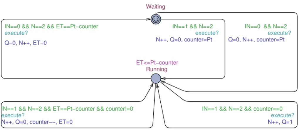
Fig. 3. Timed Automaton of a TON component.
the ReadInputs node and ends in UpdateScanTime node. For a composition TACM the execute operation of each component is extended according to connections and Pin
and Poutvariables. A composition is a set of interconnected components closed under a
specific execution order. The execution order is automatically defined according to the general rules included in the IEC standard. We use the notion of precedence to describe such dependencies on the convention of reading such FBD programs in a top-to-bottom, left-to-right fashion. For each component we assign a precedence priority to the corre-sponding timed automaton. A counter is created in this step to represent the execution priority of a component. In this way we ensure that components are executed one by one. After the last component is evaluated, the counter is reset to repeat the scan cycle. For standard components we assign a timed automaton BTACM with its own
logi-cal execution and no internal concurrency. A component is initially Waiting, and after performing the read action it starts executing until its internal computation is done. Re-consider the PLC timer TON as described in Section 4. A rather straightforward model of the TON component is shown as a timed automaton in Figure 3. The composition interacts with the TON component via execute? action. TON is modeled by a standard time on timer that sets the output Q to true if IN variable is true at least as long as the time PT . In this way, we comply with the standard specification of a PLC timer and the structural definition of the program. The timed automaton encapsulates the internal behavior with both functional and timing properties. This means that when we create a TON model we use a separate instantiation of the behavioral model. Also, every in-stance of TON needs to contain all the variables listed in the interface description and for this reason it is necessary to give each instance of the TON behavioral model a unique identifier.
6
Test Case Generation using the UPPAAL Model-Checker
As a result of the transformation described in Section 5, we consider that the FBD pro-gram is given as a closed network of timed automata as shown in Figure 4. This model
FBD Program [F] Enviroment [E] read? execute? write! Function_FE1 Function_FEn
...
PLC_Cycle_Scan Input_1 Input_n Output...
Fig. 4. Test TA Network for a FBD Program.
contains two sub-networks, one modeling the FBD Program and the other one model-ing its Environment. In addition, we consider a completely unconstrained environment that allows all possible interactions between the timed automata network elements. In this way the cycle scan is used to control the FBD program via read?, execute?, and write! actions.
Let us assume the generic timed automata network of an FBD program together with its PLC cycle scan and environment shown in Figure 4. A trace produced by the model checker for a given reachability property defines the set of actions executed on the FBD program. An example of a diagnostic trace has the following form:
(F0, E0) a1 −→ (F1, E1) a2 −→ ... an −→ (Fn, En),
where (Fk, Ek) are states of the FBD program and PLC cycle scan with environment
constraints, respectively, and akare either internal synchronization actions, time-delays
or read?, execute?, and write! global synchronizations. For FBD programs the se-quence represents only the global synchronizations shown in Figure 4. Test cases are ob-tained by extracting from the diagnostic trace the observable actions read?, execute?, and write!. Obviously a single test case cannot be obtained for every test purpose or criterion. By using a program scan cycle we allow the test suite to be implemented as one or more test sequences separated by resets. To introduce resets in the model, we annotate the PLC cycle scan with a reset transition leading to the initial ReadInputs location. On this transition all variables and parameters (excluding encoded internal variables) are reset to their default value. This reset is hardcoded into the PLC scan cycle for any modeled FBD program in UPPAAL, being an atomic communication be-tween all timed automata.
7
Logic Coverage Criteria for Function Block Diagrams
As mentioned earlier, the basic approach to generating test cases for logic coverage using model-checking is to define a test case as a finite execution trace. If one can char-acterize this execution trace as a temporal logic property to be used, model-checking techniques can be used to produce a test trace for the property. It has also been observed
that criteria such as logic coverage that have constraints involving more than one test trace cannot be handled in this way. Based on TACM description, we propose here to use the logic coverage to annotate the original model and the temporal logic property to be checked with auxiliary data variables and transitions in such way that a set of test traces in the TACM can be used as a test suite in the annotated model. The temporal logic property is described in terms of adding these auxiliary variables and can be used to produce the necessary set of test cases.
In this section we describe what is needed to achieve logic coverage for FBD pro-grams. We envision our logic coverage measurement process where model checking is used to perform more systematic testing. Informally, our approach is based on the idea that to get logic coverage of a specific program it would be enough to (i) find a test trace from the initial state to the end of the FBD program, (ii) annotate the clauses and pred-icates in the FBD program, (iii) formulate a reachability property for logic coverage. In addition, the values of the clauses and predicates are remembered in every program execution with the outcome of the trace being different. To apply the criteria, necessary properties for the integration of logic coverage need to be fulfilled.
Program Reset: The FBD program is assumed to have an implicit control loop, so the reset can occur in the program without modifying in any way the transformed timed automata. We consider that TACM has a special reset transition that restores the pro-gram to its initial state and the propro-gram cycle enters the ReadInputs node. Clearly, multiple execution traces of the FBD program are mapped to a single execution trace containing sub-traces separated by resets. An example of a single execution trace for an FBD program has the following form:
(F0, E0) read −−→ (F1, E1) execute −−−−→ (F2, E2) write −−−→ (F3, E3) read −−→ (F4, E4) execute −−−−→ (F5, E5) write −−−→ .
The test trace3indicates that the checked reachability property is satisfied. This
partic-ular trace contains two-sub traces, each finishing with the write actions.
Component Annotation: Predicates in an FBD program are components that can be evaluated to a boolean value, i.e., true or false. Predicates can be identified from the instrumentation points in the FBD program. Let P be a set of predicates in an FBD program and C be the set of clauses in P. For each predicate p ∈ P, let Cpbe the set of
clauses in p. C is the union of the clauses in each predicate in P. The following coverage criteria are defined as follows:
– PC: For each p corresponding to a component in the FBD program, a test suite contains two requirements: p evaluates to true, and p evaluates to false.
– CC: For each c corresponding to a component in the FBD program, a test suite contains two requirements: c evaluates to true, and c evaluates to false.
3The states are shown in this trace where (F
k, Ek) are states of the FBD program and PLC cycle scan with environment constraints, respectively, and the global actions are read, execute, and write.
– CACC: For each p ∈ P and each clause ci∈ Cp, a test suite contains two
require-ments: cievaluates to true and false so that it solely determines p.
For PC a solution is to analyze every predicate in the FBD program. PC indicates that each component in the FBD program has taken every outcome at least once. This mech-anism is implemented by specifying a set of predicate parameters. We annotate every BTACM with an auxiliary boolean variable vi for each predicate p to be covered. For
every edge in a component with destination waiting : l−−→ waiting, vg,a,r iis added to r
as-signment. In addition, for CC the annotation of clauses ciis done based on the evaluated
components. A test trace achieves full CC when it causes each input and parameters of all components to be true at least once during model checking. Similarly for CACC we store the values of p and ci: and pass the information as a pair (p, ci). We refer to these
value combinations which are needed for logic coverage criteria as test goals.
Reachability Property Annotation: For using the test generation capability of a model-checker, the test property must be formulated as a reachability property and checked by the timed automata. Hessel et al. [14] already proposed a way to apply coverage criteria to specifications described in timed automata. In addition, we propose the usage of logic coverage directly on implementation models. The reachability property for full PC will require that for all p to be exercised:
∃ ♦ (v0== 1 and v1== 1 ... and vk== 1).
For generating test traces for CC we check whether the auxiliary variables are cov-ered for each ci in the program similarly to the reachability property for full PC. In
addition, to achieve CACC for a component in the FBD program, we would need to define a reachability property that leads to a goal set satisfying CACC for every ciin p.
What remains is to calculate the total desired set of combinations for each component in an FBD program.
8
Example: Train Startup Mode
In the previous section we presented a technique to compute logic coverage for FBD programs. In the following we show empirically that the performance of our technique is sufficient for practically relevant examples. We have applied our method on a real world example provided by Bombardier Transportation AB. We present here how our method is applied to test a part of the MITRAC Train Control and Management Sys-tem(TCMS) provided within the ATAC research project. TCMS is a distributed system, built on open standard IP-technology that allows easy integration of control and commu-nication functions for high speed trains. We are concerned with both the transformation of FBD programs to timed automata models and the time and memory used to generate test cases. The tools used for developing these programs are based on the MULTIPROG software. The FBD program is transformed using the MOS tool4[10].
4MOS is a tool for model-based and search-based testing of safety-critical systems implemented in FBD language, developed at M¨alardalen University since 2012.
8.1 Experiments
The experiments reported here are based on an example program, part of TCMS. We use an FBD program of a train Startup Mode System (TSM) and generate test cases for logic coverage. In the process, we describe the FBD program, the program to timed automata model transformation and the annotations made to the model.
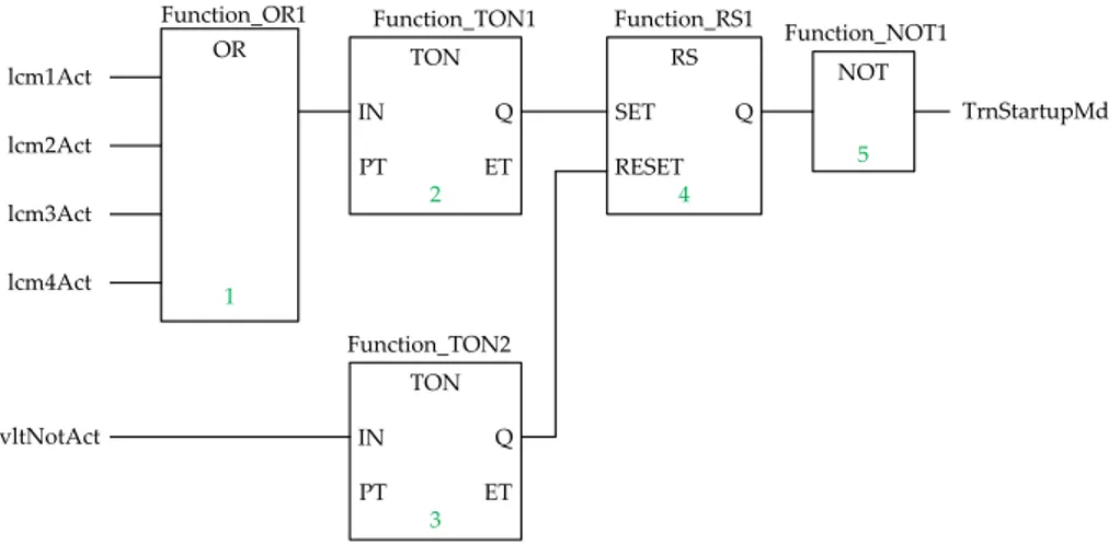
TON IN Q PT ET 2 Function_TON1 OR 1 Function_OR1 TON IN Q PT ET 3 Function_TON2 RS SET Q RESET 4 Function_RS1 NOT 5 Function_NOT1 lcm1Act lcm2Act lcm3Act lcm4Act vltNotAct TrnStartupMd
Fig. 5. Simplified Train Startup Mode modeled as an FBD program.
The train is built up using motorized cars and intermediate trailer cars with pan-tographs. These cars are combined to create a fixed 8-cars train set, each with its own complete system for control and propulsion. The task of the train operating in the startup mode is imposed by the controller FBD program depicted in Figure 5. When the first Line Converter Module (LCM) is active, the propulsion unit becomes active, i.e. any of the four inputs becomes true. When activating the propulsion system, the program waits an additional five seconds and then sets the output to false, which means that the train is not in the startup mode anymore. If the NotAct is true for at least five seconds, the element is reset and the output is set true as in the startup mode.
To validate our approach for generating test cases for logic coverage, we imple-mented our method in our previously developed MOS tool for analyzing and executing FBD programs. The TSM system is transformed automatically in the fully formal and executable timed automata used by UPPAAL. The TSM system is modeled as a par-allel composition of several processes. Several boolean and integer variables are used for recording information: read!, execute! and write! synchronization channels are used to model the execution of the FBD program, et is used to keep track of the elapsed time in timer components, lcm1act, lcm2act, lcm3act, lcm4act for recording the input variables generated by the LCM input automaton, notact for representing the line voltage activation, TrnStartupMd for recording the startup mode of the train, piand cifor recording each covered item, and pt for recording the delay from the first
UPPAALmodel checker for generation of test suites for logic coverage by reachability analysis.
Table 1 shows the generation time (in seconds) for test suites generated from dif-ferent logic coverage criteria of the TSM example, and the length (number of program cycles) of the generated test suite. We notice that for CACC test cases result in longer traces than for PC and CC. The generation time for CACC is slightly higher than the number for PC and CC. However, the number of program cycles is twice as high be-cause CACC is combining already generated test suites for PC and CC.
Table 1. Generation time and test suite length for various coverage criteria Coverage Criterion Generation Time (seconds) Test Suite Length (program cycles)
PC 18,04 14
CC 18,21 14
CACC 22,86 25
8.2 Logic Coverage and Timing Components
One of the objectives for this experiment is to assess the applicability and scalability of using logic coverage for testing FBD programs with various sizes and complexities. An expected characteristic of the FBD program is its associated timing behavior. For the TSM model, the TON automaton appears to be significantly affecting the generation time. Therefore, we focus the discussion on timer components (e.g., TON, TOF, etc.) because these cases lead to a bigger search space. We modify the program by increasing or decreasing the number of TON components in the TSM model. We observed that an FBD program consisting of ten or more TON components are difficult to cover. This is not surprising as the timing components are varying the timing of the entire model and therefore the number of predicates and clauses in the program. The programming of two or more timers components together in the same FBD program is called cascading. From our experiments with timer components in TCMS (over 300 FBD programs), the number of TON and TOF components is always lower than five. Nevertheless we were interested to show that —for the studied program— our method of generating test cases for covering FBD programs is applicable and scalable.
The results, listed in Table 2, show that the memory usage increase essentially lin-early with the number of timing elements. If we compare test suite length with the generation time, it can be seen that is much cheaper to compute FBD programs for FBDs with less than ten timer components than computing for fifty timer components. We can try to explain this behavior in the sense that timer components pose restrictions on the solution because it contains more possible behaviors. Thus, searching through more timer components takes longer. We note that the use of timer elements restricts the handling of larger systems, with an increased cost of generation time and used memory.
Table 2. Results of obtaining PC of the TSM example with increasing timer elements Timers Generation Time (seconds) Test Suite Length (program cycles) Memory Usage (MB)
0 0,62 4 15 1 1,54 5 27 2 3,29 7 61 5 6,38 14 122 10 6,79 18 200 50 31 36 520
9
Related Work
Previous contributions in testing of FBD programs range from a simulation-based ap-proach [21] to verification of the actual FBD program code [6, 16]. The technique in [6] is based on Petri Nets models. In comparison to our work, they are not coping with the internal structure of the PLC logical and timing aspects. It is our opinion that test-ing FBD programs can be complemented by ustest-ing a model-checker as presented in this paper. Similar to this work, Rayadurgam and Heimdahl [20] have defined a com-plete formal framework that can be used for coverage based test-case generation using a model checker. For a detailed overview of testing with model checkers we refer the reader to Fraser et al. [12].
A model checker has been used to find test cases to various criteria and from pro-grams in a variety of formal languages [7, 15]. In addition, Black et al. [3] discuss the problems encountered in using a model-checker for test case generation for full-predicate coverage and explain why logic coverage criteria is not directly applicable for model-checking. Rayadurgam et al. [19] present an alternative method that mod-ifies instead the system model and are obtaining MC/DC adequate test cases using a model-checking approach. Similarly to our work, the system model is annotated and the properties to be checked are expressible as a single test sequence. However, this technique is not coping with the timing behavior of an FBD program as we do and only MC/DC criteria is investigated. We provide an approach to generate test cases for different logic criteria (e.g., PC, CC, and CACC) that are directly applicable to FBD programs.
The idea of using model-checkers for verifying and testing FBD programs is not new [22, 8]. These two approaches use the UPPAALmodel checker and UPPAALTRON for verification of FBD programs, however they translate their model for functional ver-ification. Soliman et al. [22] provide an automatic transformation to timed automata and their verification methodology is used to check the model against safety requirements. In contrast to the online model-based testing approach used in [8] we generate test suites for offline execution.
Related to this work but outside the PLC testing community, the most notable ef-forts have been focusing on test coverage for data flow languages. For example, for the Lustre language there are contributions [17] describing an activation condition concept that can be used when data flows from an input edge to an output edge. While this approach studied the effect of structural coverage criteria on the overall program, we
study the ability to generate test cases and its effect on the test artifacts, i.e., predicates and clauses, tailored for FBD programs.
To our knowledge, not much theoretical and experimental data is available regard-ing the usage of logical coverage for Function Block Diagrams. In our previous work [11] we have defined a model-based test generation method tailored for Function Block Diagram programs and demonstrated how to use the UPPAALtool for model check-ing the implementation in order to ensure compliance to quality requirements includcheck-ing unit testing. As a consequence of these results we have developed our own tool chain called MOS [10] to support both a model and search-based testing approach which can include specific coverage measurements. The criteria in this paper is based on our pre-vious work and is an attempt to automatically compute logic coverage using a model checker for Function Block Diagrams.
10
Conclusion
In this paper we have shown how test case generation for ensuring logic coverage on Function Block Diagrams can be solved as a checking problem, such that model-checking tools are automatically creating traces which can be transformed to test cases. We show how logic coverage criteria can be formalized and used by a model-checker to provide test cases. The results show that model checking scales well for handing logic coverage and we suggest a general approach for handling tests to cover the structure of the implementation model. The method is supported by a tool chain that can be used to produce relevant test cases. We are currently investigating this approach on a larger case study. In addition, we want to extend the evaluation to measure both efficiency and effectiveness of our approach.
Acknowledgments
The authors would like to thank Elaine Weyuker and Thomas Ostrand for their valu-able comments on this work. This research was supported by VINNOVA, the Swedish Governmental Agency for Innovation Systems within the ATAC project.
References
1. R. Alur. Timed Automata. In Computer Aided Verification, pages 688–688. Springer, 1999. 2. R. Alur and D. Dill. Automata for Modeling Real-time Systems. Automata, languages and
programming, pages 322–335, 1990.
3. Paul Ammann, Paul E Black, and Wei Ding. Model Checkers in Software Testing. In NIST-IR 6777, National Institute of Standards and Technology Report, 2002.
4. Paul Ammann and Jeff Offutt. Introduction to Software Testing. In Cambridge University Press.
5. Paul Ammann, Jeff Offutt, and Hong Huang. Coverage Criteria for Logical Expressions. In 14th International Symposium on Software Reliability Engineering, pages 99–107. IEEE, 2003.
6. L. Baresi, M. Mauri, A. Monti, and M. Pezze. PLCTools: Design, Formal Validation, and Code Generation for Programmable Controllers. In IEEE International Conference on Sys-tems, Man, and Cybernetics, volume 4, pages 2437–2442. IEEE, 2000.
7. Paul Black. Modeling and Marshaling: Making Tests from Model Checker Counter-examples. In Proceedings of the 19th Digital Avionics Systems Conference, volume 1, pages 1B3–1. IEEE, 2000.
8. L.D. da Silva, L.P. de Assis Barbosa, K. Gorgˆonio, A. Perkusich, and A.M.N. Lima. On the Automatic Generation of Timed Automata Models from Function Block Diagrams for Safety Instrumented Systems. In 34th Annual Conference of IEEE Industrial Electronics, pages 291–296. IEEE, 2008.
9. Kivanc Doganay, Markus Bohlin, and Ola Sellin. Search Based Testing of Embedded Sys-tems Implemented in IEC 61131-3: An Industrial Case Study. In International Conference on Software Testing, Verification and Validation Workshops. IEEE, March 2013.
10. Eduard Paul Enoiu, Kivanc Doganay, Markus Bohlin, Daniel Sundmark, and Paul Petters-son. MOS: An Integrated Model-based and Search-based Testing Tool for Function Block Diagrams. In International Conference on Software Engineering Workshops. IEEE, May 2013.
11. Eduard Paul Enoiu, Daniel Sundmark, and Paul Pettersson. Model-based Test Suite Gen-eration for Function Block Diagrams using the UPPAAL Model Checker. In International Conference on Software Testing, Verification and Validation Workshops. IEEE, April 2013. 12. Gordon Fraser, Franz Wotawa, and Paul E Ammann. Testing with Model Checkers: a
Sur-vey. In Journal on Software Testing, Verification and Reliability, volume 19, pages 215–261. Wiley Online Library, 2009.
13. A. Hessel, K. Larsen, M. Mikucionis, B. Nielsen, P. Pettersson, and A. Skou. Testing Real-time Systems using UPPAAL. Formal Methods and Testing, pages 77–117, 2008.
14. Anders Hessel, Kim Larsen, Brian Nielsen, Paul Pettersson, and Arne Skou. Time-Optimal Real-Time Test Case Generation Using UPPAAL. In Lecture Notes in Computer Science, Formal Approaches to Software Testing, pages 114–130. Springer Berlin Heidelberg, 2004. 15. Hyoung Seok Hong, Insup Lee, Oleg Sokolsky, and Hasan Ural. A Temporal Logic-Based
Theory of Test Coverage and Generation. In Tools and Algorithms for the Construction and Analysis of Systems, pages 327–341. Springer, 2002.
16. E. Jee, S. Kim, S. Cha, and I. Lee. Automated Test Coverage Measurement for Reactor Pro-tection System Software Implemented in Function Block Diagram. In Journal on Computer Safety, Reliability, and Security, pages 223–236. Springer, 2010.
17. A. Lakehal and I. Parissis. Lustructu: A Tool for the Automatic Coverage Assessment of Lustre Programs. In International Symposium on Software Reliability Engineering, pages 10–pp. IEEE, 2005.
18. M. ¨Ohman, S. Johansson, and K.E. ˚Arz´en. Implementation Aspects of the PLC standard IEC 1131-3. In Journal on Control Engineering Practice, volume 6, pages 547–555. Elsevier, 1998.
19. S Rayadurgam and MPE Heimdahl. Generating MC/DC Adequate Test Sequences Through Model Checking. In NASA Goddard Software Engineering Workshop Proceedings, pages 91–96. IEEE, 2003.
20. Sanjai Rayadurgam and Mats PE Heimdahl. Coverage Based Test-Case Generation using Model Checkers. In International Conference and Workshop on the Engineering of Com-puter Based Systems, pages 83–91. IEEE, 2001.
21. S. Richter and J.U. Wittig. Verification and Validation Process for Safety IC Systems. In Nuclear Plant Journal, volume 21, pages 36–36. EQES, Inc., 2003.
22. D. Soliman, K. Thramboulidis, and G. Frey. Function Block Diagram to UPPAAL Timed Automata Transformation Based on Formal Models. Information Control Problems in Man-ufacturing, 14(1):1653–1659, 2012.