Scienpress Ltd, 2015
Mystery of Mosul Dam the most Dangerous Dam in the
World: Foundation Treatment during Construction
Nasrat Adamo1, Nadhir Al-Ansari2, Issa E. Issa3, Varoujan Sissakian4 and Sven Knutsson5
Abstract
Mosul dam was constructed on the beds of Fatha Formation (Middle Miocene). The beds of the formation are about 250 m thick composed of Marls, chalky limestone; gypsum, anhydrite, and limestone form a layered sequence. They are highly karstified. As a consequence, plenty of grouting operations were carried out to fill all the cavities, fractures, joints and to stop the seepage under the foundation of the dam. The main grouting operations were Blanket grouting and deep grout curtain. It was necessary to perform an extensive maintenance program to control the seepage process within the grouted zone to stop dissolution of gypsum and protect the safety of the dam.
Keywords: Mosul Dam, Grouting, Karstification, Sinkholes
1 Introduction
In solving the seepage problems expected in any new dam, foundation treatment plays a great role in preserving its safety and integrity. In Mosul dam this takes even greater and more important function. This is attributed to the complexity of the geology and the presence of soluble gypsum and anhydrite in the form of primary gypsum/anhydrite in thick layers and also as secondary gypsum/anhydrite present in joints or mixed with fine clays in whole gypsum breccias layers. In addition to the existence of weathered layers of limestone which are characterized by a lot of cracks, fissures, joints and cavities which make them very pervious and erodible.
Grouting in gypsiferous formations is a very tricky operation. Because when such operation begins to seal some seepage paths, this will result in an increase of hydraulic gradient locally in others. James and Kirkpatrick [1] explained that water passing over gypsum becomes chemically saturated within a flow path and in this zone of saturation no further
1Consultant Engineer, Sweden.
2,3,5Dept. of Civil, Environmental and Natural Resources Eng., Luleå University of Technology. 4Consultant Geologist.
dissolution occurs. As flow continuous, the zone moves downstream and eventually passes from the exit. At this stage, dissolution rates accelerate again sharply. Results of studies of Morrison-Knudsen Engineers Inc.[2] also confirmed James and Kirkpatrick comments regarding sensitivity of gypsum solubility to hydraulic gradient and flow. Their report indicates that for seepage velocities of 10-4 cm/sec in a 2 cm wide gypsum vein should
dissolve at a rate of few centimeters per year from an advancing front. If the velocities were about 10-2 cm/sec. the gypsum could dissolve at a rate of 9 meter per year. Dissolution
occurs until seepage water reaches a calcium saturation of 2000 ppm. Hence the dissolution zone moves downstream as greater quantities of unsaturated water attack a gypsum vein. From Soviet experience gained by soviet engineers from the design and construction of dams in eastern Siberia and central Asia on gypsiferous foundations it is permissible to build such dams provided that these gypsiferous rock structures are with permeability of not more than 0.1 m/day (4x10⁻⁴ cm /sec) [3]. The same authors cited also the case of the
Kama dam on the river Kama in which the upper part of its foundation to a depth of 50 m is composed of hard and soft rocks represented by sandstones, argillites, limestone, dolomites, and marls, and the lower part by sulfate complex in the form of beds of compact gypsum and anhydrite with a thickness up to 120 m. The dam was successfully built with protection measures against seepage and piping consisting of an upstream clay blanket of 100 meter length, and a deep grout curtain connected to the blanket at the upstream and a drainage system to localize seepage flow. This arrangement provided reliable operation of the structure for 30 years after which it became necessary to conduct works on strengthening and maintaining the grout curtain
From all these it seems it is most difficult to seal a cracked or fissured gypsum formation permanently, especially in the presence of other formations which are also jointed, cracked and are highly conductive to flow as in Mosul dam foundations and in the view of the very high heads created by the reservoir.
Nevertheless, the designers of the dam considered that grouting should be used as the anti- seepage element for the deep cutoff under the dam, while construction of positive cutoff in the form of concert diaphragm could have been used instead. Hydrofraise machines for the construction of such diaphragm to a depth of 100-120 m from the river bed level were at use at that time in the world.
2 Grouting Works Details
The treatment of the Mosul dam foundations consists of two main elements: a) Blanket grouting.
b) Deep grout curtain.
2.1 Blanket Grouting
This was performed under the core of the main dam. It was intended to close the openings originally existing in the foundation rocks, creating thereby a more homogenous upper part of the foundation with respect to the permeability and compressibility. The blanket grouting should also create a bulk head at the top of the grout curtain and should elongate the seepage lines, in addition to closing any preferential path of seepage at the contact of the core with the foundations. Permeability tests were conducted using Lugeon test in
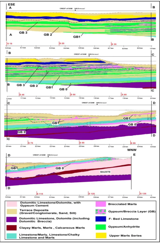
exploratory holes before starting grouting operation to find out later the efficiency of completed work. High permeability zones were found with average values of 28.7 Lu on the right bank from Sec. 87 to Sec. 113 and on left bank an average value of 54.5 Lu from Sec. 64 to Sec.86 (Fig. 1).
The lugeon test, sometimes called also Packer test, is an in-situ testing method widely used to estimate the average hydraulic conductivity of mass rock and the results provide information about horizontal conductivity of the rock mass including the rock matrix and the discontinuities. The test is named after [4], a Swiss geologist who first formulated the test. For details and description of procedure consult [5,6,7,8].
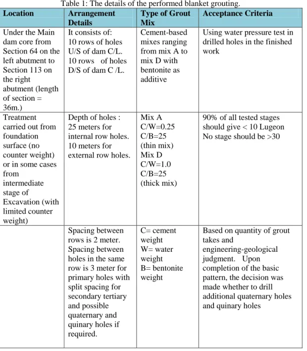
The details of the performed blanket grouting are given in table (1). Final evaluation of the quality of the completed grouting after finishing the basic pattern (P, S, T) holes and even after performing quaternary and quinary holes showed that some sections of the blanket did not meet the acceptance criteria. These were mainly in Sec. 115 and Sec. 110 on the right side with residual permeability of 24.1 Lu and 20.8 Lu respectively in chalky limestone beds and in Sec. 65 and Sec. 69 on left bank with permabilities of 11.6 Lu and 11.7 Lu in the transition zone of gypsum/breccias layers GB3 and GB2 (see Fig. 1) and very likely in limestone bed intercalated in clayey series. These results show the possibility of some deterioration of the blanket at these locations in the future.
2.2 Deep Grout Curtain
It is meant to create a barrier against seepage flow in the foundations under the dam and reduce the permeability of the grouted zones to the possible minimum values. This is intended to hinder or even stop the dissolution of gypsum and anhydride layers in primary form and secondary gypsum in joints, fissures or cavities in other erodible layers. It was also meant to plug joints, cracks, fissures, and fill the present cavities in the limestone in the F-beds and in the chalky series reducing the general seepage flow in the foundation and reduce any erosion process in these rocks.
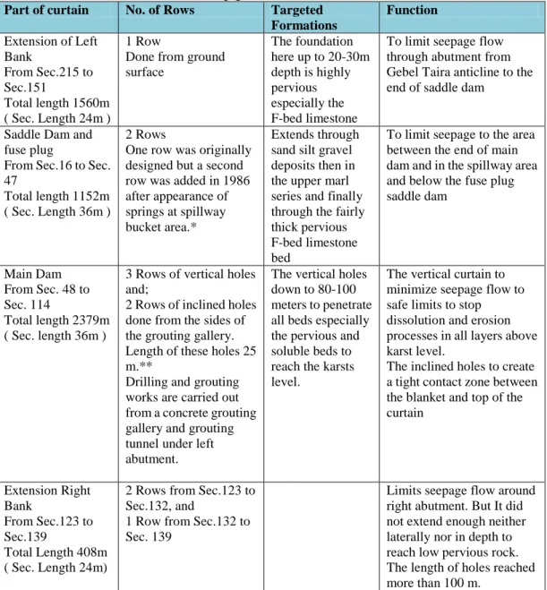
It is very clear from the extensive geological drilling performed during the investigation phase that the geology along the dam axis has been subjected to much tectonic movements and disturbances, in addition to effects of weathering. All these factors required that the grout curtain should adapt to the variable geology along the axis and also to the variation of water head along this axis. Based on this the curtain is divided in to four parts, namely; 1) the extension of left bank, 2)the Saddle dam and fuse plug ,3)the deep grout curtain under the main dam and 4) the extension at the right bank. All these parts were carried out from the ground surface except the part under the main dam (Valley floor and abutments) which was performed from the concrete grouting gallery and its extension tunnel at the left abutment, while grouting under the spillway head work was performed from the gallery in the lower part of this structure. Table 2, describes the main features of these parts including the extent of each, the targeted formations and the specific goal intended to be achieved. The construction of the curtain under the main dam was done from a concrete gallery extending from the right bank to the left bank. It was built in open cut at the bottom of the cut off trench of the dam and it is provided with an access tunnel leading to the left bank ground surface and another access from the right bank. The gallery itself continues in the left direction as a grouting tunnel which leads to the gallery under the spillway head work. Pairs of peizometers u/s and d/s of the curtain were installed in the gallery to monitor the performance of the grout curtain during operation and they proved to be very useful in the stage of maintenance grouting to locate deteriorating areas.
The depth of the curtain along the dam axis had to be decided by drilling a deep exploratory hole in each section with 100% core recovery and carry out a water pressure test to check the permeability of each of the layers encountered and correlating the results with the type of rock and the quality of the retrieved rock cores. Reduction of permeability to safe limit within the treated depths should be the end result of the grouting operations.
The accepted limits of residual permeability were set as in table 3. Table 1: The details of the performed blanket grouting.
Location Arrangement Details
Type of Grout Mix
Acceptance Criteria
Under the Main dam core from Section 64 on the left abutment to Section 113 on the right abutment (length of section = 36m.) It consists of: - 10 rows of holes U/S of dam C/L. - 10 rows of holes D/S of dam C /L. Cement-based mixes ranging from mix A to mix D with bentonite as additive
Using water pressure test in drilled holes in the finished work
Treatment carried out from foundation surface (no counter weight) or in some cases from intermediate stage of Excavation (with limited counter weight) Depth of holes : - 25 meters for
internal row holes. - 10 meters for
external row holes.
Mix A C/W=0.25 C/B=25 (thin mix) Mix D C/W=1.0 C/B=25 (thick mix)
- 90% of all tested stages should give < 10 Lugeon - No stage should be >30
Spacing between rows is 2 meter. Spacing between holes in the same row is 3 meter for primary holes with split spacing for secondary tertiary and possible quaternary and quinary holes if required. C= cement weight W= water weight B= bentonite weight
Based on quantity of grout takes and
engineering-geological judgment. Upon completion of the basic pattern, the decision was made whether to drill additional quaternary holes and quinary holes
Table 2: Parts of the Deep grout Curtain and their Characteristics.
Part of curtain No. of Rows Targeted
Formations Function Extension of Left Bank From Sec.215 to Sec.151 Total length 1560m ( Sec. Length 24m ) 1 Row
Done from ground surface The foundation here up to 20-30m depth is highly pervious especially the F-bed limestone
To limit seepage flow through abutment from Gebel Taira anticline to the end of saddle dam
Saddle Dam and fuse plug
From Sec.16 to Sec. 47
Total length 1152m ( Sec. Length 36m )
2 Rows
One row was originally designed but a second row was added in 1986 after appearance of springs at spillway bucket area.*
Extends through sand silt gravel deposits then in the upper marl series and finally through the fairly thick pervious F-bed limestone bed
To limit seepage to the area between the end of main dam and in the spillway area and below the fuse plug saddle dam Main Dam From Sec. 48 to Sec. 114 Total length 2379m ( Sec. length 36m )
3 Rows of vertical holes and;
2 Rows of inclined holes done from the sides of the grouting gallery. Length of these holes 25 m.**
Drilling and grouting works are carried out from a concrete grouting gallery and grouting tunnel under left abutment.
The vertical holes down to 80-100 meters to penetrate all beds especially the pervious and soluble beds to reach the karsts level.
The vertical curtain to minimize seepage flow to safe limits to stop dissolution and erosion processes in all layers above karst level. The inclined holes to create a tight contact zone between the blanket and top of the curtain Extension Right Bank From Sec.123 to Sec.139 Total Length 408m ( Sec. Length 24m)
2 Rows from Sec.123 to Sec.132, and
1 Row from Sec.132 to Sec. 139
Limits seepage flow around right abutment. But It did not extend enough neither laterally nor in depth to reach low pervious rock. The length of holes reached more than 100 m.
*These springs appeared in February 1986 at the filling of the reservoir for the first time
and resulted from the seepage under the dam and passing under the spillway foundation and threatened its stability. Therefore it was necessary to strengthen the curtain here.
** The inclined holes were meant to improve contact between the blanket grouting and the
Table 3: The accepted limits of residual permeability.
Extension Left Saddle Dam and Fuse Plug
Main Dam Extension Right
No specific Lugeon
value required Acceptability is
judged from the quantities of grout take and types of foundation rocks 90% of all stages < 5 Lu 100% of all stages < 10 Lu Upper 30 m 95% of all stages < 2Lu 100% of all stages < 5Lu Below 30 m 95% of all stages < 5 Lu 100% of all stages < 10 Lu No specific Lugeon value required. Acceptability is judged from the quantities of grout take and types of foundation rocks
2.2.1 Main Dam Curtain
Full picture of permeability variation under the dam and along its’ axis was made by carrying out the usual water pressure tests in the drilled exploratory holes as a first step. This variation is shown in table 4 at the various formations from lower to upper units.
Table 4: Variation of Permeability in Various formations under the main dam.
High Permeability Moderate to low Permeability
Low to Nil Permeability
In Dolomitc limestone above the well-defined karst level*
In formations such as clayey series, GB layers as fossil karst and upper marl series above karst level
All formations below Karst level
In GB0 on the right bank In chalky series in valley floor and right bank(Sec.78 to Sec.114 ) above karst level In GB3 layer and In transition zones above karst level In Isolated Limestone intercalated in clayey series above karst level
In F-bed limestone in left bank above karst level
*for karst level definition refer to [9].
After completing the basic grouting pattern with (P, S, T) holes the need arose for adding quaternary and quinary holes. Residual permeability values in many of these areas remained above the acceptance criteria .These locations were called “Windows “ and were located in the following parts of the curtain as follows:-
-Large areas in chalky series from Sec. 79 to Sec. 92, and Sec. 97, 102, 104, 106 and Sec.108.
-Large areas above the grouting tunnel between Sec. 57 and Sec. 61 as well as limited areas in Sec. 55 and fairly large area below the spillway head structure, Sec. 49 to beginning of Sec. 54.
Since the end of grouting activates several of these zones were treated again by additional holes (Maintenance grouting) and this work continues even up till today. The grouting mixes used were basically (Cement Bentonite mixes) but bentonite gel mix and silica gel mix were also used in quaternary and additional quinary holes when the basic pattern continued to show high residual permeability.
At later stage (November 1987) Massive mix was used when some of the completed areas were showing deterioration and high grout takes were required and in a very short time [10]. This mix consisted of two weight of sand and one weight of cement plus 4% bentonite. The need to deliver large volumes of this mix in relatively short time required drilling one service hole from the top of the dam to the gallery and encasing it with 15cm steel pipe. Grout mix was delivered to the intake by trucks and pumped through the pipe and it was possible to grout in more than one location in the gallery at the same time. This method proved to be very useful in emergency situations and also during the maintenance work up to now as indicated by the Mosul Dam International Board of Experts [11]. Two more such delivery pipes were installed later on at other sections.
2.2.2 Saddle Dam and Fuse Plug Curtain
Exploratory holes with 100% core recovery and water pressure tests were also completed to define the depth of curtain. High permeability zones were located in the F-bed limestone and in the under laying anhydride / gypsum breccias GB3. After completion of the two row curtain, limited zones had residual permeability higher than the accepted design criteria. These were located between Sec.31 and Sec. 35 in addition to Sec.38.Two areas where in F- bed while three other areas in GB3. Cement base grouts were used in the basic (P, S, T) pattern and bentonite gel mix was used in the quaternary and quinary holes which were drilled after recording high takes in the basic (P ,S ,T) pattern.
2.2.3 Left Extension Curtain
The one row curtain at this part extended over a distance of 1500m. It was meant to treat highly pervious F-bed limestone formation. Only 12 exploratory holes were drilled to depths between 59m to 120m. Full core recovery was performed with water pressure tests to define approximately the limit between pervious and impervious rocks. This indicated the presence of high permeability areas in the F- bed limestone .On the contrary the GB3 and the upper marl series showed very low permeability.
After completion of the grouting holes using cement base grout only no check holes were performed. But quantity of grout consumed was used as indicators of the efficiency of treatment. High consumption were recorded in Primary and Secondary holes and in many Tertiary holes between Sec. 201 to Sec. 198, moderate takes to low takes from Sec. 197 to Sec. 189. In sections 182,180 and 178 grout takes were so high that quaternary holes and quinary holes were also performed.
2.2.4 Right Extension
This extension extends from end of the dam at right bank Sec.123 for a length of 408 to Sec.139. It consists of two row curtain from Sec. 123 to Sec. 133 and one row curtain from Sec. 134 to Sec. 139.
Exploratory drill holes were performed with full core recovery and water pressure tests to define the line between pervious and impervious rocks. The depth of the upstream row in the two row curtain varied from 135m to 125m, while the second row depth varied from 90 m to 60 m. The direction of the extension follows slightly towards upstream. The length and direction were selected as a result of hydro geological study based on a mathematical model [12] and also by using the water pressure tests. Parent rock permeability results had showed very high permeability values in the dolomitic limestone above and below the karts level which remains very deep and runs in a perpendicular direction to the extension. No check holes were drilled after the completion of this extension but examination of the grout consumed quantities showed average value range between 295 kg/m at Sec. 123 and 944 kg/m at Sec. 127.
3 Evaluation of the Foundation Treatment at End of Construction
The deep grout curtain construction was completed on February 6th 1988. But maintenance and repair works which were started in the end of 1986 continues up to now. Difficulties were encountered in reaching the approved acceptance criteria since 1984 but these works indicated since 1986 through 1988 the deterioration of the curtain in many locations [13]. At the end of 1986, a campaign of “Cement Groutability Tests” was performed with the view of closing the Windows. The high consumed grout quantities experienced led to the adaption of the “Massive Grouting Method” in addition to the normal grouting, for the maintenance works [14,15].The Swiss Consultants evaluation of the works carried out at the end of 1988 without considering the maintenance works gave the following conclusions [9]:
1. The results of grouting treatment of the dam foundation showed obvious correlations with the prevailing geology and a well-defined limit between pervious and impervious rocks (karst Level) was established. This limit follows the morphology of the valley floor and abutments.
2. After completion of the grouting works, lenses of high residual permeability (i.e. above the accepted design criteria) still existed within the Main Dam foundation in the Jeribe limestone and Chalky series.
3. In the calcareous formations, particularly in the chalky series, the still pervious matrix left is very fine grained; its permeability cannot be reduced further by grouting using cement grout mixes, but only by chemical treatment. On the other hand there are no soluble rocks within these zones, which could lead with time to a permeability increase. For these reasons a general additional treatment by chemical grouting was not justified in the chalky series and the Jeribe limestone which are at considerable depth, and therefore such additional grouting was considered not necessary.
4. High residual permeability cannot be tolerated in anhydrite/gypsum beds, especially in zones where the dissolution process had started, but fairly high percentages of gypsum was still contained. Such transition zones must be permanently controlled. Sign of seepages through the grouted rock shall be stopped without delay by additional local treatment.
From the forgoing it is established that an extensive maintenance program is necessary to control the seepage process within the grouted zone to stop dissolution of gypsum and protect the safety of the dam. The total amount of grout injected since 1986 is about 95657 tons.
4 Conclusions
Mosul dam was built on highly karstified rocks of Fatha formation. In view of the presence of huge number of caves, joints, fissures and cavities, grouting operation were carried out to fill these features and stop the seepage through them. During the construction of the dam seepages were noticed under the foundation. To stop this seepage and secure the safety of the dam, an extensive grouting operation took place.The treatment of the Mosul dam foundations consists of two main types of grouting operations which were blanket grouting and deep grout curtain. The former was performed under the core of the main dam. It was intended to close the opening originally existing in the foundation rocks, creating thereby a more homogenous upper part of the foundation with respect to the permeability and compressibility. The latter was meant to create a barrier against seepage flow in the foundations under the dam and reduce the permeability of the grouted zones to the minimum values possible. The deep curtain is divided into 4 parts. The first was under the main dam and along its’ axis was made by carrying out the usual water pressure tests in the drilled exploratory holes as a first step. The second was under the Saddle dam and fuse plug where two row curtains were carried out. The third place was the left extension curtain which extended over a distance of 1500m. Finally, the forth curtain was performed on the right side extension. This consists of two row curtain in one place (Sec. 123 - 133) and one row curtain in another place (Sec. 134 – 139). Through the period 1986 to 1988 it was noticed that curtains were deteriorating in several places and also lenses of high residual permeability still existed within the Main Dam foundation in the Jeribe limestone and Chalky series. Furthermore, high residual permeability cannot be tolerated in anhydrite/gypsum beds, especially in zones where the dissolution process had started.An extensive maintenance program is necessary to control the seepage process within the grouted zone to stop dissolution of gypsum and protect the safety of the dam.The total amount of grout injected since 1986 is about 95657 tons.
ACKNOWLEDGEMENTS: The authors would like to thank all individuals for their help
and assistance in this work. Special thanks to Mr. Mohammed Dhari, the Construction Advisor of the Iraqi Ministry of Water Resources for his kind assistance, encouragement and support.
The research presented has been financially supported by Luleå University of Technology, Sweden and by “Swedish Hydropower Centre—SVC” established by the Swedish Energy Agency, Elforsk and SvenskaKraftnät together with Luleå University of Technology, The Royal Institute of Technology, Chalmers University of Technology and Uppsala University. Their support is highly appreciated.
[1] James, A,N. and Kirkpatrick,I.M., Design of Foundations of Dams Containing Soluble Rock and Solis, Quarterly Journal of Engineering Geology and Hydrogeology, 13,189-198,1980.
[2] Morrisson- Knudson Inc, Solution Equilibriua and Kinetic Rate Studies, Unpublished Report, Ministry of Irrigation, Baghdad, Iraq, 1989.
[3] Nedrigs V.P., Yanova, D., Construction Of dams on Soils Containing Soluble Salts, Report presented to the Soviet National ICOLD in Ervan,October.1984 Translated from Gidroteckhnicebeskoestroitel’ stor.No2, Feb. 1986.
[4] Lugeon, M., 1933, Barrage et Géologie, Dunod, Paris
[5] Lancaster-Jones, P. F. F., The interpretation of the Lugeon water-test, Quarterly Journal of Engineering Geology and Hydrogeology; 8, 2, 151-154, 1975.
[6] US Department of the Interior- Bureau of Reclamation, Engineering Geology Field Manual, 2nd Ed., Chapter 16, Water Testing for Grouting, 95-106, 2001.
[7] CamiloQuiñones-Rozo, P.E., Lugeon Test Interpretation, Revised, shahramkhan1publisher, 013.
http://ussdams.com/proceedings/2010Proc/405-414.pdf Last accessed 4 March, 2015.
[8] Geotechdata.info,Lugeon test, 2014, available at:
http://www.geotechdata.info/geotest/Lugeon_test.html. Last accessed 4 March, 2015. [9] Swiss Consultants Consortium, Mosul (Saddam) Dam Project Main Scheme,Final Report &As Built Drawings-Volume 1,” Dec., 1989, Ministry of Irrigation, Baghdad, Iraq, 1989.
[10] Rodio-Keller Mosul JV, boardMain Dam-Deep Grout Curtain/Massive Grouting, Internal report Nov.1987, Ministry of Irrigation, Baghdad, Iraq, 1987.
[11] IBOE (Mosul Dam International Board of Experts), Interim Report Meeting Report, March- April, 1988a, Ministry of Irrigation, Baghdad, Iraq, 1988.
[12] Swiss Consultants Consortium, Mosul Dam Project Hydro- geological Study on Right Bank, June 1984, Ministry of Irrigation, Baghdad, Iraq, 1984.
[13] IBOE (Mosul Dam International Board of Experts), 23rd Meeting Report, November 1988, Ministry of Irrigation, Baghdad, Iraq, 1988.
[14] IBOE (Mosul Dam International board of Experts), Interim Report Meeting Report, March- April, 1988, Ministry of Irrigation, Baghdad, Iraq, 1988.
[15] IBOE (Mosul Dam International Board of Experts), Interim Report Meeting Report, April-May, Ministry of Irrigation, Baghdad, Iraq, 1988.