AXIAL RELOCATION OF FRAGMENTED AND PULVERIZED FUEL
AND ITS EFFECTS ON FUEL ROD HEAT LOAD DURING LOCAS
L.O. Jernkvist, A.R. Massih Quantum Technologies AB
Uppsala Science Park, SE-75183 Uppsala, Sweden A. Alvestav,
Swedish Radiation Safety Authority SE-17116 Stockholm, Sweden
ABSTRACT
Downward axial relocation of fuel fragments within distending fuel rods may occur during loss-of-coolant accidents (LOCAs) in light water reactors. The fuel relocation may localize the heat load to “ballooned” parts of the rod, thereby increasing the risk for cladding failure and aggravating local oxidation. It may also increase the amount of fuel dispersed into the coolant, should the cladding fail. Recent LOCA tests have revived interest in the relocation and dispersion phenomena, since the test results suggest that high burnup UO2 fuel pellets may pulverize into very fine fragments, with a higher
potential for axial relocation and subsequent dispersal than observed earlier for low to medium burnup fuel.
To improve our understanding of these phenomena, a computational model for axial relocation of fuel fragments during LOCA and its effects on the fuel rod heat load and failure processes has been developed and introduced in the FRAPTRAN-1.5 computer program. The axial fuel relocation is calculated on the basis of estimated fuel fragment size distributions and the calculated cladding distension along the fuel rod, and its effects on the axial redistribution of fuel mass, stored heat and power are accounted for in FRAPTRAN’s calculations of the fuel rod thermo-mechanical behaviour.
The model has been validated against the IFA-650.4 integral LOCA test in the Halden reactor, Norway, which was done on a very high burnup UO2 fuel rodlet and
resulted in extensive fuel pulverization, axial relocation and fuel dispersal into the coolant. Our simulations of this test suggest that thermal feedback effects from axial fuel relocation are strong enough to significantly affect the dynamics of cladding ballooning and rupture, even though the calculated duration of these processes is no more than 7–8 seconds. Moreover, for the considered LOCA test, the axial relocation has a strong effect on the calculated peak cladding temperature and oxidation after rupture.
1. Introduction
Axial relocation of oxide fuel fragments inside distending cladding tubes of light water reactor (LWR) fuel rods was first observed about 35 years ago in early in-reactor experiments on fuel rod behaviour during LOCA [1, 2]. Post-test examinations revealed that significant amounts of fuel fragments could relocate downwards by gravity and accumulate in ballooned regions of the test rods, provided that the cladding distension was sufficiently large. These findings raised concern that the relocation would increase the local heat load in ballooned parts of fuel rods, which would then result in higher temperature and faster cladding oxidation than normally considered in safety analyses. However, in a seminal modelling work on axial fuel relocation, Siefken [3] stated that ballooning in most cases would lower the cladding temperature. The reason is that disorderly stacked, mm-sized, fuel fragments in the ballooned part of the fuel rod have a fairly low packing fraction, which means that the cladding tube diameter has to increase significantly to accommodate additional fuel. As a result, the increase in coolable area caused by the large cladding distension more than compensates for the locally increased amount of hot fuel within the cladding.
Although axial fuel relocation remained an issue among regulators, little attention was paid to the phenomenon until 2006, when a LOCA test (IFA-650.4) on a very high burnup fuel rod in the Halden reactor, Norway, resulted in cladding rupture with concomitant dispersal of a large amount of fuel fragments into the coolant. Subsequent post-test examinations revealed that a large part of the fuel pellet column had been “pulverized” into very fine (< 0.2 mm) fragments, which had relocated axially and been ejected into the coolant through the fairly small rupture opening. This kind of very fine fragments had not been observed in earlier tests, which were limited to fuel rods with burnups lower than 35 MWd/kgU. Later integral LOCA tests [4, 5] as well as separate effect tests [6] have shown that the aforementioned pulverization may occur when UO2 fuel with a local burnup in excess of about 70 MWd/kgU is
overheated. The fine fuel fragments formed by this process seem to have a higher potential for axial relocation and subsequent dispersal into the coolant than the fairly large fuel fragments typically observed in early LOCA tests on low to medium burnup fuel. As shown in this paper, the fine fragments may also increase the packing fraction of crumbled and relocated fuel in ballooned regions of the fuel rod, which may lead to higher local heat loads than for the coarse fragments typically seen in low burnup fuel.
The observed difference in behaviour between low and high burnup fuel during LOCA has revived interest in the fuel fragmentation, relocation and dispersion phenomena among regulators [7, 8]. In comparison with the 1980s, the regulatory focus has somewhat shifted from the effects of axial fuel relocation on the local heat load to its effects on fuel dispersal upon cladding rupture. The fuel dispersal is a potential issue with regard to radiological consequences and long-term coolability of the material ejected into the coolant.
Along with the recent LOCA tests on high-burnup fuel, computational models have been proposed for the observed fuel relocation [9-11]. All these relocation models estimated the extent of fuel fragment relocation based on the cladding distension along the fuel rod, as calculated with fuel rod analysis programs. However, the models were not integrated with these programs, and the effects of relocation on the axial redistribution of fuel mass, stored heat and power were not accounted for in the thermo-mechanical analyses of the fuel rods. In contrast, the computational model for axial fuel relocation presented in this work is implemented as an integral part of FRAPTRAN-1.5, a computer program used for fuel rod thermo-mechanical analyses of transients and accidents [12], and the model is closely integrated with the solution methods for radial heat transfer in this program. Hence, in contrast to earlier relocation models [9-11], our model considers thermal feedback effects from the fuel relocation. Another essential feature of the presented model is that it uses submodels to calculate the packing fraction and effective thermal conductivity of the particle bed formed by crumbled fuel in ballooned regions of the fuel rod, based on the estimated state of fragmentation and pulverization of the fuel pellets.
2. Model
description
2.1 Axial relocation model
In our model, we postulate two prerequisites for axial fuel relocation [13]. Firstly, a sufficient pellet-cladding gap has to open up before fuel fragments can detach from their original position and move downward. This threshold radial gap size is set to 0.2 mm in our model, based on results from recent LOCA simulation experiments in Studsvik, Sweden, and Halden, Norway. From post-test examinations of six high burnup pressurized water reactor (PWR) fuel rods that had been tested in Studsvik, Raynaud [7] determined a threshold cladding hoop strain for fuel axial mobility for each of the rods. The average value was 4.5 % [7], and no significant influence of fuel pellet burnup on the threshold strain could be found over the investigated range of burnup (60–78 MWd/kgU). These results are in line with those from post-test investigations of fuel rods in the Halden IFA-650 LOCA test series, which
suggest that the local cladding hoop strain must exceed about 5 % to allow fuel fragment separation and axial movement [14]. The threshold pellet-cladding gap size used in our model corresponds to a cladding hoop strain of about 4.5–5.0 %, depending on the cladding tube dimensions. More experimental data, similar to those discussed above, are needed to determine whether the threshold gap size depends on fuel burnup or any other parameter. Secondly, the cladding distension along at least one axial segment of the discretized fuel rod must be sufficient to accommodate relocated fuel fragments in a disordered (crumbled) configuration, which is assumed to contain a lot more void volume than the original, pellet-like configuration. In a specific axial segment of the fuel rod, henceforth referred to by subscript k, the disordered configuration is defined by the packing fraction of fuel fragments,
k f k k V V . (1) Here, f k
V is the volume occupied by fuel fragments and V is the total volume enclosed by k the cladding tube in the k:th segment. In an axial segment of length L , this volume is k
2
cik k
k L R
V , whereR is the cladding inner radius in the k:th axial segment. Under normal cik
reactor operation, k is close to unity, since the fuel fragments are then densely packed and retained in the original, cylindrical configuration of the pellets, while the pellet-cladding gap is closed or nearly closed. When the cladding tube distends under LOCA, the gap gradually widens and may reach a size that make the fuel pellet column collapse. The fuel fragments then move radially outward and turn into a disordered pattern with k significantly lower than unity. By neglecting the initial pellet-cladding gap, the relative change in local fuel mass within the k:th axial segment may be simply written
( )/ (0)
1 exp(2 ( )) 1 ) 0 ( / 2 mk mk k Rcik t Rcik k k t , (2)where mk is the fuel mass change, mk(0) and Rcik(0) are the initial (at time 0) fuel mass and cladding inner radius, respectively, and k is the cladding hoop logarithmic (true) strain in the k:th axial segment. Equation (2) is valid for solid, cylindrical fuel pellets. The limiting case of mk= 0 defines the cladding threshold deformation or strain for fuel pellet column collapse and onset of axial fuel relocation. This threshold depends strongly on the fuel fragment packing fraction, which in our model is correlated to the fragment size distribution; see section 2.2. It should be remarked that k is considered to be independent of the cladding deformation, once the fuel has turned into a crumbled state. This assumption rests on the results reported by Siefken, who found that the packing fraction in regions where the fuel pellet column had collapsed into a crumbled state did not change much as the cladding tube continued to distend [3].
In our model, the axial fuel relocation is calculated by a fairly simple numerical algorithm, which comprises two loops over all axial segments in the discretized fuel rod [13, 15]. In the first loop, the aforementioned requirement on a minimum pellet-cladding gap size for fuel mobility is used for calculating the amount of fuel that each axial segment may receive from higher elevation segments. Equation (2) is then applied in the second loop to calculate the possible fuel mass increase by relocation in each axial segment, based on the calculated current fuel fragment packing fraction and cladding deformation in the segment. A local mass increase is possible only if sufficient moveable fuel is available above the segment, as determined in the first loop [13, 15]. The cladding deformation, calculated with FRAPTRAN-1.5, is essential input to both loops, and the relocation model is applied at the end of each time step taken by FRAPTRAN. The calculated change in axial fuel mass distribution during the time step is returned to FRAPTRAN, and the updated mass distribution is used in the fuel rod thermo-mechanical calculations for the next time step; see section 2.3.
2.2 Packing fraction of crumbled fuel
The packing fraction of crumbled fuel is in our model calculated by use of a simple semi-empirical model, which rests on the assumption that the crumbled fuel consists of two different size classes of fragments: The first class includes mm-size fragments, created by thermal stresses in the fuel during normal operation, whereas the second class comprises fine (< 0.2 mm) fragments, created during the LOCA by overheating high burnup fuel. The second fragment class thus exists only under certain conditions, and a recently proposed empirical “pulverization threshold” [6] is in our model used for estimating the mass fraction of small fuel fragments, based on the calculated distributions of burnup and temperature in the fuel. The fine fuel fragments are important, since they may effectively fill up voids between the mm-size fragments and thereby significantly increase the overall fragment packing fraction.
Data on the packing fraction of large (mm-size) fuel fragments are available from the early work of Siefken [3], who used gamma scanning and photomicrography to determine the packing fraction of the collapsed fuel pellet column in ballooned parts of eight low burnup fuel rods after in-reactor LOCA tests. The measured packing fractions ranged from 0.62 to 0.79, with an average value of 0.69. Consequently, we use L= 0.69 in our model, where L denotes the packing fraction of large fuel fragments that are formed under normal reactor operation. The size of these fragments is typically 2–3 mm, depending on burnup and peak power experienced by the fuel during operation. We use the aforesaid parameters for estimating the characteristic size of large fragments through an empirical correlation [13]. As to the packing fraction of small (< 0.2 mm) fuel fragments, experimental data are currently unavailable. Pulverization by overheating of high burnup fuel is reported to produce fragments over a fairly wide size range; observed fragment sizes typically range from 20 to 200 µm [6]. For this reason, it is likely that the fragment packing fraction is higher than obtained for beds with more uniformly sized particles. Pending reliable data, we use S= 0.72, where S denotes the packing fraction of small fuel fragments that are formed by pulverization of overheated high burnup fuel.
The overall packing fraction of a mixture containing both large (L) and small (S) fuel fragments is calculated through Westman’s relation for binary particle mixtures [16]
1 2 2 2 Gab b a , (3) where L L L S x a ( ) , ) 1 ( ) ( L S S L S L L S x x b , (4)
and G is a parameter that depends on the differences in particle shape and size between the two components of the mixture. Here, x and S x are the mass fractions of small and large L fragments, and is the sought overall packing fraction of the binary mixture. The parameter
G in eq. (3) can be fitted empirically to a specific binary mixture, but some general
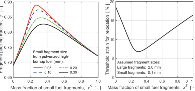
expressions for estimating G based on the particle characteristics also exist; see [13] and references therein. For our applications, G ranges from about 40 to 150, depending mainly on the relative difference in fragment size between the large and small fragment class. Fig. 1 shows the calculated fuel fragment packing fraction as a function of x , assuming four S different sizes for the small fragments, while the large fragments are assumed to be 2.0 mm in size. Obviously, the binary mixture has a peak packing fraction for 0.25 < x < 0.35. S The peak value, as well as the location of the peak, depends on the difference in size between the large and small fragments. In our model, we set the characteristic size of the small fragment class to 0.1 mm, which means that the overall fragment packing fraction can reach values above 0.85.
By combining the calculated curve for the 0.1 mm fragment size in Fig. 1 with eq. (2), we may calculate the threshold cladding strain for local fuel mass increase by axial relocation as a function of the relative amount of small fuel fragments. The results, which are presented in Fig. 2, show that the threshold strain decreases rapidly as the mass fraction of small fragments increases from zero to about 30 %, and then increases again. Experimental data in support of the cladding strain threshold in Fig. 2 are available only for low and medium burnup fuel with x = 0. For example, Siefken [3] evaluated 18 test rods with burnup < 35 S MWd/kgU and concluded that no axial fuel relocation occurred for cladding strains < 17 %. Likewise, Raynaud [7] reported a threshold cladding strain of 13–17 % for two Halden IFA-650 test rods with burnups of 56 and 61 MWd/kgU.
Fig. 1: Fuel fragment packing fraction vs. relative amount of small fragments from pulverized high
burnup fuel, calculated through eqs. (3)-(4).
Fig. 2: Cladding threshold hoop true strain for onset of axial fuel relocation vs. mass fraction of small fragments, calculated through eq. (2).
2.3 Modified equation for radial heat conduction
Calculated results from our relocation model are used for modifying the fuel rod temperature calculations in FRAPTRAN-1.5. Firstly, the changes caused by fuel relocation on the axial distributions of fuel mass, stored heat and power along the fuel rod are accounted for. Secondly, when the fuel pellet column collapses in ballooned segments of the fuel rod, we consider the changes in geometrical configuration as well as effective material properties. The pellet-cladding gap is significantly reduced, while gas-filled voids open up between the disorderly stacked fuel fragments. Since the volume fraction of gas is typically 20–30 %, the macroscopic thermal conductivity of the crumbled fuel in the balloon is much lower than that of solid fuel material. Consequently, the net outcome of fuel crumbling on the fuel radial temperature distribution is a lower fuel temperature close to the cladding surface (due to a reduced pellet-cladding gap) and a steeper radial temperature gradient (due to a low macroscopic thermal conductivity of the solid-gas mixture). To account for these effects, we modify the radial heat conduction equation in the fuel
) , ( 1 r t q r T r r r t T cpf f f
,
(5)which is solved in FRAPTRAN-1.5 for each axial segment of the fuel rod separately. Here, T is temperature, r is the radial coordinate,
q
denotes the volumetric heat source, and f ,fand c are the density, thermal conductivity and specific heat capacity of the fuel material. pf
The modified equation reads
) ~ , ( ~ ~ ~ ~1 r r Tr q t r r t T cpf eff f
.
(6)Hence, the fuel density and volumetric heat source are scaled with the fuel fragment packing fraction and the fuel thermal conductivity is replaced with an effective thermal conductivity for the crumbled fuel. This property, eff, depends on the thermal conductivities of the solid fuel fragments and the surrounding gas, and on the packing fraction of the fuel fragments [13]. Moreover, the positions of the nodes used for solving the heat conduction equation by the finite difference technique in FRAPTRAN-1.5 are scaled (r ), such that the collapsed r~
pellet surface comes into contact with and follows the distending cladding.
3. Model validation against the Halden IFA-650.4 LOCA test
3.1 Test conditions
The Halden IFA-650.4 LOCA test was conducted in April 2006, using a test rodlet with an average fuel burnup of 92.3 MWd/kgU. The test resulted in cladding ballooning and burst, as well as significant axial fuel relocation and dispersal of pulverized fuel into the coolant. The IFA-650 test rig and typical testing procedures are described in [4]. In short, a single test rodlet with an active (fuelled) length of about 500 mm is instrumented and placed in the centre of the rig, which in turn is placed in one of the experimental channels of the Halden test reactor. The rodlet is surrounded by an electrically heated shroud and a pressure flask. The latter is connected to a water loop that may be depressurized into a large blowdown tank to simulate a LOCA. During the test, a low and constant heat generation rate is maintained in the test rodlet to simulate decay heat, whereas the electrical heater simulates the heating from surrounding fuel rods. After the blowdown phase, the test rodlet heats up with a rate that depends on the predetermined power levels of the rod and the electrically heated shroud. Small amounts of water are periodically injected during this high temperature phase to maintain a sufficient amount of steam for cladding oxidation, but otherwise, no actions are taken until the test is terminated by switching off the electrical heater and scramming the reactor. The test rodlet is then left to cool down slowly, without quenching. In the IFA-650.4 test, the linear heat generation rate of the rodlet and heater was about 1.0 and 1.5 kW/m, respectively. The reactor was scrammed 617 s after initiation of blowdown, which defines the starting point of the test (henceforth referred to as t = 0). Cladding rupture was detected at t = 336 s. The design specifications and pre-test conditions for the IFA-650.4 test rodlet are summarized in Table 1. The rodlet was sampled from a full length UO2 fuel rod that had been
operated for seven reactor cycles in a commercial PWR. The rodlet had a Duplex-type Zircaloy-4 cladding with a 100 µm thick outer surface liner of Zr-2.6wt%Nb [4].
Rodlet design: Fill gas properties:
Active (fuelled) length [ mm ] 480 Composition [ vol% ] 95Ar + 5He
Cold free volume [ cm3 ] 21.5 Pressure at 295 K [ MPa ] 4.0
Fuel pellet properties: Cladding tube properties:
Material UO2 Material Duplex
Enrichment of 235U [ wt% ] 3.5 As-fabricated diameter [ mm ] 10.75
As-fabricated diameter [ mm ] 9.13 As-fabricated wall thickness [ mm ] 0.725 As-fabricated height [ mm ] 11.0 Pre-test oxide layer thickness [ µm ] 10–11 Pre-test average burnup [ MWd/kgU ] 92.3 Pre-test hydrogen concentration [ wppm ] 50
3.2 Methodology
As a preparatory step in our computer analyses, we used the FRAPCON-3.5 program [17] to model the pre-irradiation of the fuel rod segment that was later re-fabricated into the IFA-650.4 test rodlet. Calculated end-of-life results for the permanent deformations of fuel and cladding, cladding oxide layer thickness and hydrogen content, as well as the radial distributions of fuel burnup and power were used as input to the main analysis step, which involved modelling of the actual LOCA test with our extended version of FRAPTRAN-1.5. Only the first 500 seconds of the test were modelled. The fuel and heater power was held constant during this period, and no water was sprayed into the test rig. Consequently, the thermo-hydraulic boundary conditions for the rodlet were fairly simple and could be derived from temperatures and pressures measured in different parts of the test rig; a detailed description of the methodology is given in [13]. It should be made clear that our extended version of FRAPTRAN-1.5 includes not only the axial fuel relocation model described here, but also a set of models that treat cladding high temperature metal-water reactions, solid-solid phase transformation, creep and failure in a unified fashion [18]. All computations were carried out with best-estimate models, but the cladding high temperature creep rate was scaled by a constant to match the calculated and measured time to cladding rupture. The test was simulated twice, with and without the model for axial fuel relocation, in order to assess the importance of the relocation to the thermo-mechanical behaviour and high temperature degradation of the test rod. Other models were identical for the two cases.
3.3 Results and discussion
Our analyses of the IFA-650.4 test suggest that cladding ballooning, collapse of the fuel pellet column, and axial relocation of fuel take place in a fairly short (7–8 s) period before cladding rupture, but that the thermal feedback effects from axial fuel relocation are still strong enough to affect the rupture process. Fig. 3 shows the calculated evolution of cladding deformation and axial fuel relocation during the last seven seconds before cladding rupture, i.e. from the time when the balloon starts to grow and fuel starts to relocate.
Fig. 3: Calculated evolution of cladding deformation (left) and fuel relocation (right) during the last seven seconds before cladding rupture. The rightmost (red) curve represents the conditions at time of clad-ding rupture, while the seven curves to the left show the calculated state 1,2,3,...7 seconds before rupture. Data from post- test cladding diameter measurements are includ-ed for comparison (left). A post-test gamma scan image of the IFA-650.4 test rig, showing the amount of fuel loss from the upper part of the rodlet, is also included (right).
The fuel mass fraction (local ratio of current fuel mass to initial mass) reaches about 3 in the most distended cross section of the test rod, and the uppermost 120 mm long part of the rod is emptied of fuel. According to our model, the entire fuel pellet column has been pulverized into fine fragments before the relocation starts, which means that the fragment packing fraction is 0.72 everywhere in the region with crumbled fuel; see section 2.2.
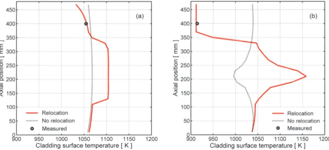
The calculated time to cladding rupture was 335.2 s with fuel relocation and 352.1 s without, which means that the calculated time to rupture was shortened by no less than 17 s as a result of thermal feedback effects from fuel crumbling and relocation. These feedback effects are illustrated in Fig. 4, which shows the cladding outer surface temperature versus axial position, calculated with and without consideration of axial fuel relocation. Measured data from a thermocouple located 400 mm above the bottom of the fuel pellet column are included for comparison.
Fig. 4: Calculated cladding outer surface temperature vs. axial position at t = 336 s, which is the time of cladding rupture (a), and at time t = 500 s (b). Calculations were made with and
without consideration of fuel relocation. Measured data are included for comparison.
It is clear from Fig. 4 that there is a significant difference between the calculated temperature distributions at time of rupture and at the end of the test for the case with fuel relocation. Somewhat surprisingly, as shown in Fig. 4a, the calculated cladding temperature increase along the balloon is almost uniform at time of cladding rupture. This is because the instantaneous cladding temperature increase in the balloon just after fuel crumbling is caused not so much by the local increase of fuel mass, but by closure of the pellet-cladding gap as the fuel pellet column collapses and hot fuel fragments come into contact with the cladding inner surface. Hence, the local increase of fuel mass in the balloon results in only minor thermal feedback effects before cladding rupture, but it has significant effects on the local cladding temperature and oxidation rate after rupture, as shown by Fig. 4b. This is also illustrated by Fig. 5, which shows the calculated equivalent cladding reacted (ECR) versus axial position. It is clear that the calculated contribution to the peak ECR from the LOCA test is about twice as large when axial fuel relocation is considered.
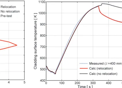
Finally, Fig. 6 shows a comparison of the calculated cladding surface temperature with the measured temperature evolution. The calculated curve for the case with axial fuel relocation is very close to the measured data. This confirms that thermal feedback effects of the complete fuel loss from the upper part of the rodlet are accurately captured by our model.
Fig. 5: Calculated equivalent cladding reacted at time t = 0 s (Pre-test) and t = 500 s, with and without consideration of axial fuel relocation.
Fig. 6: Calculated and measured cladding surface temperature vs. time at a position 400 mm above the bottom of the fuel pellet column.
4. Concluding
remarks
Our simulations of the Halden IFA-650.4 LOCA test with a novel model for axial fuel relocation, which is fully integrated in the FRAPTRAN-1.5 computer program, suggest that thermal feedback effects from fuel relocation are strong enough to significantly affect the dynamics of cladding ballooning and rupture, even though the calculated duration of these processes is no more than 7–8 s. Moreover, for the considered test, the axial relocation has a strong effect on the calculated peak cladding temperature and oxidation after cladding rupture. Validation of the model against additional LOCA tests is underway to assess the generality of these observations. It should be borne in mind that the IFA-650.4 LOCA test was deliberately designed to amplify axial fuel relocation, and it may therefore not be representative of actual conditions under LOCA in commercial power reactors [8].
Our work also suggests that “pulverization” of high burnup fuel is important to axial fuel relocation during LOCA, since it has the potential to increase the packing fraction of crumbled fuel. The pulverization thereby eases axial movement of the fuel pellet column and also raises the local heat load in regions where fuel fragments accumulate. The calculated results shown in Fig. 2 suggest that fuel with about 30 wt% small fragments created by pulverization would be particularly sensitive to axial relocation. From the empirical threshold for fuel pulverization in [6], this weight fraction of small fragments is expected when overheating LWR fuel with a pellet average burnup of around 72 MWd/kgU.
Acknowledgement
This research was funded by the Swedish Radiation Safety Authority (SSM) as part of the IAEA Coordinated Research Project FUMAC – Fuel Modelling in Accident Conditions.
5. References
1. Karb, E.H., et al., LWR fuel rod behavior in the FR2 in-pile tests, simulating the heatup
phase of a LOCA, 1983, Report KfK-3346, Kernforschungszentrum Karlsruhe, Karlsruhe,
Germany.
2. Broughton, J.M., et al., PBF LOCA test series: Test LOC-3 and LOC-5 fuel behavior
3. Siefken, L.J. Axial fuel relocation in ballooning fuel rods, 1983. In: 7th International
Conference on Structural Mechanics in Reactor Technology (SMiRT-7), August 22-26, 1983, Chicago, IL, USA.
4. Kolstad, E., et al. High burn-up fuel behaviour under LOCA conditions as observed in
Halden experiments, 2011. In: IAEA Technical Meeting on Fuel Behaviour and Modelling
under Severe Transient and Loss-of-Coolant Accident (LOCA) Conditions, October 18-21, 2011, Mito, Japan: International Atomic Energy Agency, IAEA-TECDOC-CD-1709. 5. Flanagan, M., et al., Post-test examination results from integral, high-burnup, fueled
LOCA tests at Studsvik Nuclear Laboratory, 2013, Report NUREG-2160, U.S. NRC,
Washington, DC, USA.
6. Yagnik, S., et al. An investigation into fuel pulverization with specific reference to
high-burnup LOCA, 2014. In: 2014 Water Reactor Fuel Performance Meeting (WRFPM
2014), September 14-17, 2014, Sendai, Japan.
7. Raynaud, P.A.C., Fuel fragmentation, relocation and dispersal during the loss-of-coolant accident, 2012, Report NUREG-2121, U.S. NRC, Washington, DC, USA.
8. Wiesenack, W., Safety significance of the Halden IFA-650 LOCA test results, 2010,
Report NEA/CSNI/R(2010)5, OECD Nuclear Energy Agency, Paris, France.
9. Aounallah, Y., et al. Simulations of the Halden IFA-650.3/.4 high burnup LOCA tests with
TRACE and FALCON; A preliminary study on axial relocation, 2006. In: 2006
International Meeting on LWR Fuel Performance (TopFuel 2006), October 22-26, 2006, Salamanca, Spain: European Nuclear Society, pp. 305-311.
10. Khvostov, G., et al. Modeling the effects of axial fuel relocation in the IFA-650.4 LOCA
test, 2007. In: Enlarged Halden Programme Group Meeting, March 12-15, 2007,
Storefjell, Norway: OECD Halden Reactor Project, Halden, Norway.
11. Govers, K. and M. Verwerft. Simulation of ballooning and relocation in the Halden LOCA
tests with FRAPTRAN, 2014. In: Enlarged Halden Programme Group Meeting,
September 7-12, 2014, Røros, Norway: OECD Halden Reactor Project, Halden, Norway. 12. Geelhood, K.J., et al., FRAPTRAN-1.5: A computer code for the transient analysis of
oxide fuel rods, 2014, Report NUREG/CR-7023, Vol. 1, Rev. 1, PNNL, Richland, WA,
USA.
13. Jernkvist, L.O. and A.R. Massih, Models for axial relocation of fragmented and
pulverized fuel pellets in distending fuel rods and its effects on fuel rod heat load, 2015,
Report 2015:NN Swedish Radiation Safety Authority, Stockholm, Sweden.
14. Oberländer, B.C. and W. Wiesenack, Overview of Halden reactor LOCA experiments
(with emphasis on fuel fragmentation) and plans, 2014, Report IFE/KR/E-2014/001,
Institute for Energy Technology, Kjeller, Norway.
15. Jernkvist, L.O. and A.R. Massih. Modelling axial relocation of fragmented fuel pellets
inside ballooned cladding tubes and its effects on LWR fuel rod failure behaviour during LOCA, 2015. In: 23rd International Conference on Structural Mechanics in Reactor
Technolog (SMiRT-23), August 10-14, 2015, Manchester, UK.
16. Westman, A.E.R., The packing of particles: Empirical equations for intermediate
diameter ratios. Journal of the American Ceramic Society, 1936. 19: pp. 127-129.
17. Geelhood, K.J. and W.G. Luscher, FRAPCON-3.5: A computer code for the calculation
of steady-state, thermal-mechanical behavior of oxide fuel rods for high burnup, 2014,
Report NUREG/CR-7022, Vol. 1, Rev. 1, PNNL, Richland, WA, USA.
18. Manngård, T. and A.R. Massih, Modelling and simulation of reactor fuel cladding under
loss-of-coolant accident conditions. Journal of Nuclear Science and Technology 2011.
![Table 1: Design specifications and pre-test conditions for the IFA-650.4 test rodlet [4]](https://thumb-eu.123doks.com/thumbv2/5dokorg/4142618.88766/6.892.117.778.933.1125/table-design-specifications-test-conditions-ifa-test-rodlet.webp)