U
SING
D
ISTRIBUTED
A
CTIVE
R
EAL
-T
IME
D
ATABASES
MATS LUNDIN
Submitted by Mats Lundin to the University of Skövde as a dissertation towards the degree of M.Sc. by examination and dissertation in the Department of Computer Science.
September 1998
I hereby certify that all material in this dissertation which is not my own work has been identified and that no work is included for which a degree has already been conferred on me.
__________________________________________________________ Mats Lundin
From the field of control theory, we can see that varying communication delays in a control system may be hard or even impossible to handle. From this point of view it is preferable to have these delays bounded and as small and as possible in order to adapt the control process to them. On the other hand, in some cases delays are inevitable and must be handled by the control system.
A control system may for different reasons be distributed, e.g., because of a distributed environment or severe environment demands such as heat or dust at some locations. Information in such a system will suffer from delays due to transportation from one place to another. These delays often show up in a random fashion, especially if a general network is used for transportation. Another source of delays is the system environment itself. For predictability reasons a real-time database is preferable if the delays are to be controlled.
A straightforward way of handling delays in a control system is to build the system such that delays are constant, i.e., to build a time invariant system. The time from sensor reading to actuation is made constant either by adding a suitable delay to achieve a total constant delay or by using time-triggered reading and actuation. These are simple ways of controlling the delays, but may be very inefficient because worst-case execution time must always be used. Other ways of handling varying delays are by using more tolerant control algorithms. There are two suitable control models proposed by Nilsson (1998) for this purpose. The tolerant algorithm approach is assumed in this work.
This thesis uses a distributed active real-time database system as a basis for building control systems. One of the main objectives is to determine how active functionality can be used to express the control system, i.e., how rules in the database can be used to express the control algorithm and for handling propagation of information. Another objective is to look at how the choice of consistency level in the database affects the result of the control system, i.e. how different consistency level affects the delays. Of interest is also to characterize what type of applications each level is suited for.
1 INTRODUCTION... 1
1.1 ORGANIZATION OF THE DISSERTATION... 2
2 BACKGROUND ... 5
2.1 CONTROL SYSTEMS... 5
2.1.1 Real-Time Systems... 6
2.1.2 Feedback Control Systems ... 8
2.2 TIMING PROBLEMS IN CONTROL SYSTEMS... 12
2.2.1 Modeling and Control of Delays in Control Systems ... 14
2.3 DISTRIBUTED REAL-TIME DATABASE SYSTEMS FOR CONTROL SYSTEMS... 17
2.3.1 Active Behavior: Rules ... 20
2.3.2 DeeDS Architecture... 21
3 PROBLEM DEFINITION... 24
3.1 MOTIVATION... 24
3.2 PURPOSE OF DISSERTATION... 25
3.2.1 Objective: Use of Rules for Control ... 26
3.2.2 Objective: Study Delay Dependency of Rule Distribution Schemas... 27
3.2.3 Objective: Investigate How can Rules Support Distribution... 28
3.3 ASSUMPTIONS... 28
4 EXPRESSING CONTROL SYSTEMS USING ACTIVE RULES ... 29
4.1 IMPLEMENTATION USING ACTIVE RULES... 29
4.1.1 Information Flow of Control Process... 31
4.3 IMPORTANCE OF RULE ORDERING... 40
5 DISTRIBUTION OF CONTROL FUNCTIONS ... 43
5.1 ISSUES IN DISTRIBUTING A CONTROL APPLICATION... 44
5.2 HANDLING RANDOM TIME-DELAYS IN SYSTEM... 50
5.2.1 Using Tolerant Control Algorithms... 51
5.2.2 Calculating Delays ... 51
5.3 WHERE TO DISTRIBUTE FUNCTIONS... 52
5.3.1 Delays in Different Allocation Schemas... 54
6 RESULTS... 56
6.1 IMPLEMENTING CONTROL APPLICATION USING ACTIVE RULES... 56
6.2 DISTRIBUTION OF CONTROL SYSTEM... 59
6.2.1 Issues in Distributing the Rules... 59
6.2.2 Compensating Delays... 60
6.2.3 Allocation of Rules ... 61
6.2.4 Using Databases for Control Systems ... 62
6.2.5 Level of Consistency ... 63
6.2.6 Discussion of ASAP Replication versus Bounded-Delay Replication ... 66
7 RELATED WORK ... 67
7.1 ACTIVE RULES FOR DATA MANAGEMENT IN CONTROL APPLICATIONS... 67
7.2 ACTIVE DATABASES IS SEMICONDUCTOR MANUFACTURING... 68
7.3 DATABASE FOR CIM APPLICATIONS... 69
7.4 A DISTRIBUTED DATABASE USED IN A COLD TANDEM MILL... 69
7.5 MODELING AND DESIGN OF DISTRIBUTED CONTROL APPLICATIONS... 69
8 CONCLUSIONS ... 73
8.1 SUMMARY... 73
8.1.1 Expressing Control System Using Active Rules... 74
8.1.2 Distribution of Control System Rules ... 75
8.1.3 Other Conclusions... 75
8.2 CONTRIBUTIONS... 77
8.3 FUTURE WORK... 78
ACKNOWLEDGMENTS ... 80
1.1 Overview of the problem area 3
2.1 A closed loop control system with delays 9
2.2 Markov chain and delay distributions 16
2.3 The DeeDS architecture 22
3.1 The four allocation schemas 27
4.1 A simple control system 31
4.2 A control system with an estimator 32
4.3 Rule for compensating transients 39
5.1 Control system with several sensors 45
5.2 Control system with delays 46
Introduction
Future feedback control applications will operate in distributed environments that involve large volumes of data. The development of such applications can be tedious unless tools are available for building these applications on a suitable platform. As a result of the distributed nature of such applications, delays will be present, and may cause instability unless the delays are compensated for. These delays are often random, as the communication between the nodes in the system often takes place via a general network. There are proposals for how to compensate for unpredictable delays in those systems [Luc90], and for using more delay-tolerant control algorithms [Cha96, Nil98, Ray94]. Recently, there has been some work done on building distributed feedback control applications using such tolerant control algorithms, e.g., see [Nil98, Tör95].
A distributed database offers a way of handling large volumes of data and distribution it in a natural way, and thus, can be a suitable platform for building
distributed control systems. The time for replication of data between the nodes will be random due to unpredictable network delays.
This dissertation address the area of building distributed control systems using an active distributed real-time database as the base. We examine how a control application can be modeled using active rules in order to implement it in the database. Then we examine the issues that are raised as the control application is distributed, i.e., by partitioning of the rules to the different nodes in the database. We look at how tolerant control algorithms can be used to compensate for delays in database replication.
It is shown that a control application, as well as management control functions, can be implemented using active database rules. There will not be any conflicts in rule ordering as long as some special case of management control functions are used. An ordinary control system will have the same information flow independent of where the rules are placed. The delays in the control system can be calculated (and compensated for) if the times when the information written in the database are known. An overview of the problem area of this dissertation is provided in figure 1.1.
1.1 Organization of the Dissertation
Chapter 1 has presented an introduction to the area of building distributed feedback
control systems.
Chapter 2 gives an overview of real-time and feedback control systems, delays in
Figure 1.1 - Overview of the problem area
Chapter 3 presents the problem definition of this dissertation. The motivation, aims and
objectives are presented.
Chapter 4 describes how a control application is expressed using active rules. Both
basic control functions in control theory and additional functions for building control systems are presented.
Process Controller Estimator Measured outputs Set points Estimates of unmeasured outputs Manipulated variables
ON update(t) IF - THEN calculate(t) ON interrupt1 IF - THEN write(t) ON update(x) IF - THEN actuate(x) ON interrupt1 IF - THEN write(s2) ON interrupt1 IF - THEN write(s2)
… …
ON update(t) IF (t-t.prev)>transient THEN f_actuate(t)
ON update(t) IF - THEN calculate(t) ON interrupt1 IF - THEN write(t)
Expressing the control system into active rules and implementation of other control functions
Distribution of the active rules to the database nodes, and compensation for delays
Chapter 5 describes how the control system is affected by the delays introduced by
database replication and what can be done to compensate for them.
Chapter 6 gives the results and discusses what is important when building control
system using active rules.
Chapter 7 presents work done in close relation to this dissertation, and compares it to
the work done here.
Chapter 8 summarizes the dissertation and contributions are highlighted. Some
Background
This chapter introduces areas important to the dissertation. The following is an introduction to control systems (section 2.1), timing problems in control systems (section 2.2) and distributed real-time databases for control systems (section 2.3).
2.1 Control Systems
The use of computers for control purpose is of great importance in the automation of real-world processes, such as chemical plants and CIM (Computer Integrated Manufacturing) environments. The most general way of using a computer for control is to have sensors connected to a computer, a control program and actuators that affect the real world processes according to decisions made by the control program. This way of building a control system may be sufficient for simple control problems where the demands are not be too rigorous. For other problems the control system must be built with greater care, e.g., because the controlling must be exact and reliable in all situations or if the control problem is distributed by its nature.
Definition 1 - A general control system is a system that continuously uses updated
information about an environment for making decisions or calculations and delivers an output.
In order to achieve total control over a controlled environment, data is fundamental [Rod89]. In this dissertation we consider how an active distributed real-time database (active RTDB) can be used as the basis for building process control systems (see further section 3.2), i.e., systems that controls a continuous processes.
There are two fundamental types of control systems used in the computer science and engineering field, respectively. In computer science, a real-time system is a control system that reacts to the controlled environment in a timely manner. Such systems mostly operate in environments where events or timer interrupts are used to start computations that result in discrete events. In section 2.1.1, such real-time systems are described. On the engineering side, control theory is used to control continuous real-world processes. Today many control systems use sampled data and a computer to perform the computation. In section 2.1.2, such control systems are described.
2.1.1 Real-Time Systems
A real-time system is built to deal with the dependability aspects1of a control system
and to ensure its correct behavior in a timely manner, i.e., within a bounded time. The terms “time-critical” and “real-time” do not necessarily imply very fast execution, but
1
fast enough for the chosen application. In [Bur97] a real-time system can be defined in the following way:
Definition 2 - A Real-Time System is a system that is required to react to stimuli from the environment (including the passage of physical time) within time intervals dictated by the environment.
Some of the dependability aspects that individually must be considered and handled by real-time systems are [Lap94] and [Mul94]:
• Availability – the delivery of correct service when needed, i.e. readiness for usage.
• Reliability – continuous delivery of correct service over time.
• Safety – non-occurrence of catastrophic consequences as a result of one or more
failures.
• Maintainability – ability to quickly undergo repairs and reintegration of system.
The time at which the output of the system must be produced is called a deadline. Deadlines are categorized according to their criticality depending of how important it is to finish in time. If a missed deadline is of catastrophic nature the system is said to be hard critical. A soft real-time system is a system where the missed deadline is of the same magnitude as the utility of the operational system [Mul93]. The systems can further be classified into the following criticality classes according to the consequences of missed deadlines [Bur91]:
• Hard critical – a missed deadline leads to catastrophic consequences as great
economic loss, great environmental pollution, injury, or even death.
• Hard essential – costly penalty, e.g., damage of equipment or material.
• Firm – loss of service, e.g., a missed departure or plane reservation.
• Soft – degraded service, e.g., loss of certain functions as less optimal fuel
consumption, less smooth ride etc.
Another important design aspect of real-time systems is the way they respond to external events, either the system is event triggered or time triggered. An event-triggered system is a system where the execution is dependent on externally generated events, e.g., sensor readings. A time-triggered system on the other hand uses the system clock to trigger the execution. The former system executes within a bounded time from the generation of the event and the latter uses the clock to execute at pre-defined points in time. This means that delays in an event-triggered system can be less than in the time-triggered system, but the execution is easier to predict in the latter.
2.1.2 Feedback Control Systems
A feedback control system is a special case of a control system that controls a continuous process by feedback. This is done by sampling the readings from the sensors at precise points in time, i.e., it is a time-triggered system with a given sampling interval.
Definition 3 – “A feedback loop is a control system in which a desired effect is
achieved by operating on various inputs to a controlled system until the output, which is a measure of the desired effect, falls within an acceptable range of values.” [Tör98]
In this work we will from now on refer to a feedback loop when we use the term
control system.
Figure 2.1 - A closed loop control system with delays2.
The principles of a sampled data system are illustrated in figure 2.1, see further in Törngren [Tör95]. The information in such a system is a mixture of both continuous and discrete time signals, here illustrated with continuous and dashed lines respectively. The connection between the controller and the real world goes through the analog to digital (A/D) and digital to analog (D/A) converters. Time delays in the system are modeled by τ, where τc is the controller delay (computation time), τsc is the
r(k) is the desired output reference, u(t) is the control signal to the actuator, y(t) is the
actual output and y(k) is the sampled output.
In control theory PID-controllers are usually used since it is simple and handle many situations. The P stands for Proportional, it compensates for the error, i.e., the difference between the actual and the desired output. The I stands for Integration, and integrates the error over time to reduce it as close as possible to zero. Finally, the D is for Derivation. The error value is derived to be able to compensate for fast changes. In a control system there are constants, called the system variables, that are used in the computation of the output to the actuators.
Sampled data systems are in general time invariant, i.e., the delays in both the control algorithm and in conversions are constant due to the electronic circuit properties. This time invariant view is mostly sufficient for feedback control purposes. In a distributed environment this might not be sufficient as delays are introduced. There is a straightforward way of handling too long response delays, it is to raise the sample rate. A rule of thumb is to choose a sample rate of 10-30 times the desired natural frequency of the closed loop system [Åst90], i.e., the frequency that the system will oscillate with if the control system is too slow.
This type of control is, nevertheless, sensitive if delays are introduced [Cha95], because the delays is not compensated for in the model of the environment that the control system is built for. This means that the control performance is affected as
2 Modified figure from [Tör95]
delays are introduced to a system that is not designed to handle them. For example, a consequence might be that the system starts to oscillate because the system is late to compensate for an error in the output [Nil96]. In this dissertation we will only look at
the influence of τsc and τca. The effect of τc can be embedded in τca [Nil96].
The change from sample to sample are normally small, a control system is built fast enough to be able to handle these changes. However, there may be fast changes in the environment that the system is not fast enough to handle, these are called transients.
In this dissertation we assume that a control system can be decomposed into the following basic parts, each called a control function:
• Sensor reading – The sampling of the sensor value.
• Actuation – The actuation of the output from the control algorithm.
• Control algorithm – The computations to compensate for the error between the
actual and desired value.
• Digital filter – A filter in the computer that smoothes the sensor readings.
• Estimator – A function for deriving values that are not directly measured, e.g.,
other values must be used to indirectly calculate the extreme heat of a gas.
Definition 4 – The term control performance is used as a measure of system
performance, a better accordance to a wanted behavior is named better control
The flow of information in a control system we define as:
Definition 5 – A control process is the flow of information in a control system. The flow of information is defined by the information being passed from one control
function to another. The control process starts with the information written by one or several sensors and end when the control is being delivered to the actuator(s). A control process may have several paths of control as there may be several sensors and actuators.
2.2 Timing Problems in Control Systems
In most systems there are delays introduced in the system by different sources. In a centralized control system the most significant delay is usually caused by the control algorithm. If the system, on the other hand, must be built in a distributed manner, the
delays in communication (τsc and τca) become significant. The reason for building
distributed control system can be several [Mul93, p. 424, Cha95]:
• The sensor(s) and actuator(s) are at different physical locations.
• A computing element is used for several control process algorithms.
• The environment at the sensor and actuator representatives is too severe for a
computer control site to work in, e.g., by high heat, dusty environment or the signal noise of the computer might affect the process.
Time delays in a control system can be divided into two main types of delays, namely jitter and control delays [Tör95].
Definition 6 - Jitter is the non-intentional variation in sampling period.
Definition 7 - The Control Delay is the actual delay from sampling to actuation. In
terms of figure 2.1, it is the total delay τ = τc + τsc + τca.
Another source of delays is the clock drift between nodes in a distributed system. In this dissertation we clock drift as jitter and will therefore not consider it separately.
There may be situations where one sample is not measured or where it disappears before it reaches the actuator, this is called vacant sampling. Törngren in [Tör98] and Ray in [Ray88] propose that oversampling can be used to solve this situation, i.e., a sample period shorter than actually needed. It will however reduce the time-variations at the cost of increased resource utilization.
When more information is appearing more rapidly than is possible to send on the network a queue must be used for handling the transmission. In [Cha95] a way of handling delays in these situations. This will not further be discussed in this dissertation.
The delays introduced by communication in a distributed system are not always easy or even possible to predict, especially if a general network is used. In the case of a general network the delays are among others defined by the properties of the
communication media, e.g., the bandwidth and the latency of sending messages. Even if these properties are known there are other sources of delays as well such as the load and traffic patterns of the network causes unpredictable delays. Time-varying delays on control system performance and the modeling of time-varying discrete-time control systems were investigated in [Luc88].
It is not only the communication from one node to another that affects the delays in a distributed system, the choice of algorithm for distribution and synchronization is also affecting the total delays [Lun97].
2.2.1 Modeling and Control of Delays in Control Systems
Depending on the properties of the system, e.g., by consistency level, communication media, and algorithms for communication, the delays are of different kinds and can be categorized in three different ways:
• Constant delays – the delays are known in advance and do not change over time.
• Randomly and independent delays – the delays are not predictable and are totally
random over time, i.e., no variations in distribution caused by the load of the network, etc.
• Stochastic delays – the delays have a known distribution, e.g., by affection of
variations in network load.
The constant delays can be dealt with by the standard control theory and are only problems if they get too large, see e.g. [Sch88]. The method for controlling constant delays are called LQG-control, Linear Quadratic Gaussian control. The varying delays
are, on the other hand, a larger problem because of their unpredictability. There has recently been done work in this area and theories have been proposed for dealing with randomly independent delays [Ray94] [Nil98] and stochastic delays [Nil98].
A straightforward way of handling delays in a control system is to build the system such that the delays are constant, i.e., building a time invariant system. Firstly the time variations are reduced to a minimum by suitable choice or modification of the execution strategy. Secondly the time from sensor reading to actuation is made constant by either adding a delay to have a total constant delay or by using both time-triggered reading and actuation. Luck and Ray [Luc90] proposes a solution where buffers are used for compensation at the controller node and the actuator node. The problem with this method is that it is pessimistic and highly dependent on modeling accuracy, i.e., worst time delays must be considered.
In order to make a control model that manages delays it can be assumed that the transfer delay is independent of previous delays. A comparison between a model with constant delays and one with independent varying delays are done in [Nil96, Ray94].
The case in a distributed control system is not totally random delays but delays that are dependent of earlier delays, e.g., by network load at the moment. A way to model random but dependent delays is by using an underlying Markov chain [Krt94, Nil96, Nil98]. Having the system do a transition in the Markov chain every time a transfer is made can be used to capture effects of varying delays.
Example 5 - Markov chain (from [Nil96])
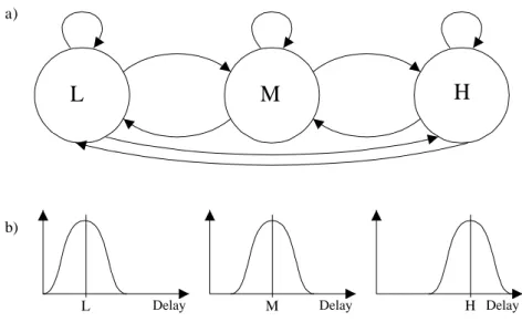
In a simple model of a network we can let the network have three states: One with low, medium, and high network load respectively. In figure 2.2, the Markov chain gives the transitions between the three network states. Together with each state in the Markov chain there is a corresponding delay distribution modeling the delay for that network state, e.g., by the one in figure 2.2.
Figure 2.2 - Markov chain and delay distributions
In 2.2 a) an example of a Markov chain modeling the states in a communication network. L is low, M is medium and H is high network load. The arrows show the possible transitions in the system. In b) the delays distribution is showed for each case respectively.
The models described above are suboptimal solutions to the control problem, but can be good tools for handling randomly varying delays in a system.
L
L
M
M
Delay Delay Delay
a)
b)
H
In this dissertation we will only consider control delays but not jitter in the system. This is because the control models described in [Nil96, Nil97, Nil98] does not take jitter into account.
2.3 Distributed Real-Time Database Systems for Control Systems
A distributed database is a database that has some common data distributed over several sites and allows coordinated sharing and updating of that data. One of the reasons for distribution is that the data must be reachable at several sites at the same time. An advantage compared to a conventional centralized database is fault tolerance and modular growth at each site [Mel97]. On the other hand, this also raises the issue of replication of changes from one node to another; there must be some synchronization that ensures consistent data at all nodes. The price for this synchronization is the use of a protocol that consumes processor and communication resources and also takes elapsed time to perform. This elapsed time is often hard to predict because of the unpredictability of the communication medium.
There are different protocols proposed for handling data consistency and for ensuring atomic execution of transactions in a database, i.e., to ensure that an operation is executed at all sites or none at all [Lun97]. A usual way is to use an atomicity
protocol which replicate the read and write transactions to all other nodes, one such
protocol is the Distributed Two-Phase Commit Protocol. This protocol and other further developments are all using considerable resources for execution.
In databases, so called ACID properties are used to specify a correct behavior of the database, e.g., to ensure its correct behavior. In [Gre93, Elm94] these properties are defined as follows:
• Atomicity – A transaction’s changes to the state are atomic: either all happen or
none happen. These changes include database changes and messages.
• Consistency – A transaction is a correct transformation of the state. The actions
taken as a group do not violate any of the integrity constraints associated with the state. This requires that the transaction is a correct program.
• Isolation – Although transactions execute concurrently, it appears to each
transaction, T, that others executed either before T or after T but not both.
• Durability – Once a transaction completes successfully (commits), its changes to
the state survive failures.
When we say that a database is distributed in this dissertation we will assume that all data is available at all nodes, i.e., the database is fully replicated.
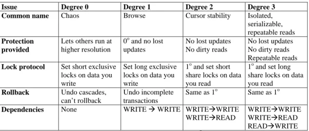
In close relation to the level of consistency is the level of isolation. In [Gre93] four levels (degrees) of isolation are identified, namely: 1) Chaos, 2) Browse, 3) Cursor Stability, and 4) Isolated. A closer comparison is done in table 2.1.
Issue Degree 0 Degree 1 Degree 2 Degree 3 Common name Chaos Browse Cursor stability Isolated,
serializable, repeatable reads Protection
provided
Lets others run at higher resolution 0o and no lost updates No lost updates No dirty reads No lost updates No dirty reads Repeatable reads Lock protocol Set short exclusive
locks on data you write
Set long exclusive locks on data you write
1o and set short share locks on data you read
1o and set long share locks on data you read
Rollback Undo cascades, can’t rollback
Undo incomplete transactions
Same as 1o Same as 1o Dependencies None WRITE à WRITE WRITEàWRITE
WRITEàREAD
WRITEàWRITE WRITEàREAD
READàWRITE
Table 2.1 - Description of the different levels of isolation3
In some cases it is not important to have immediate consistency, e.g., when an application is tolerant to temporal inconsistencies, but instead a more efficient usage of the resources is to prefer [Lun97]. In such cases an eventual consistency protocol can be used, i.e., a protocol that does not guarantee immediate consistency but consistency at some future point in time. The result of such a protocol is that an unknown time delay to achieve consistency of the database is introduced.
A way of controlling replication delays for critical transactions is to use different latency classes in the communication. This will make it possible to shorten some delays at the cost of lengthening others.
Traditional databases do not focus on real-time issues but on integrity and consistency of data. They often store the database on a secondary permanent storage medium such as a disk and do not have to take timely behavior into account. A
database for a real-time systems must take the access delays into account to ensure timely behavior. A way to do this is by using a main-memory database, which will also improve the performance [Lis97]. Also the time of creation are of greatest interest, since the data are only valid for a given period of time [Rod89]. A designer of a simple PID controller assumes that the data are measured at specific points in time.
2.3.1 Active Behavior: Rules
Traditional database systems only support operations such as insertions, deletions, and retrievals. In order to build systems with active behavior, e.g., for supporting business rules, the application programmer must explicitly do this. In a distributed environment, this is an even harder task. There are two fundamental ways of implementing rules in a distributed environment using an ordinary database [Fal96]:
• Embedded rules – An embedded rule is not a part of the database itself but a part of
the program code at each node. This means that the rule must be hard coded at the construction of the system and compiled to each node specifically. When a change in the database is propagated to the nodes in the system and the system should react to this change code must be written to handle this situation. As the information comes to a node, it must be evaluated whether it is relevant or not, and if so, trigger an action.
• Polling – the rules are enforced by a process that constantly scans the database for
changes and executes the corresponding rules if a relevant change is found. The polling procedure must be performed at each node in the database. An important
design consideration in an application using polling is at which frequency the polling should be performed.
Both of these approaches have drawbacks. The first approach means that the same rules must be programmed and executed at each node that uses or updates some relevant data. Maintenance and updating of applications using embedded rules is thus costly and changes in implementation may cause inconsistencies in data. The second approach uses a large amount of resources: processing power, communication bandwidth, and database usage. It also requires a trade-off between resource usage and time to discover changes. Further elaboration in the area can be found in [Fal96].
A better approach than using the proposed ways of implementing rules, active functionality can be integrated into the database itself. An active database system is such a database system that monitors situations of interest and, when they occur, triggers an appropriate response. In real-time database systems this must happen in a timely manner.
2.3.2 DeeDS Architecture
The DeeDS (Distributed active real-time Database System) architecture and prototype at University of Skövde is an attempt to keep up with the demands of timely behavior, complex environments and large storage capacity. It is an event triggered database system that uses dynamic scheduling and is built for flexibility [And95, And96, Mel97]. Transactions can be of different criticality and the reactive behavior is
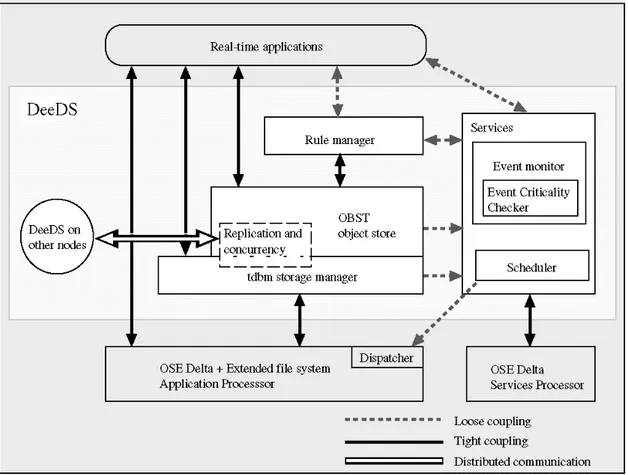
modeled using Event-Condition-Action rules. The architecture of DeeDS is shown in figure 2.3.
Figure 2.3 - The DeeDS architecture.
The application-related functions in DeeDS are separated from the critical services by running them on different processors. The reason for this is that it simplifies the timing model, i.e., is advantageous for predicting the temporal behavior. Each processor executes a distributed real-time kernel (OSE Delta).
The database used is a public domain object store, OBST (Object Management System of STONE) [Cas92], but the storage manager has been replaced with tdbm [Bra92]. The main reason for this is that tdbm supports nested transactions, which is a
desirable functionality in active databases and for exception handling and efficient main-memory access techniques. The reactive behavior in DeeDS are modeled after the event-condition-action (ECA) paradigm described in [Cha89].
DeeDS have two replication policies, namely as soon as possible (ASAP) [GUS95] and Bounded Delay [Lun97]. All transactions commit locally before the updates are replicated to the other nodes, requiring an eventual consistency protocol to be used. This gives a short latency within a physical node as the execution of next transaction can start immediately after the previous. In this dissertation we assume this local execution before replication.
Problem Definition
This chapter defines the purpose and motivation of this work and gives an overview of the problem that we wish to address in this dissertation. The main purpose is divided into objectives that can be evaluated.
3.1 Motivation
Building a control system today can be a very difficult task, there are often considerable information to take into account and the control process can be anything but trivial. In order to deal with the complexity in manageable way, a control problem can be divided into subproblems that individually can be solved in a satisfactory way. If a situation also raises the demand of distribution, e.g., by inherent geographic distribution or demands for fault tolerance, there are other types of problems raised:
• Transportation of information from one place to another
• Coordination of remote control system.
• Timing problems such as deadlines and delays
In a control system where a lot of information is to be used in a distributed environment, a platform that handles this automatically is to prefer. This is the reason why a distributed real-time database system is to be used as the basis. One of advantageous features of such a platform is the active functionality that can be used to express the control system at different places in the system. One of the big problems, on the other hand, is the delays that comes from the distribution of the platform.
There are mainly two ways of handling the problems of communication delays in a distributed control system, either from the computer science or the control engineering perspective. There are some work done on how to model different delays in control theory, e.g., for use in distributed real-time systems. There are, however, no specific study done in using a distributed real-time database for building a control system.
For simplicity and to ensure consistency the DB are the only medium to send information in the system. This also implies that rules must be used although they might be inefficient if used in to a large extent. On the other hand, few rules are activated at the same time, which improves the performance.
3.2 Purpose of Dissertation
The main purpose of this dissertation is to look at advantages and disadvantages of using active functionality in a distributed real-time database system when it is used for building distributed control systems. The first aspect of interest is whether a control system can be expressed using active rules and if some other control functions can be defined. Secondly, the delays introduced by the distribution of the rules are considered.
This also raises the question of whether precaution must be taken to maintain consistency in the database.
3.2.1 Objective: Use of Rules for Control
The active functionality of a database can be used with advantage in many situations. In this dissertation we will look at how rules can be used to express a distributed closed-loop control system.
Hypothesis 1 – Rules can be used to facilitate distribution and allocation of control.
In normal situations the environment that a control system works in is easy to handle and does not have any transients, i.e., fast or unforeseen changes in the process. To have a better control performance without utilizing the systems resources more than necessary a rule can be defined to handle this.
Hypothesis 2 – By using active rules of a distributed real-time database transients can be handled.
We will also have a look at how the level of consistency that a database delivers affects the delays. One interesting question that is investigated is whether an eventual consistency protocol with ASAP replication is sufficient for a control performance, or if bounded delay replication must be used.
3.2.2 Objective: Study Delay Dependency of Rule Distribution Schemas
One of the most obvious delays in the system depends on the network, which can be the most troublesome to predict. These delays depend not only on the inherent latency and bandwidth of the communication medium, but also of the network load, traffic patterns, topology, and protocol.
In a distributed control system there are four static allocation schemas possible, in addition to the trivial schema where the sensor, controller, and actuator are located at the same physical node. These four allocation schemas are shown in figure 3.1. Depending on which of these is used, the delays are present in different parts of the control process. These four allocation schemas are all evaluated with respect to the case where the sensor, control, and actuator are at the same node. A physical node is a separate processor with memory and a replica of the database. Each physical node can hold several control functions.
In figure 3.1 the physical node is defined by a dotted line. In 3.1 a) the sensor function and the control algorithm are at the same physical node, in 3.1 b) the actuator function and control algorithm are at the same physical node, in 3.1 c) all control functions are at separate physical nodes and in 3.1 d) the sensor function and actuator function are at the same physical node.
3.2.3 Objective: Investigate How can Rules Support Distribution
We investigate how rules can be used to distribute the control system to the different nodes in the system. When the rules are distributed there will be delays, and we examine how these affect the performance of the control system.
3.3 Assumptions
We make the following assumption in this dissertation:
• All communication between the control functions goes through the database. The
delay from two functions at the same physical node are insignificant compared to the delay in replication between two physical nodes.
• A time-driven sensor representative. The readings by the sensor are done
periodically, i.e., the sensor function will always have enough resources at the sample instant. The updating of one or several database variables triggers the other control functions, including the actuator function.
• The control algorithm keeps a history of previous delays.
Expressing Control Systems Using Active
Rules
In order to build a distributed control system with a distributed database the control system must in some way be expressed, either in separate code or in the database itself. The control functions in a control system are defined in section 2.1.2. In this chapter we consider how the control functions can be defined using active rules in an active RTDB and how these rules are combined into a control application. Some important aspects while building the control application are timely behavior and fast execution due to the control applications sensitiveness to delays.
4.1 Implementation Using Active Rules
In the area of control theory a control system consists of at least a control algorithm that performs the controlling of a physical process. Often there are other parts as well, depending on what process that is to be controlled. In this section the functions that a
control system can consist of are defined and expressed as rules. The reasons for expressing the control system into rules are:
• The possibility to use an active database as basis for the control system
• To allow distribution of the control system over several nodes
Further, the reason for distributing the control system over several nodes can be one or several of the following reasons:
• Hostile environment – There may be a severe environment where normal high
performance processors cannot work, e.g. in the reactor of a nuclear plant or in a dusty or hot environment.
• Distribution of system – The system representatives are distributed over a large
spatial area.
• Distribution of information – Information from one sensor can be used at several
locations in the whole system
In order to build a control system out of an active database the control system must be modeled into the database, i.e., into active rules. In the following section we examine the information flow in the database when it is used for control systems. Next is a section where the control functions are expressed into active rules and then a section where some management control functions are presented.
4.1.1 Information Flow of Control Process
There is a flow of information through a control system: The sensors produce new information, the control functions use it to calculate an appropriate behavior of the system and finally the actuators perform what is decided by the control functions. This flow of information must in some way be implemented into the database. One way of doing so is by using the rules to define an implicit information flow.
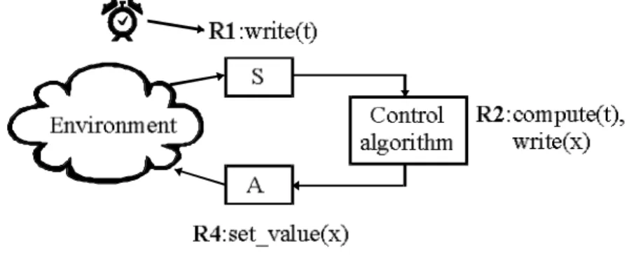
Figure 4.1 - A simple control system with a sensor, control algorithm and actuator
implemented in using active rules.
Example 6 – A simple control system consisting of a sensor, control algorithm, and an
actuator can be modeled by three active rules, see figure 4.1. The first rule (R1) is time-triggered and read a value from the sensor and writes it to the database. The second rule (R2) is trigged by the update and calculates the control value and puts it in the database. Finally the last rule (R4) is triggered by the second update and sets the new value to the actuator.
In some control applications the control algorithm uses information from multiple sources, e.g., from several sensors or from both a sensor and an estimator. One way of modeling this and to ensure a correct information flow of information is by using composite events to trigger a rule.
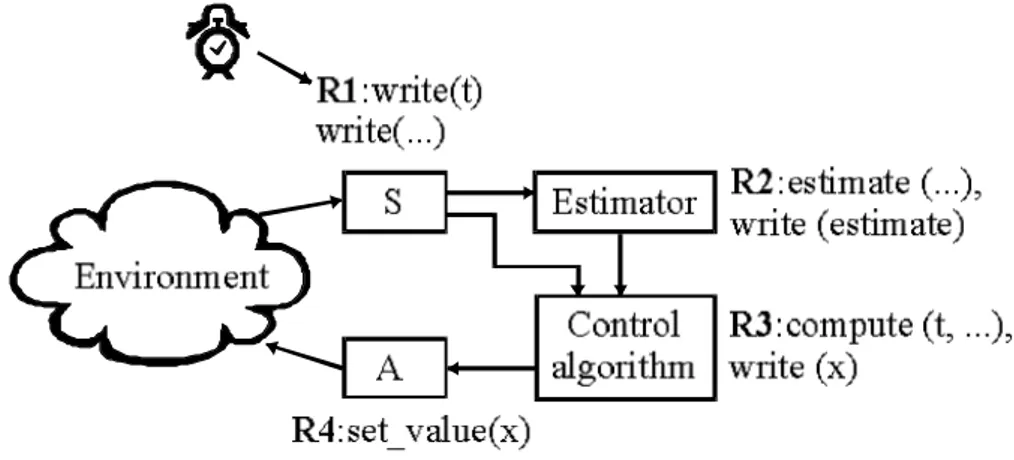
Example 7 – A control system with an estimator have multiple ways of information in
the control process, the control algorithm uses information both directly from the sensor and information that has been derived by the estimator (see figure 4.2). A composite event at the control algorithm ensures that new information from both the sensor and the estimator is available before the computation takes place.
Figure 4.2 - A Control system with an estimator implemented into active rules.
Each function (or rule) will write its result to the database. The value written by each function is unique and is not written by any other function. Thus, the control process is implicitly defined and only has one way trough the control system.
4.1.2 Basic Control Functions
The basic control functions (sensor reading, actuation, control algorithm, predictor, estimator, and digital filter) defined in section 2.1.2 all have one thing in common, namely they all process information. When information is received they calculate new values and deliver it as output. This commonality makes them all suitable to be expressed in the same way using active rules.
Example 8 – An example of expressing a control application into active rules.
A control application that consist of an estimator and a control algorithm is illustrated in table 4.1. Some of the measurements cannot be made in the process, but have to be estimated using an estimator.
There are four basic and separate control functions that can be identified to perform the actual control process, namely:
1. Sensor-reading – Information about the current status of the controlled system are
measured by sensors.
2. Estimator – Estimation of values that are hard or even impossible to measure
directly in the environment.
3. Control algorithm – The actual control process that calculates the new control
values to correct for a possible error compared to the desired behavior, e.g., speed, flow, position etc.
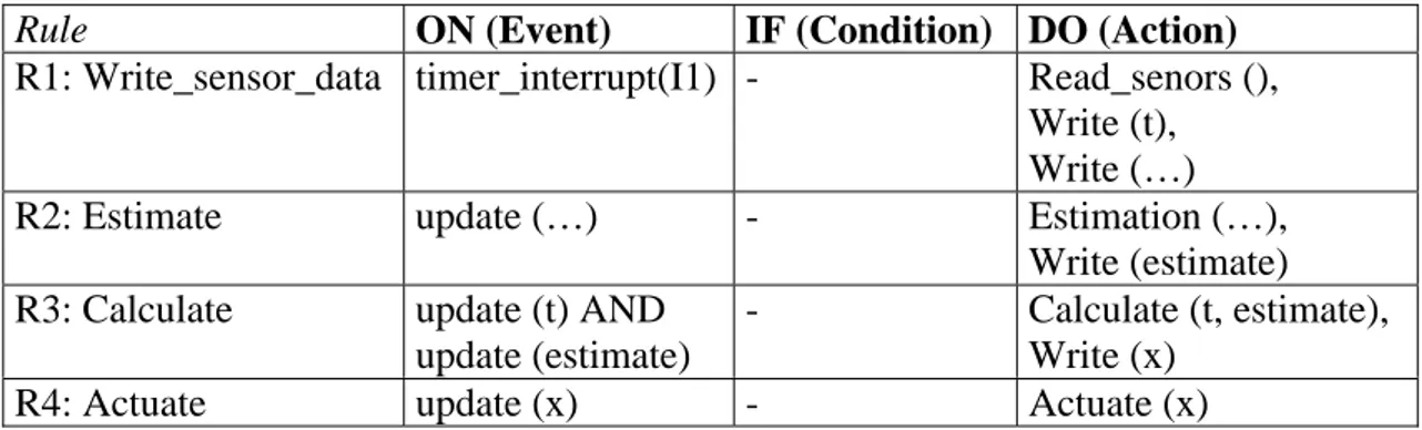
In this example the basic control functions can be implemented by active rules that uses the updating of the database as events, except for R1 that are trigged by a timer.
Rule ON (Event) IF (Condition) DO (Action)
R1: Write_sensor_data timer_interrupt(I1) - Read_senors (),
Write (t), Write (…)
R2: Estimate update (…) - Estimation (…),
Write (estimate)
R3: Calculate update (t) AND
update (estimate)
- Calculate (t, estimate),
Write (x)
R4: Actuate update (x) - Actuate (x)
Table 4.1 - The basic control functions implemented as ECA-rules.
In table 4.1 the basic control functions are implemented as ECA-rules. The first rule (R1) is trigged by a timer interrupt (I1). R1 reads the information from several sensors and write the values into the database. R2 is then trigged by the updating of the database variables (here represented by […]) written by R1. The estimation is calculated and written to the database. R3 is trigged by the composite event of update
(t) and update (estimate) which ensures that the control algorithm starts only when a
new and updated variable from the estimator is available. Finally, the fourth rule (R4) is trigged by the update of x in the database and x is sent to the actuator.
The other basic control functions (predictor and digital filter) are also possible to implement as rules in the same way as the control algorithm and the estimator. The event(s) that trigger a function is the update made by another basic control function(s) earlier in the control process.
4.1.3 Control Management Functions
A control application may be a control system that handles a simple process. On the other hand, the problem at hand can be a more troublesome process that must be treated with greater care. The usage of active rules gives the possibility to implement more functionality to the control application. We consider some functions that are of interest:
• Supervision – Some control applications work autonomous without any
supervision, while others are of greatest interest to a supervisor. There may be special situations when an alarm must be set to inform a supervisor.
• Adaptation to changes in environment – The environment that a control system
work within may change over time and to maintain a given control performance, the control system must adapt under run.
• Handling of other changes in environment – There may be other changes in the
environment such as disturbances that causes the control process to go out of hand. To prevent the system from a hazardous behavior actions must be taken.
• Handling of transients – An ordinary control system is built sufficiently fast for
handling changes in the environment. If faster changes appear the system may have an unwanted behavior or even become unstable. It is therefore desired to handle this.
• Handling vacant sampling – If, by some reason, new information from the latest
sensor reading does not show up at the controller the system must continue to work.
Supervision: The supervision of a process is either done periodically or at special
occasions, e.g., when a given threshold is passed. The supervision can consist in a message sent to a GUI or data written to a logfile for later inspection. In either case the same mechanism can be used.
Consider an active rule that triggers on the update of a database variable will capture all new data in the database. As the database is the only communication medium for information in the system the rule will therefor not win anything in checking the data more frequently. To specify this rule it is sufficient checking the
update event, i.e., an EA-rule can be used.
To check the environment for special occasions, an ECA-rule are used to specify if the occasion has occurred, i.e., if a given threshold has been passed. It is also possible to specify a rule that triggers if the actuator has not yet received an actuator value at the time of next sample instant. This can be done by an interrupt-driven rule at the same physical node as where the actuator function is.
Adaptation to changes in environment: The environment in which the control
system works within may change, e.g., by drastic changes in measured values or because the different units in a CIM-application must be treated differently.
An active rule triggering on a specific change in the environment can change the control system variables or even the information flow to adjust its operation.
Example 9 – Consider a CIM application where different parts can be manufactured.
The control system can adjust its parameters to have an optimal treatment of the manufactured part. As an example the pressure in a lathe might be adjusted to the varying degree of hardness on the material. The pressure is adjusted by changing the control system variables that in turn is the basis for the calculations in the control algorithm.
Example 10 – Consider a water purifying plant where one step of the control
application is to add chemicals to prepare the water for a forthcoming step of biological cleaning. Normally, it is sufficient for this control application to regulate the acidity in order to provide a convenient environment for the bacteria. Some bacteria are sensitive to too low quantities of the organic matter that it is supposed to eat and break down. To prevent the bacteria from dying, you might have to add more of the polluting organic matter. An active rule can check if the level of organic matter fall under a given value and then start to add that organic matter.
Handling of other changes in environment – Active rules can watch for dangerous
situations that happen in the environment and react accurately. Either the situation can be handled with an exception or even by shutting down the entire system, i.e., a fail-safe system. In the case of using an exception the dangerous situation either is treated by a correcting action or the whole system must enter a new state. The fail-safe case is easily expressed using an active rule, while the last is more complex. The more
complex situation can be handled using mode change in the database, this will be treated in section 4.2.
Handling of transients – A control system is built sufficiently fast for a given
environment. If a transient appears in that environment, an unwanted behavior of the control system is avoided if the transient can be handled. One of the reasons that a control system does not handle the transient situation is that it reacts too slow, i.e., the environment changes too much before the system reacts. The solution to this is to build a system that reacts faster when a transient is present.
The delays in a control system as described in figure 4.1 are those that arise at the
detection and execution of R1, R2 and R3, we name these delays τs, τc and τa
respectively. The delays τs and τa are unavoidable in the rule-based control system.
The only possibility is to do something to reduce τc. One way of doing this is by
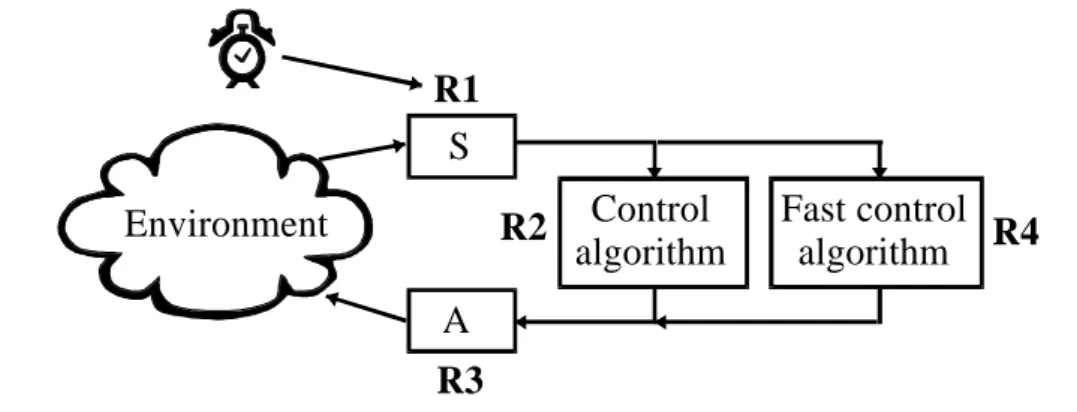
defining an additional rule that is trigged by a transient and executes a faster (and less accurate) algorithm than the ordinary one. In figure 4.3, R4 is trigged by an update as in R2, but with a condition that detects a transient:
R4: ON update (t) IF ABS( t.previous - t ) >= transient THEN call fast_algorithm ( t )
As the delay of R4 (τc2) is shorter than τc the total delay from sensor reading to
Figure 4.3 - An additional rule (R4), trigged by a transient and executes a faster
control algorithm than R2.
This solution implies that we can decide the rule ordering. R4 must trigger before R2 in order to be useful. Even R3 must trigger before R2, otherwise the total delay will increase by τc2.
4.2 Mode Changes for Altering Control System
When control systems are built using a distributed active RTDB there are other database functions that can be used. One of these is the possibility of using mode changes that are available in many databases. This functionality can be used as a way of adapting the control system to changes in the environment as described in the preceding section.
The use of a mode change will give a very fast response to a given event, such as when a dangerous situation is detected. In one step the entire system can exchange all control functions to have a proper behavior in the detected situation, i.e., the mode
S A Control algorithm Fast control algorithm R1 R3 Environment R2 R4
change is propagated and executed on all the other physical nodes in the system before other rules on other nodes are executed.
Using mode changes can also be a simple way of compensating for a broken node in the system. If a rule can detect that a node in the system is not working in a proper way, a mode change can easily alter the system so that the rules on the broken node are distributed on a working node.
4.3 Importance of Rule Ordering
There are several rules used to create the control process, several of them may be on the same physical node. There will however only be one way of information flow through the control process and, thus, there will not be any need for a specific rule ordering.
In contrast, the management control functions requires some consideration. Supervision of the control system may be important but can probably be executed when the system has spare time. It will at least be executed before the next sample interval unless the system suffers from an overload situation. If the supervision function writes a log, the delay to execution of the function can be compensated if the delay is known.
To have the system prepared to the changes within the present sample period in the environment these management control functions must be executed before the basic control functions start to process new information. This may however be a problem as the sensor control function will write its information to the database and, thus, the
information is propagated to the other nodes in the system. This situation can be solved in three ways: (1) the rule for adjusting the control system variables has a higher priority than the propagation of information. (2) we include a check of the condition in the read-sensor rule. (3) we add an extra rule that make a copy of the sensor value written to the database and let the control functions use the timestamp of this new value in the calculation.
The first solution handles the situation of running the rule for detecting a specific condition in the environment before the basic control functions start to handle the new information. There is however a problem if something in the control system environment is to be changed in this sample period, e.g., the control system variables. The values this rule writes to the database must be propagated before the information written by the sensor function. Otherwise, all or some of the control functions in the system use the old control system variables in this sample interval.
In the second solution all the rules that check for specific conditions in the environment must be written into one rule. This also implies that all the extra control functions must be executed at the sensor node.
The third solution implies that an extra database variable must be used, a value that must be propagated via the network to the other nodes. It also implies that priorities of the rules must be used so that the function for detection of the specific condition is executed before the copying of the sensor value. Otherwise the information written by the detection-function is not used until the next sample interval.
There is also the function for compensation for transients in the system. If the two control algorithms, the fast and the ordinary (see section 4.1.3), are at the same node in the control system, priorities must be used. In order to have any effect, the function for detecting a transient and calculating a response must be executed before the ordinary control algorithm.
Distribution of Control Functions
In the preceding chapter the modeling of a control application into active rules were described. The final step of building a distributed control system is the distribution of these active rules to the different nodes in the system. As the control system relies on the database replication functionality there are delays introduced into the system as the data is replicated. The introduced delays are of greatest importance as control systems are sensitive to delays. This chapter describes the consequences of distributing the rules to different nodes. In the section 5.1, considerations of importance when deciding on distribution of active rules will be discussed. Further, in section 5.2, we look at how the random time-delays can be handled by using existing tolerant control algorithms and active rules. Lastly, in chapter 5.3, a discussion is hold on where to distribute the rules when building a control system.
5.1 Issues in Distributing a Control Application
Building a distributed control system with a distributed active RTDB as basis introduces several aspects compared to the development of an ordinary control system. The replication of data between the nodes in the database is handled via a network of some kind. To ensure a given delay for all data replicated in the database, a real-time network must be used. A real-time network is a network with timely and reliable behavior. Even so, it is most unlikely that we get a constant communication delay. The distributed environment of the database implies that several nodes causes network load as all updates in all the nodes are replicated, i.e., there will not be only one node sending information. If the communication goes via a non real-time network such as CSMA-CD, the delays will be even more unpredictable. We assume that the replication delays will have a random distribution. A closer study of how delays in CAN and Ethernet networks are distributed can be found in [Nil98].
Time sensitive functions – The basic control functions are all sensitive to delays
introduced in the system, especially in the case of random delays. This means that the delays must be considered and compensated for in order to deliver a given control performance. The management control functions are not sensitive to the randomness of the delays. It is instead the actual length, i.e., the latency, which is important.
Synchronization of multiple sources of information – A control application where
there are several distributed sensors and actuators implies several different delays (see figure 5.1). We assume that sampling in the sensor nodes are done synchronized and that the information are written directly to the database. The measurements of interest for a given control function arrives at different points in time and, thus, have individual random delays. Normally the computation in the control function cannot start until the information from the sensor with the longest delay has arrived. It might, however, be possible to define a rule that use a certain number of the needed values and infer the others. This rule can either be time-triggered and start the computation at a given point in time or trigger when enough values are present.
Figure 5.1 - Control system with several sensors
Example 11 – Consider the setup in figure 5.1 where we have a system with several
sensors connected to a control algorithm performing calculations. We will have n
delays, τsci, i ∈{1,…, n}. The information from each sensor arrives at different points
the longest has delay has arrived. The calculation of the delays must only be done once as it is assumed that the sensor readings are synchronized.
Total delays – Using information in several steps means that the delay increases in
each one of them. When the delay in the system is to be compensated for, the total delay from the sensor reading to actuator must be used, not only the delays from the previous and next steps in the control process.
Figure 5.2 - Control system with delays
Example 12 – Consider figure 5.2 where the delays are to be compensated for in the
control algorithm. The control system is built with three separate physical nodes where
the estimator and control algorithm are at same physical node. The delays are: τse,
delay from sensor to estimator; τsc, delay form sensor to controller; τec, delay from
estimator; and τca, the delay from algorithm to actuator. We define t as the average
time for replication of information between the nodes. We assume the time for calculation in the estimator and control algorithm are insignificant. We also make the
assumption that τec << τse, τec << τsc and τec << τca since the database update and event detection is done within the node. Consider the case where the delays in the system
S
A
Environment
τ
seτ
ecτ
scτ
caControl
algorithm
Estimator
should be compensated for. Using the delay from previous function in the control process and to the next function in the control process in compensation gives an
average delay of t . The total average delay that affects the system, and that should be
compensated for, is instead 2t (τce+τec+τca ≈2t or τce+τec+τca ≈2t ).
Level of consistency – In this dissertation we consider the consistency that the
database can assure. We will assume three separate levels of consistency, namely: 1. Immediate consistency where data is replicated to all nodes and committed at the
same time in all nodes. To ensure this level of consistency a distributed atomic commitment protocol must be used [Mul94].
2. Eventual consistency where data is replicated at a later point in time, this can
either be done with as soon as possible (ASAP) [Gus95] or within a bounded time [Lun97].
3. No guarantee of consistency is given.
The three levels of consistency involve different time delays, due to control systems sensitiveness to delays the lowest appropriate level of consistency should be used. To ensure the immediate consistency in a database a distributed atomic commitment protocol (DACP) must be used. This protocol has overhead in communication between the nodes in the system and, thus, takes valuable time to execute. In [Mul94, chapter 6] a DACP is described. Under the assumption that the underlying network have a broadcast facility, the DACP involves two sendings of
information from the coordinator, the node where the information is updated, to the participants, the other nodes in the database. The participants each sends one response on the network before the transaction are committed and one more each when
committed. If the time for one transmission on the network is d and n is the number
nodes, there is d (2+(n-1)) time needed for a commit and another d (n-1) before the
protocol has finished. There are also some overhead involved as the protocol is executed in the coordinator and participants.
The second and third levels of consistency both involve a propagation of data using
the broadcast facility of the underlying network, i.e., d of time for delivery. The
second level also involves some overhead in node where the data is propagated, the time for the overhead depends on the algorithm. In [Lun97] a version vector algorithm is described. This algorithm will use n*m*l number of comparisons, where n is the number of nodes, m the number of objects, and l the number of transactions in the log filter, to detect an inconsistency. Only in the case of an inconsistency, a conflict resolution mechanism is executed.
In choosing an appropriate level of consistency in a control system based on a distributed database we must examine if inconsistencies can occur, and if they do, in what situations. Inconsistencies occur when we have a read-conflict or write-write-conflict in the database, i.e., if one or several control functions use and update the same data in the database. First we look at the basic control functions.
All the basic control functions in the control process read and write data in the database. In normal operation of the control system we assume that all control
functions in a control process caused by a sample instant, ht, has been reached before the next sample instant, h(t+1). Each function in a control process receives data from the previous function as the update event of a database variable is detected. The function makes a calculation based on the database variable, and updates another database variable when finished. There will not be any two functions updating the same database variable, and thus, there are no write-write conflicts. There are not any two basic control functions having any dependence between each other that can cause a read-write conflict.
If there is a high load in the system and, thus, the control process has not yet reached the actuator at the time of next sample instant, h(t+1), there might be a problem. This may cause a control function to update the same value as already been updated recently and a queue is therefore needed. If a FIFO queue is used there will still not be any inconsistencies. If such a high load in the system is allowed, the performance may be enhanced by the technique described in [Cha95].
Among the management control functions have supervision function. This function delivers information either to a log, or to a Graphical User Interface (GUI) for presentation of interesting information. However, this function will not write the same information as any other function and, thus, will not cause any conflict.
The control function for adoption of the control process to the present environment can update the control system variables that are used by management control functions. No management control function will make any change to the control system variables, but there may be several rules of this kind that can change the values.
In the case that two or more of these rules are executed concurrently, either on one node or on separate, there may be both read-write conflicts and write-write conflicts.
Functions for handling of exceptions in the environment are not the source of conflicts unless they are executed concurrently and result in contradictory decisions. This must not be allowed.
When transients are to be handled an extra rule is used to shorten the delay from the sensor readings to actuation. Consider the case where only one rule is used for actuation. In this case, both the ordinary control algorithm and the fast control algorithm must write data to the same database variable to have it actuated. This may be a source of a write-write conflict. However, the system will result in an expected behavior. Although the system output is correct if the lowest level of consistency is used, the inconsistent state may not be wanted. To avoid this situation we may instead use two actuation rules, one for the ordinary control algorithm and another for the fast control algorithm. Now there will not be any write-write conflicts.
5.2 Handling Random Time-Delays in System
Using the database replication mechanism for sending information between the different functions in a control system introduces delays. We cannot know the exact delays in advance and, therefore, cannot build a control system using standard control
theory4. Standard control theory implies that we have a constant time delay. What we
4 What we can do if we have a bounded delay, is that we wail until a given deadline is reached (see