School of Innovation, Design and Engineering
BACHELOR THESIS IN
AERONAUTICAL ENGINEERING
15 CREDITS, BASIC LEVEL 300
Development of a new
drawing system for STS
Authors: Mikael Berkelund and Christian Håkonsen Report code: MDH.IDT.FLYG.0189.2008.GN300.15HP.D.
Abstract
An engineering firm which handles and constructs drawings needs well defined routines and structures which should be homogeneous through all the different departments. A common drawing system results in better quality and cooperation between the
departments.
SAS Technical Services (STS) did not have a common drawing system which had led to development of different routines in the different regions and departments. Requested was development of new routines regarding engineering drawings, such as drawing numbering structure, revision and subscription routines, which standards to adhere to, custom made drawing templates and management of the drawings with belonging documents.
Each requested task was broken into minor tasks and analyzed. Solutions by different leading engineering companies were used for comparison and ideas.
All the tasks were collected and organized in one single document which is the result of the thesis; a drawing instruction.
The drawing instruction will after a learning phase ease the work for the STS engineers as all necessary information can be found in one single place. Also, work with contractors will be time-saving as the instruction can be handed out for guidance.
Date: 29 jan 2008
Carried out at: SAS Technical Services Advisor at MDH: Tommy Nygren
Advisor at SAS Technical Services: Anders Pramler Examinator: Gustaf Enebog
Sammanfattning
En ingenjörsfirma som hanterar och skapar mängder med ritningar behöver väldefinierade rutiner och strukturer som är homogena genom hela bolaget. Ett
gemensamt ritningssystem resulterar i bättre kvalitet och bättre samarbete mellan de olika avdelningarna.
SAS Technical Services (STS) hade inte ett gemensamt ritningssystem vilket har lett till att de olika avdelningarna har utvecklat olika rutiner rörande ritningar. Önskemålet var utvecklande av nya rutiner rörande ingenjörsritningar såsom ritningsnumreringsstruktur, revisions- och prenumerationsrutiner, vilka standarder som skall följas, egna
ritningsmallar och skötsel av ritningar med tillhörande dokument.
Varje önskad uppgift blev uppdelad i mindre uppgifter och analyserad. Lösningar från olika ledande ingenjörsbolag användes för jämförelse och idéer.
Alla uppgifterna samlades och organiserades i ett och samma dokument som är resultatet av detta arbete; en ritningsinstruktion.
Ritningsinstruktionen kommer efter en inlärningsfas underlätta arbetet för ingenjörerna på STS eftersom all nödvändig information nu finns på ett och samma ställe. Arbeten med entreprenörer vill också bli underlättande eftersom instruktionen kan delas ut för vägledning.
Index
ABSTRACT ... II INDEX ... IV 1 GENERAL ... 1 1.1BACKGROUND... 1 1.2PURPOSE... 1 1.3GOAL... 1 2 METHODS... 2 2.1FEASIBILITY STUDY... 22.2DRAWING NUMBERING SYSTEM... 4
2.2.1 The old systems ... 4
2.2.2 The new system ... 6
2.3CAD-TEMPLATES... 7
2.4DENOTATIONS OF DRAWING AND PROJECT STATUS... 9
2.5EVALUATION OF STANDARDS... 12
2.6ROUTINES FOR REVISION OF DRAWINGS... 12
2.7ROUTINES FOR SUBSCRIPTION OF DRAWINGS... 13
2.8MANAGEMENT OF CURRENT PAPER DRAWINGS... 13
2.9EVALUATION OF DMS ... 15
2.10REVISION OF ESE AND DOM... 17
3 RESULTS... 18
4 REFERENCES ... 19 APPENDIX ASchedule
APPENDIX BWBS-diagram APPENDIX C List of standards APPENDIX D Workflow charts APPENDIX E Drawing template APPENDIX F Text for DOM APPENDIX G Text for ESE ANNEX STS drawing instruction
1 General
1.1 Background
The project was initiated by SAS Technical Services (STS) Engineering Services (ES) at Stockholm Arlanda airport. STS is an EASA1 Part-145 and Part-21 approved subsidiary of the SAS2 Group which main interest is to provide MRO3 services to SAS Denmark, Norway, Sweden, Spanair and more carriers. The company is Scandinavian and its main bases are located in Stockholm, Copenhagen and Oslo.
ES is a part of STS which functions as an internal consulting firm with their own profit responsibility. With approximately 120 engineers ES is represented at all of the STS bases.
Today STS uses several different drawing systems to construct, number and manage their drawings. Those known to us are:
• A brief description of how to number the drawings and how to fill out the information fields on the drawing sheet in the DOM4.
• An even more brief description on how to number and manage the drawings in the ESE5
• A type-written binder for STS Stockholm from late 1987 which none of the aforementioned systems referrers to and probably few of STS’ engineers know exists.
• Denmark, Norway and Sweden all use different numbering systems.
1.2 Purpose
A redefined and common drawing system for the whole organization (STS) will after a learning phase make all the work regarding drawings in either way more efficient. From a quality assuring point of view a common and well defined system makes less room for error and assures a well structured system.
1.3 Goal
The goal was to make a proposal for a new drawing system by the end of July 2007.
1
European Aviation Safety Agency
2
Scandinavian Airlines System
3
Maintenance, repair and overhaul
4
Design Organization Manual
5
Engineering Services Exposition
2 Methods
2.1 Feasibility study
After the introduction meeting with the supervisor at STS Stockholm it was decided to spend two weeks to familiarize with the material handed out as well as evaluate the current systems and make a preliminary schedule for the work. The scope of work was divided into sub tasks (see appendix B) and estimations were made of the time required by each task to come up with the preliminary schedule (see appendix A).
After reading through the different systems and manuals, the pros and cons of the different systems were listed.
The systems and manuals that were evaluated were: DOM
+ - A standardized drawing template
exists
Lack of information in the title block Easy to read Diffuse references to which standards
that are applicable.
Complex drawing numbering system Lack of information (only 3 pages) Table 1
ESE
+ - Well explained drawing numbering
system
Refers to a drawing system which is not used
Lack of information (only 2 pages) Table 2
The Stockholm binder
+ - Detailed information Almost 20 years old
Covers almost all topics required Hard to read. Complex language. Refers to standards Hard to adapt to present day computer
environment.
Some information and references are obsolete
Table 3
Volvo
+ -
Comprehensive Wrong business
Adaptable to today’s computer environment
Too detailed information
Structured and well-presented Mainly refers to their own standards. In English and Swedish
Table 4 Boeing
+ -
Detailed Probably too comprehensive for an
MRO like STS Easy to understand
Simple but clever solutions
Table 5
2.2 Drawing numbering system
2.2.1 The old systemsTo get a general overview of how the drawings could be numbered evaluations of the current systems together with Volvo and Boeing’s solutions were made. All the STS regions (Sweden, Denmark and Norway) use different numbering structures. Although some local variations in the different regions’ structures occurred, those shown below are the most common ones.
STS Denmark Example: DA400295
Where D is for Denmark, A4 is for the paper size (A4) and 00295 is a sequence number.
The structure is simple and contains too little information. As the drawing number is the same as the part number, it is important that the number contains as much vital information as possible and at the same time is not too long. The information about where the drawing is made and which paper size it has had no greater importance in the drawing number. As long as you can see from the drawing number that the part is up-to-date and is certified for installation, it does not matter which country it comes from. Regarding the paper size it no longer matters to include it in the drawing number as the drawings nowadays exist in digital archives on computers. You no longer have to know which physical archive drawer to look in.
STS Norway Example: 9525686
Where 95 is for engineering drawing, 25 is for the ATA6-chapter and 686 is a sequence number.
The Norwegian number structure also contained too little information but it was a clever idea to include the ATA-chapter. By including the ATA-chapter you get a more organized structure and you can shorten the sequence number.
6
American Transport Association
STS Sweden Example: 25-5701
Where 25 is for the ATA-chapter and 5701 is a sequence number Although the Swedish structure looks more organized than the Norwegian one it mainly contains the same information. More information has to be included.
Boeing
Example: 143N3111
Where 143 is a WBS7-identifier, N is for the aircraft type and 3111 is a sequence number.
The Boeing system is well structured but advanced and hard to read and learn for a person who does not work in Boeing, especially without all the tables that explains the different numbers. To further show the complexity of the system, the aforementioned example (143N3111) can be divided into smaller parts:
1 – Structures design 4 – Body
3 – Section 43 N – Model 757 3 – Skin Panels
1 – Skin panel instl - Crown 11 – An assigned number
The system is too complex to adapt to STS. Volvo
Even though Volvo does not manufacture airplanes, their drawing system is comprehensive, so it was decided to evaluate their numbering system as well. In general their system is not adaptable for the aircraft business but it is interesting that they include the current project status for their items in the CAD8 filename. It is as mentioned earlier important to see which phase a drawing/part is in, so the decision was to
implement it in the new drawing number.
7
Work break-down structure
8
Computer Aided Design
2.2.2 The new system
The proposal for a new numbering system builds on evaluations of the aforementioned systems (section 2.2.1) and recommendations from the supervisor at STS.
The following positive observations from the evaluated systems will be included in the new numbering system:
• ATA-chapter • Project status • Revision status
As already mentioned it is important to know if a part is up-to-date. Even if the part belongs to the current phase (project status), it is important to know if it is of the latest revision. Therefore the revision status also is to be included in the proposal.
The proposal for a new numbering system is in the format: AABBB-CCCC-D.D Where: AA – ATA-chapter BBB – Project status CCCC – Sequential number D.D – Revision status
For a more detailed description see 3.2.2 in the drawing instruction (annex).
2.3 CAD-templates
Because all the departments were using different templates one assignment was to come up with new common templates that should be used by all the
departments within STS in the future.
The new STS CAD-templates are based on comparing the different
departments’ current CAD-templates and by talking to the supervisor at STS about the design and relevant information for the CAD-template.
The discussions with the supervisor at STS resulted in a list with major and minor relevant information to be included in the template:
Major relevant information for STS is: • Tolerance • Projection method • Designed by • Checked by • Approved by • Date of design • ATA-chapter • Aircraft type • Drawing number • Project status
Minor relevant information or STS is: • Region/Department • Description • Sheet number • Scale • Supersedes • Superseded by • Reference drawing • Order number • Drawing order from
• Approved engineering department • Surface finish
• Next assembly
The evaluation of the different drawing templates used by the following Regions/Departments in STS:
STS Denmark
+ - Simple but informative part list No information on:
• Projection method • Paper size • Aircraft type • Tolerance • Sheet number • Project status
Pretty much uniform title blocks No revisions list on the old drawings
Table 6 STS Norway
+ - Comprehensive title block
information
No information on: • Project status • Sheet number
Informative revision list Too much information of less importance
Strange indication of paper size Table 7
STS Sweden
+ - Simple but informative part list No information on:
• ATA-chapter • Projection method • Tolerance
• Aircraft type • Project status Informative revision list
Clear date indication
Table 8
Conclusion
The template was to be as clean as possible and at the same time contain all relevant information. For example it was decided to put the information “supersedes/superseded by” in the revision list as it is not that often a drawing replaces another one.
The information “next assembly” is excluded because there is no interest in tracking upwards in the system. It is more important to track sub-ordinate documents.
Some items which are in the minor relevant information list are still included in the new CAD-template as they complement major relevant information. The items are as follows:
• Region/Department • Description
• Sheet number • Scale.
After analyzing the pros and cons, together with the list of relevant information above, a proposal for new CAD-templates for STS was developed. The proposal consists of CAD-templates in the format A0, A1, A2, A3 and A4 based upon existing ISO9-templates that are modified to fit STS requirements.
For the result see appendix E (A4 version).
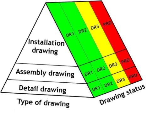
2.4 Denotations of drawing and project status
Denotations of drawing and project status are important if you want to trace the drawing. If a drawing is in a design phase it is important to see that it is a drawing under development and not a production drawing. A new denotation system that shows both drawing and project status had to be developed. Some companies’ different denotation systems were checked and compared to develop a new system. The companies that were compared were STS and Volvo.
STS
The old system used in STS was based on that a drawing could be in status DR110, DR2 and DR3. These denotations for the drawing status were not shown in the title block of the drawing but they all represented different levels.
9
International Organization for Standardization
10
Design review 1, 2, 3
The following is an extraction from the STS DOM rev.4 explaining the meaning of DR1, DR2 and DR3.
Phase Description Purpose Scope
DR1 Feasibility study To ensure that the
organization is capable to meet the customer request.
Verify if the change is within the terms of approval. Reference: DOM 1.4 “Scope of Work” Identify data requirements. Identify the required and available resources to perform the task.
Perform a pre-classification of the change. Use DOM 3.2.3.4 “Classification of Changes” as a guideline.
DR2 Preliminary design review
To ensure that all conditions are met to complete the design in accordance with this manual and the work order (customer specification).
Check if the customer specification is complete. Establish a common
understanding of the customer specification (customer
involvement is recommended). Check if required data is available.
DR3 Critical design review
To establish design solution and obtain final acceptance of the design from the customer prior to completion of the type investigation program (TIP) and production of parts.
Present solution to customer and obtain acceptance.
Note: At this stage, it is important to emphasize to the customer that after completing the critical design review, any change to the specification will most likely lead to a
re-evaluation of the design. This might require more time and resources in the design process. Table 9
Volvo
Volvo has another type of denotation system. They have a number representing the change condition (i.e. 08 represents change number 8). If the drawing is ready for construction the letter “P” (Production) is placed before the change condition number.
Conclusion
The new system that was developed is based on STS’ existing system. The phases DR1, DR2 and DR3 are maintained, but one more phase was added, the “PRD” phase. The new phase states that the drawing has reached a point of no return. After that there shall not be any changes to the drawing except for revisions. The drawing is in “Production”.
2.5 Evaluation of standards
The Stockholm manual included all the standards referred to in the manual together with a list of all of them named “Abonnemangsklass 3400, Ritning och toleranser”. All of the standards were in paper format and some were dated from the 1960s.
As the new drawing instruction was to be digital, the standards also had to be in digital format. By searching the internet for digital versions of the standards in the list, it became obvious that many of them were obsolete. SIS11 was
contacted to find out if the old list (Abonnemangsklass 3400) had been revised or replaced. No such list existed anymore. Each standard was manually looked up on SIS’ website in search for a replacement standard. The results were collected in an excel document (see appendix C).
As STS buys their standards from IHS12 their catalogue was browsed via the SAS intranet to confirm whether some of the updated standards already were in possession of STS. None of the standards needed to make the new drawing system were in possession. As SIS mostly presented Swedish versions of the ISO standards, IHS also possessed the English/international versions. It was decided to go for the international standards where possible as the instruction is aimed at Denmark, Norway and Sweden and STS may have international customers who may want to take a look at the instruction together with the standards. The excel-document was updated to match IHS’ standard versions and handed over to the supervisor as a proposal for a purchase.
Conclusion
Since it was too expensive to carry out the proposal of buying new standards a new suggestion/routine was established together with the supervisor. STS shall maintain their old standards and successively upgrade the standards as required. For a complete list of old and new recommended standards see appendix C.
2.6 Routines for revision of drawings
Routines for revision of the drawings need to exist to assure that everybody works with the latest version.
STS had no standardized routines for revision of drawings. Engineers were interviewed to get a good view of the problem. Some engineers did not know the routines and different versions were told from different engineers. There are many ways of showing revision status on the drawing and in the drawing number. You can use letters or numbers, or a combination of these.
11
Standardiseringskommissionen i Sverige
12
Information Handling Services
Conclusion
Schematic workflow charts were developed for the new routines for revision of drawings.
See appendix D for the workflow charts.
It was decided to mark the revisions in numbers. The reason that it was chosen to have numbers instead of letters is because it was decided to use minor and major revisions. The proposal is in the form of X.Y, where X is for the major revision status and Y is for the minor revision status.
For further info see section 3.3.2 in the drawing instruction.
2.7 Routines for subscription of drawings
The meaning of a subscription to a drawing is that all the users of a specific drawing can be assured that they work with the latest revision of the drawing. This can either be done manually or automatically. A manually example could be that all the users involved in a drawing are to be noted in an excel-document in connection with the drawing number. When somebody revises the drawing, he or she has to notify the other persons, preferably by e-mail. This method may work perfectly for small projects but in big companies like STS with multiple projects, this method may be unreliable and time demanding. Automated systems were evaluated and such a service is often included in a DMS13. This means that all the persons who have a copy of a specific drawing will get a notification whenever the drawing is revised or even when work is in progress. Our proposal for subscription to drawings will be described together with our DMS suggestions (see section 2.9).
2.8 Management of current paper drawings
As STS has existed since the pre-CAD era, large archives of paper drawings have been built up. To save space and to prevent deterioration of the paper drawings the most obvious solution was to convert them to digital pdf14-files by scanning. Before proposing this method, the amount of work combined with scanning such a large number of drawings had to be taken in consideration. Investigations resulted in a confirmation that STS Oslo already had scanned their old drawings. After a positive response from the supervisor, it was decided to go ahead and recommend STS to apply this scanning solution. To reduce the workload of the digitalization process, STS were recommended to keep the old drawing number for the paper drawings instead of renaming them according to the new numbering system after scanning.
When evaluating different types of DMS’ (see section 2.9) an alternative solution which is called raster to vector conversion was discovered. This method converts paper drawings into editable CAD-files on the computer.
13
Document Management System
14
Portable Document Format
Although it is outside the scope to evaluate raster to vector conversion
programs, it was found interesting and STS were recommended to take a closer look at this solution when they have decided which DMS to use.
2.9 Evaluation of DMS
When having to manage all the drawings and other documents that STS has there can be complications because of the amount of documents. A DMS results in more reliable and safer handling of the documents. Today STS possess a DMS named Soludyne which is evaluated for replacement.The task was not to make a proposal for one specific DMS because of the amount of work and time it takes to evaluate several DMS’. This was not in the scope of the bachelor thesis.
After surfing the internet and talking to several companies and the supervisor at STS these three alternatives were evaluated:
• Autodesk Productstream • Trix Organizer
• Synergis Adept
The hardest part was to get information on these DMS’ but after many phone calls and e-mails some information was obtained. The information varies from questions answered on e-mail to obtained commercial brochures.
Based on the information collected each different DMS was compared against the demands, which were:
The system shall:
• Be fully compatible with AutoCAD.
• Be able to search for information in the drawing title block.
• Be able to get and reserve drawing numbers from a database i.e. word document or similar.
• Maintain a register of which person(s) that possess copies of the drawing.
• Notify possessors of copies that are revised.
• Be able to work in big networks (drawings or similar can be picked from computers in the whole SAS).
• Be easy to use, quick learning process. • Be easily adaptable.
Secondary requirements: • Demonstration on-site. • Education on-site.
• Possibility of getting a demo-version of the program.
The comparison is between Autodesk Productstream, Trix Organizer and Synergis Adept.
DMS
Demand Trix Organizer Synergis Adept Autodesk Productstream
AutoCAD compatibility Yes Yes Yes
Title block attribute extraction
Yes Yes Yes Pick and reserve
drawing number/project number from database
Yes N/A* N/A
Keep track of drawing possessors
Yes Yes N/A Subscription
(if drawing is revised possessor shall be notified) Yes (automatically when drawing is revised) Yes Yes (automatic ECO15) Ability to work in big
networks
Yes Yes Yes
Easy to use N/A Yes N/A
Demonstration of the program Yes (in Gothenburg) Yes (video demonstration via internet) N/A Demo-version No No (pilot program for 60 days) N/A
Training at STS Yes Yes
(many options)
N/A
Multiuser management No No Yes
Customizable Yes (together with Trix) N/A N/A Cost Varying (depending on the modules) Valuable N/A
*The information was not possible to extract from our recourses.
Table 10
As shown in the table above all of the DMS’ could be used by STS. In addition all the programs are over-qualified for the tasks that STS wants.
An important note is that the evaluations are only based on information from the manufacturers’ websites, brochures, and e-mail and phone conversations with the manufacturers. Due to the size and complexity of DMS’ it was not possible for the manufacturers to send demo copies. One manufacturer offered a live demo on their site and another manufacturer offered a 60 day pilot program but due to lack of recourses these offers had to be declined.
15
Engineering Change Order
2.10 Revision of ESE and DOM
As both the ESE and DOM currently contain information on construction of drawings, parts of both documents had to be updated. As the ESE and DOM already are large manuals it was decided to keep text as short as possible. This was accomplished by mainly referring to the drawing instruction where
possible, which also makes the revising of the drawing instruction easier as text only has to be changed at one place.
Where no change to the current text was made, it is denoted as “Unchanged”. It was decided to not include the current ESE and DOM text to reduce the number of appendixes in this report and because it is of no importance for the thesis. For the updates see appendix E and F.
3 Results
The main result of this thesis is the new drawing instruction which is included as an annex (see annex). The sub-results which together build up the instruction are presented under their respective method in the previous section (section 2) and most of them will also be found in the new drawing instruction.
4 References
Boeing, no date. Boeing drawing course.
Hansson, Pål, Karlsson, Göran & Pärletun, Lars Göran, 2002. Kom igång med AutoCAD
LT2002. Studentlitteratur AB
Scandinavian Airlines System,1987. Ritningsinstruktion. Stockholm Arlanda. Tonnquist, Bo, 2005. Projektledning. Stockholm: Bonnier Utbildning AB Volvo, 1998. Volvo Corporate Standards’ CD-ROM 1998.
Volvo, 1999. Volvo Corporate Standards’ CD-ROM 1999.
Appendix A
ScheduleAppendix B
WBS-diagramAppendix C
List of standardsOld standard New standard
Number Name Published Number Name Published
SS 1900
Ritningsregler - Ritningar och andra produkthandlingar -
Terminologi 1983-04-01 SS 1900-1
Ritningar och andra produkthandlingar - Terminologi - Del 1: Beskrivande dokument. 1995-11-30 SS-ISO 6428 Ritningsregler - Fordringar för mikrofilmning - Allmänna ritningsprinciper 1984-06-25 SS-ISO 6428 Utgåva 2 Ritningsregler -Fordringar för mikrofilmning - Allmänna ritningsprinciper 1993-09-30 SS-ISO 5457 Ritningsregler -
Storlekar och utformning
av ritningsblanketter 1983-04-01 SS-EN ISO 5457 Ritningsregler - Storlekar och utformning av ritningsblanketter (ISO 5457:1999) 1999-04-23 SMS 1905 Ritningsregler - Textning 1975-09-15 SS-EN ISO 3098-4 Teknisk produktdokumentation - Textning - Del 4: Diakritiska och speciella tecken för det latinska alfabetet (ISO
3098-4;2000) 2000-07-28
SS-ISO 128
Ritningsregler - Linjer, vyer, snitt och särskilda
markeringar 1983-04-01
SS-ISO 128-20
Ritregler - Allmänna regler - Del 20: Linjer -
Grundläggande krav. 1996-12-13 SS-ISO 5455 Ritningsregler - Skalor 1983-04-01
SS-ISO 5455 Utgåva 3 1993-07-30 SS-ISO 129 Ritningsregler - Måttsättning - Allmänna principer, definitioner, metoder för utförande och särskilda markeringar 1986-04-01 SS-ISO 129-1:2004 Ritregler - Angivning av mått och toleranser - Del 1: Allmänna principer (ISO
129-1:2004, IDT) 2004-11-08 SS-ISO 6410 Ritningsregler - Ritning av gängade objekt 1983-04-01 SS-ISO 6410-1 Ritningsregler - Gängor och gängade objekt - Del
1: Allmänna principer 1993-10-29 SMS 2536 Ritningsregler - Förenklad ritning av gänginsatser 1968-12-20 SS-ISO 6410-2 Ritningsregler - Gängor och gängade objekt - Del
2: Gänginsatser 1993-10-29 SMS 2537 Ritningsregler - Förenklad ritning av fjädrar 1975-01-01 SS-ISO 2162-1 SVENSK STANDARD Fjädrar - Del 1: Förenklad
ritning 1994-05-20 SMS 2538 Ritningsregler - Förenklad ritning av rullningslager 1968-12-20 SS-ISO 8826-1 Ritningsregler - Rullningslager - Del 1:
Allmän förenklad ritning 1991-06-04
SMS 2539 Ritningsregler - Förenklad ritning av tätningsringar 1968-12-20 SS-ISO 9222-1 Utgåva 2 Ritningsregler -
Dynamiska tätningar - Del 1: Allmän förenklad
ritning 1993-07-30
SMS 2540
Ritningsregler - Förenklad ritning av
bomaxlar och bomnav 1968-12-20 SS-ISO 6413
Ritningsregler - Ritning av
splines och serrationer 1992-06-03
SMS 2541 Ritningsregler - Förenklad ritning av kugghjul o d 1975-01-01 SS-EN ISO 2203 Ritregler - Förenklad ritning av kugghjul (ISO
2203:1973) 1997-12-30 SS-ISO 6411 Ritningsregler - Förenklad ritning av dubbhål 1983-06-25 SS-ISO 6411 Utgåva 2 Ritningsregler - Förenklad ritning av dubbhål 1993-07-30 SS-ISO 5261 Ritningsregler - Byggnadskonstruktioner av metall 1983-06-25 SS-ISO 5261 Utgåva 2 Ritregler - Förenklad ritning och måttsättning av rör och stänger i
konstruktioner. 1995-11-24
SMS 485
Ritningsregler - Dimensionstoleranser
och passningar. Skrivsätt 1963-01-15
SS-ISO 406 Utgåva 1 Ritningsregler - Toleranssättning av längdmått och vinkelmått 1989-09-13 SS 672 E Ritningsregler - Ytjämnhetsuppgifter 1981-05-20 SS-EN ISO 1302 Utgåva 1 Geometriska produktspecifikationer (GPS) - Metod att ange ytstruktur i teknisk produktdokumentation (ISO 1302:2002) 2002-03-01 SS 665 Ritningar - Svetsbeteckningar - Register, definitioner och allmänna upplysningar 1988-01-27 SS-EN 22553 Utgåva 1
Ritningsregler - Svets- och lödförband - Beteckningar på ritningar 1994-09-17 SS 666 Ritningar - Svetsbeteckningar - Smältsvetsar 1988-01-27 SS-EN 22553 Utgåva 1
Ritningsregler - Svets- och lödförband - Beteckningar på ritningar 1994-09-17 SS 667 Ritningar - Svetsbeteckningar - Motståndssvetsar 1988-01-27 SS-EN 22553 Utgåva 1
Ritningsregler - Svets- och lödförband - Beteckningar på ritningar 1994-09-17 SS 2772 Ritningsregler - Svetsbeteckningar 1985-11-15 SS-EN 22553 Utgåva 1
Ritningsregler - Svets- och lödförband - Beteckningar på ritningar 1994-09-17 SS 2773 Ritningsregler - Svetsar - Måttsättning av fogar 1985-11-15 SS 2773 Utgåva 3 Ritregler - Svetsförband - Måttsättning av fogar 1995-03-08 SS ISO 4063 Ritningsregler - Sifferbeteckningar för
svets- och lödmetoder 1980-01-01
SS-EN ISO 4063 Utgåva 1
Ritningsregler - Sifferbeteckningar för svets- och lödmetoder
(ISO 4063:1998) 2000-08-25 SS 2775 Ritningsregler - Måttsättning av konor 1978-07-01 SS-ISO 3040 Utgåva 1 Ritningsregler - Konor - Angivning av mått och toleranser 1992-06-03 SS 1918 Ritningsregler - Måttsättning av ytbelagda objekt 1979-04-02 Does not exist SMS 677 ISO-toleranser - Urval av hål- och axeltoleranser för allmänna ändamål 1971-12-31 SS 677
ISO tolerans- och
passningssystem - Urval av hål- och axeltoleranser för allmänna ändamål 1990-09-12 SMS 2190 ISO-toleranser. Urval av hål- och axeltoleranser för kontorsmaskiner 1965-11-01 Does not exist SMS 507 ISO-toleranser - Urval
av passningar. Hålet bas 1967-03-15 SS 507
ISO tolerans- och
passningssystem - Urval av
passningar - Hålet bas 1990-09-12
SMS 508
ISO-toleranser - Urval
av passningar. Axeln bas 1967-03-15 SS 508
ISO tolerans- och
passningssystem - Urval av
passningar - Axel bas 1990-09-12
SMS 723
Toleranser - Tillåtna måttavvikelser när tolerans ej direkt utsatts. Smältsvetsade konstruktioner. Metalliska material 1973-03-31 SS-EN ISO 13920 Svetsning - Allmänna toleranser för svetsade konstruktioner -Dimensioner för längder och vinklar - Form och
läge (ISO 13 920:1996) 1996-12-13
SMS 715
Toleranser - Tillåtna måttavvikelser när tolerans ej direkt utsatts. Bearbetade detaljer. Metalliska materia 1968-07-15 SS-ISO 2768-1 Toleranser - Generella toleranser - Del 1: Toleranser för linjära mått och vinkelmått utan direkta
toleransangivelser 1990-10-17
SS-ISO 1101
Form- och lägetoleranser - Allmänt, definitioner, symboler, ritningsangivning 1984-11-15 SS-ISO 1101:2005 Geometriska produkspecifikationer (GPS) - Geometriska toleranser - Form- och
lägetoleranser 2005-06-07
SS-ISO 7083
Form- och lägetoleranser - Proportioner och mått
för symboler 1984-11-15
Does not
exist SS-ISO 5459
Form- och lägetoleranser - Referenser och referenssystem 1984-11-15 Does not exist SMS 1921 Toleranser - Måttjämkning 1961-12-15 SS-EN ISO 2692:2007 Geometriska produktspecifikationer (GPS) - Form- och lägetoleranser - Max materialmått (MMR), min materialmått (LMR) och reciprocitet (RPR) (ISO 2692:2006) 2007-02-05 SMS 673 Ytjämnhet - Ytjämnhetskriterier. Standardvärden. Referenslängder och gränsvåglängder 1987-12-02 SS-ISO 468 Ytjämnhet - Parametrar, värden för dessa samt allmänna reglervid kravspecificering 1987-12-02 SMS 674 Ytjämnhet - Riktlinjer för ytjämnhetsbestämning 1975-11-15 SS 674 Ytjämnhet - Riktlinjer för ytjämnhetsbestämning 1989-10-18 C 3
Appendix D
Workflow chartsAppendix E
Drawing templateAppendix F
Text for DOMThis is the new and revised text for the DOM. The headlines are the correct headlines that are used in the DOM.
3.5 Drawing Standards
EASA Part-21 referencesUnchanged. Purpose Unchanged. Responsibility Unchanged. Document management
See STS Drawing Instruction (SDI) item 3.4 Drawing management. Drawing layout
• Company CAD-templates in format A4-A0 found at location XXX shall be used. • Design/drafting standards, symbology and tolerances must conform to those
standards referred to in the SDI. For a complete list see Appendix B in the SDI. For further information see SDI item 4 Drawing rules.
Drawing identification
• Drawing number structure: See SDI item 3.2.2 Drawing number • The drawing file name is the same as the drawing number
• When a drawing has several sheets, all belonging sheets shall share the same drawing number. The sheets are distinguished by the “sheet field” in the title block.
• Revision status: See SDI item 3.3.2 Revision denotation • Only entire drawings, not separate sheets are revised. Filling out the fields
See SDI item 3.2.4 Title block. Part identification
Unchanged.
Appendix G
Text for ESEThis is the new and revised text for the ESE. The headlines are the correct headlines that are used in the ESE.
7.2.5.7 Drawing control system
GeneralIn order to control drawings issued by STS Engineering Services, a drawing control system has been established containing a numbering system, a registration system, and a classification system.
Drawing number system
See STS Drawing Instruction (SDI) item 3.2.2 Drawing number.
Note: On some older drawings a “/A”, “/B”, “/C” or “/1”, “/2”, “/3” is used to indicate revision status.
Drawing classification Unchanged.
Annex
STS drawing instructionNew drawing instruction for STS
Final version 10sep2007
By Mikael Berkelund and Christian Håkonsen
0 NOMENCLATURE ... 4 1 INTRODUCTION ... 5 2 THE DRAWING INSTRUCTION’S STRUCTURE ... 6
2.1THE DRAWING SYSTEM... 6 2.2DRAWING RULES... 6
3 DRAWING SYSTEM ... 8
3.1DRAWING SYSTEM STRUCTURE... 8 3.1.1 Work Order ... 10 3.1.2 Drawing system documents... 10
3.1.2.1 Installation drawing... 10 3.1.2.2 Assembly drawing... 11 3.1.2.3 Sub assembly... 11 3.1.2.4 Detail drawing... 12 3.1.2.5 Complementary documents... 12 3.1.2.6 Other documents ... 13
3.1.3 Deviation from the drawing system... 14 3.2TEXT ON DRAWINGS... 15 3.2.1 Text... 15 3.2.2 Drawing number ... 15
3.2.2.1 Drawings consisting of one sheet ... 16 3.2.2.2 Drawings consisting of more than one sheet ... 16
3.2.3 Part list ... 17 3.2.3.1 Detail drawing... 18 3.2.3.2 Variation drawing... 19 3.2.3.3 Assembly drawing... 21 3.2.4 Title block ... 21 3.3REVISION OF DRAWING... 24 3.3.1 Execution of the revision... 24
3.3.1.1 Minor revision... 24 3.3.1.2 Major revision ... 25 3.3.1.3 Actions due to revision... 25 3.3.1.4 Drawing Change Notice ... 29
3.3.2 Revision denotation... 30 3.3.3 Revision list... 31 3.4DRAWING MANAGEMENT... 32 3.4.1 Archiving of original drawings ... 32 3.4.2 Backup ... 32 3.4.3 Copying ... 32 3.4.4 Registration of copies... 33 3.4.5 Folding of copies... 33 3.5SECRECY REGULATIONS... 35 4 DRAWING RULES... 36 4.1GENERAL... 36 4.1.1 Information ... 36 4.1.2 Finished state ... 36 4.1.3 Measure units... 36 4.1.4 Decimal character ... 36 4.2DRAWING SHEETS... 37 4.2.1 Format ... 37 4.2.2 Design ... 37 4.3SCALES... 37 4.4TEXT... 37 4.5ITEM REFERENCES... 38 2
4.5.1 Dimensioned assembly drawing... 38 4.5.2 Rivets and bolts ... 38 4.6GENERAL PRINCIPLES OF PRESENTATION... 40 4.6.1 Views... 40 4.6.2 Location of main view ... 40 4.6.3 Lines... 40 4.6.4 Sections ... 41 4.6.5 Other conventions ... 42 4.7DRAWING OF MACHINE COMPONENTS... 42
4.7.1 Conventional representation of threaded parts ... 42 4.7.2 Simplified representation of bolt threads inserts ... 42 4.7.3 Representation of springs... 42 4.7.4 Simplified representation of rolling bearings ... 42 4.7.5 Simplified representation of sealing rings ... 43 4.7.6 Simplified representation of splines ... 43 4.7.7 Conventional representation of gears ... 43 4.7.8 Simplified representation of center holes... 43 4.8DIMENSIONING... 43 4.8.1 General principles ... 44 4.8.2 Sheet metal, bars and assembled elements... 44 4.8.3 Coated parts... 45 4.8.4 Dimensioning and tolerancing cones... 45 4.9TOLERANCES FOR LINEAR SIZES... 45 4.9.1 Terminology ... 45 4.9.2 Permissible deviations for dimensions without indication of tolerances ... 45
4.9.2.1 Fuse welded constructions. Metallic materials ... 45 4.9.2.2 Worked up parts. Metallic materials... 45
4.9.3 Typing ... 46 4.9.4 Selection of tolerances ... 46 4.10SHAPE AND POSITION TOLERANCES... 46 4.10.1 Generalities, definitions, symbols, indications on drawings... 46 4.10.2 Datums and datum-systems for geometrical tolerances... 46 4.10.3 Proportions and dimensions for symbols ... 47 4.11DIMENSION ADJUSTMENT... 47 4.12SURFACE ROUGHNESS... 47 4.12.1 Drawing rules ... 47 4.12.2 Surface roughness values... 47 4.13WELDS – SYMBOLIC REPRESENTATION ON DRAWINGS... 48 4.14OTHER STANDARDS CONSIDERING DRAWINGS AND TOLERANCES... 48
5 COPIES OF THE DRAWING INSTRUCTION ... 49 6 REVISION OF THE DRAWING INSTRUCTION ... 50 7 REVISION SYMBOLS... 51 8 TERMINOLOGY... 52 APPENDIX A ... 53 APPENDIX B... 54
0 Nomenclature
ATA – Air Transport Association CAD – Computer Aided Design DCN – Drawing Change Notice DMS- Document Management System DOM – Design Organization Manual DR – Design Review (i.e. DR1, DR2 etc.) EASA – European Aviation Safety Agency ECP – Engineering Change Proposal ES – Engineering Services
IHS – Information Handling Services
ISO – International organization for standardization MMM – Material and Methods Manual
PRD – Production
PDM – Product Delivery Manager PM – Project Manager
RMC – Raw Material Catalog
SMS – Svensk mekanstandardisering SS – Svensk Standard
STS – SAS Technical Services
1 Introduction
This drawing instruction is of STS’ property and should be implemented for all drawings and belonging documents which STS or an external supplier prepares on STS' drawing sheets.
All personnel who draws, checks or approves drawings should be well known with this instruction and apply it as required.
A basic condition for this instruction to be applied is that all rules are clearly and unambiguously defined. The purpose of this drawing instruction is to define these rules.
In Scandinavian workshop industry, standardized drawing rules developed and continuously revised by ISO are applied. This contributes to make the drawing rules to an international language for technicians and engineers in all countries which apply these standards.
2 The drawing instruction’s structure
The drawing instruction consists of two main parts: - The drawing system
- The drawing rules
2.1 The drawing system
The drawing system includes instructions on how to number the drawing, revise the drawing, filling out the title block on the drawing etc.
2.2 Drawing rules
The drawing rules gives instructions on how the construction of the drawing itself, measurements etc. should be done correctly.
The rules are primarily based on ISO standards although some exceptions occur. For a detailed list of the standards included in this instruction, see appendix A. Drawings made by STS are normally not used in relation to production in large series but moreover for reparations, modifications etc. of aircrafts. The drawings can therefore be expected to be used in limited occasions and it is not normally motivated to spend as much time on these drawings.
A basic demand for every drawing is to unambiguously define the detail or the product with regards to design and function. This demand should never be ignored. On the other side a drawing can be more or less hard to read. To minimize the total workload for certain work within STS, it is often motivated that the belonging drawings can be constructed in a simplified way with regards to the standards.
Regarding how simplified the drawing is to be, unambiguously rules are required. To which extent the drawing is to be simplified depends on which connection the drawing is to be used in.
The drawing instruction regarding the drawing rules is constructed by the following:
- Where possible, references to the valid standards together with information on deviations from the standards are given.
- A complete list of all standards STS possesses and subscribes to are given in appendix A
- Where no standard is applicable, the rules are based on STS customs.
3 Drawing system
3.1 Drawing system structure
The structure for the drawing system mainly consists of drawings together with other documents who together define the finished work.
Figure 1 shows the structure of the drawing system and figure 2 shows the workflow chart.
The figure shows on which level every document is being found in the system. It is just the structure of the system that is shown in the figure. In reality some documents are omitted and some are added.
Figure 1
Figure 2
3.1.1 Work Order
Before a drawing can be made there need to be a work order or a request for quotation from a customer.
3.1.2 Drawing system documents
If there are too many section views or other objects on the drawing so no more available space is left, the drawing shall consist of multiple sheets.
3.1.2.1 Installation drawing
Under a top installation drawing there can be one or more
installation drawings where it is shown how one or more products are being installed in a superior product, (i.e. installation of a chair in an aircraft). Necessary dimensions for the installation shall be placed on the drawing. The exact location of an item shall, if possible, be shown in an isometric view. If possible, the isometric view should be placed in the upper right corner on the drawing. A part of the aircraft shall be visible on the drawing, so dimensions can be given to a certain station on the aircraft. These stations are situated at the frames in the fuselage and at the ribs in the wings and rudder, and can be found on the aircraft supplier’s frame drawing.
Necessary items and other information regarding the work order shall be specified in the part list or in a note on the installation drawing. If specified in a note, the note shall be placed between the revision list and the title block if possible.
The item(s) which shall be installed are defined by one or more assembly drawings.
Complementary documents are given in special notes. In a simple connection, a single written instruction on the assembly drawing or on a separate document can replace the installation drawing. For the later case, the instruction shall be given a drawing number. An instruction of that type can eventually be included in a work order at which no further documentation is needed.
A freestanding product which is not installed in a superior item has no special installation drawing. In this case there is an
assembly drawing on top of the drawing system instead of an installation drawing.
3.1.2.2 Assembly drawing
The positions and assemblies of the parts for a construction are shown in one or more assembly drawings. Necessary dimensions are placed on the drawing.
In an applicable manner this is specified on the assembly drawing part list:
- Necessary sub assemblies. - Necessary detail drawings.
- Necessary items(i.e. rivet, hydraulic engine, glue, color etc.). If possible, RMC-number is used.
Complementary documents are stated in a separate note (i.e. assembly directives).
3.1.2.3 Sub assembly
A sub assembly corresponds to an assembly. Under a sub
assembly there can be further sub assemblies, detail drawings etc.
3.1.2.4 Detail drawing
Detail drawings show a finished detail, i.e.:
- A detail (i.e. engine cowl) which is worked up from a material (i.e. glass fiber laminate) which is made from a goods (i.e. glass fiber carpet) according to the material drawing/MMM.
- A detail (i.e. axel) which is worked up from an item (i.e. aluminum bar). The work can be specified in a special construction instruction.
- A detail made by adjusting an item (i.e. cutting of bolt to gain the right length).
All necessary dimensions and notes for construction are placed on the detail drawing.
3.1.2.5 Complementary documents
Complementary documents could be of two types:
a) Special documents which are developed (i.e. assembly instruction, drawing of a special tool, instructions for a function check or measuring etc.). In that case the document is given its own drawing number. On the complementary document it is stated which main documents that are complemented.
b) Generally concerned standards by different kinds. Within STS there shall be, if possible, an MMM-instruction. References to the complementary documents shall take place in a separate note on the main document.
3.1.2.6 Other documents
A register containing the RMC-number and the MMM-instruction is not really a part of the drawing system, but it shall be used as a reference. If an item that is used on the drawing does not exist in abovementioned registers the item shall have some kind of equivalent documentation (MOVEX registration number, Type Certificate Holder part number or manufacturer’s part number).
- Drawing of bought product
STS can "cut and paste" a drawing of a bought product in the companies own drawing template. This can be useful if the manufacturer changes or discard the design of the product. STS may buy a similar product and then change it according to the drawing that STS possesses. This is done because it is very important and timesaving (certifying of new products) to have exactly the same parts in the aircraft. This product is then given a new part number according to STS standards.
- Arrangement drawing
An arrangement drawing is established when a buyer requests it. The existence of this type of drawing is not common within STS. The arrangement drawing shows the main dimensions which define the amount of space
required for the installation of an item and required connections (i.e. water, electricity and pressurized air etc.).
3.1.3 Deviation from the drawing system
All drawings shall be divided in separate documents according to item 3.1.2. The following exceptions can be made:
- Complementary documents (simple instructions for installation and dimensions etc.) are not necessarily needed to be established. They can be inserted in the main document if it does not affect the document’s readability.
- If the information of a belonging document is included in the main document, the document can be excluded if:
Dimensioning of detail(s) can be made on the assembly drawing or sub-assembly drawing where the detail(s) is included. Either by dimensioning the detail(s) in a section view or another view which refers to the complete item, or by drawing the detail(s) separately on the assembly
drawing.
This method to reduce the amount of documents shall be used thoughtfully. A basic rule is to avoid unnecessary drawing work without making it complex for the workshop. Another basic rule is that dimensioning of a detail on an assembly drawing can be possible if it is the same person that will construct and assemble the detail.
- Items that are put into storage and spare-parts need to have separate documents.
3.2 Text on drawings
3.2.1 Text
When the space in the applicable text field is insufficient, the text shall be placed in the drawing field together with a flag note (where n is an extendable number). A corresponding flag note shall be placed in the actual text field.
Notes and task descriptions are preferably placed between the revision list and the part list to the right in the drawing. If not possible, the notes and sequence of work should be placed on separate sheet(s).
3.2.2 Drawing number
Every original drawing is provided with a unique drawing number. The drawing can eventually contain more than one sheet.
The drawing number shall be given according to the following structure: AABBB-CCCC-D.D.dwg
Where:
AA: ATA-chapter (see appendix A). BBB: Project status (se chart 1 below). CCCC: Sequential number.
D.D: Revision status (see section 3.3.2). Chart 1:
Symbol Explanation Status
DR1 Design review 1 Under development DR2 Design review 2 Under development
DR3 Design review 3 Final stage before construction
PRD Production Production
For further explanations see 3.2.4.2 in DOM.
The event of two drawings given the same number must be removed at all costs. All drawing numbers are registered in an excel-sheet/DMS within
STS. When a new drawing number is required, the first available number shall be picked and the name of the drawing shall be noted in the excel-sheet/DMS. If there are bigger projects that can result in more than one drawing, it can be applicable to reserve an appropriate amount of drawing numbers, so that drawings of the same project gets similar drawing numbers.
3.2.2.1 Drawings consisting of one sheet
The drawing number is placed in the drawing number-field which is situated in the title block.
3.2.2.2 Drawings consisting of more than one sheet
The size of the sheets may vary. The drawing number is placed in the drawing number-field that is situated in the title block on all sheets. The same drawing number is used for all the sheets. The sheet-field in the title block states the total number of sheets (see 3.2.4 item 15)
3.2.3 Part list
The part list is placed on top of the CAD-template’s title block. Additional rows are added as the number of different items increases. Item references shall be placed in an ascending sequence, starting at the bottom. If the number of different parts is too great to be fitted on a single sheet, the part list shall be placed on a separate sheet.
The part list shown in Figure 3 is filled out as follows: 1. Pos
The number of the item indicated in a balloon on the drawing. 2. Qty
The quantity of the item which is used on the drawing. 3. Identification
Description of the item. I.e. Bolt. 4. Material
The material of the item. If applicable the RMC-number shall be used.
5. Dimension
The dimensions of the item/the drawing number for subordinated documents.
6. Part number
The part number of the item.
Figure 3
3.2.3.1 Detail drawing
Normally a detail drawing does not need an item reference in the part list as the drawing only consists of one detail. However, if other goods (i.e. paint) than the detail itself is included in the part list, item references have to be included. The detail shall always be assigned to position one.
The qty-field can be left blank for detail drawings as the drawing only includes a single detail.
In the column “identification”, a description of the item (i.e. sheet metal) is written. Even the item’s dimensions can be included in this part.
In cases where a subordinated document (i.e. a material drawing/MMM-reference) occurs, its description should be placed in the identification field, respectively its drawing number in the dimension field. In this case, the instructions given under are not applicable.
In the column “material”, the material’s description according to an applicable official standard/MMM-reference should be stated if possible. If not possible, the supplier’s name and its own description for the material should be used. If necessary (i.e. due to lack of space), a reference to a separate note can be given in the column.
In the column “dimension”, dimensions, which are not stated in the identification field, are stated. If possible, RMC-number according to the SAS-system shall also be included in this field.
3.2.3.2 Variation drawing
One variant of the detail is drawn and dimensioned according to the normal drawing rules for dimensioning. The dimension(s) which vary/varies are not dimensioned. Instead an appropriate letter is assigned to the dimension-arrow.
a) Same piece of material
I.e. a bar that is cut into different lengths.
The varying dimension(s) and belonging position (s) are placed in a separate table. The table should be placed on a suitable place and not complicate the readability of the reading. See figure 4 below for example (figure 3 in section 4.2.3 in the old manual.)
The part list shall consist of one row. The column “pos” is left blank. Other than that, the same rules as for the detail drawing apply.
A special case of this procedure is when you have two details, where one of them is the mirror image of the other one. To save work, only one detail can be drawn if the abovementioned method is applied. The only difference is that no specific dimensions are included in the table, but rather the text “Drawn” and “Mirrored” (2 positions). b) Different pieces of material
I.e. metal sheets with different thicknesses
If the material directly has different dimensions and there is no need for work up, a table is not needed.
The part list consists of as many rows as there are variants. The column “pos” is filled out in an ascending sequence, starting at the bottom.
The qty-field is left blank.
The remaining fields are filled out accordingly to the rules for detail drawings.
Figure 4
3.2.3.3 Assembly drawing
The part list on the drawing sheet is extended to sufficient size. If there is lack of room on the drawing sheet, the part list can be put on a separate drawing sheet.
The item references shall be put in the column marked “pos”, starting from the bottom. The other fields are filled out as seen in 3.2.3. The drawing number for subordinated documents
containing several positions or variations are placed in the part list together with a “-“, followed by a number to show exactly which item it is.
3.2.4 Title block
The numbers below can be found in Figure 5. 1. Projection method
Drawings made for the American market shall use the symbol for the applicable projection method. Otherwise the symbol for method E (European) is preferred.
2. Tolerance
The tolerance which is used on the drawing. Exceptions are marked separately in the drawing notes or directly on the drawing.
3. Date of design
The date of designing of the drawing. The date shall be
represented in day-month-year in the format ddmmmyyyy. I.e. 01jun2007.
4. Designed by
The signature of the person who designed the drawing. 5. Checked by
The signature of the person who checked the drawing. 6. Department
All drawings that are made within STS should have the STS-logotype together with the department of issue. I.e. Engineering Services.
7. Description/Drawing name
A general description of the detail/assembly/installation. The description should start with detail/assembly/installation depending on drawing type.
I.e. Installation floor carpet Boeing 737 8. ATA
The ATA chapter and the sub-ATA chapter in the format XX-YY. I.e. 25-12.
If only the main ATA-chapter is required, the last 2 digits can be skipped.
9. A/C type
The aircraft type the drawing belongs to. I.e. B737 or MD-80. 10. Scale
The scale which is used on the drawing. I.e. 1:1. 11. Approved by
The signature of the person who approved the drawing. 12. Drawing number
The number of the drawing. See 3.2.2. 13. Project status
The current project status of the drawing. “DR1, DR2, DR3 and PRD”. See 3.2.4.2 in DOM.
14. Revision status See 3.3.2 15. Sheet
On multi-sheet (associated) drawings a note x/n, where “x” is the current sheet number and “n” is the total number of sheets.
If the drawing supersedes or is superseded by another drawing, this shall be stated in the description field in the revision list (see Figure 9).
Figure 5
3.3 Revision of drawing
There are two types of revisions:- Minor revision
The interchangeability is not affected (the dimensions, connections, reliability and maintainability according to the required specifications are still the same). If the required specifications are missing it can still be considered a minor revision if the dimensions, connections,
reliability and maintainability remain the same. - Major revision
The interchangeability is affected. Dimensions, connections, reliability or maintainability according to the required specifications do not remain unchanged.
3.3.1 Execution of the revision
3.3.1.1 Minor revision
a) Existing drawing is modified
If the extent of the revision is no greater than that there are no greater problems in adjusting the existing drawing by changing, adding or deleting certain dimensions or redraw views, section views etc., the drawing only has to be modified.
b) New drawing is made
A new drawing shall be made if the anticipated amount of work for a modification of the drawing is greater than making a new drawing. The new drawing gets a new drawing number. In the old drawing revision list it shall be stated that it is superseded by another drawing, and in the new drawing revision list there shall be stated which drawing that is superseded.
All reference documents in connection to the drawing must be changed so that they refer to the new/current drawing if this is not taken care of by the DMS.
3.3.1.2 Major revision
If the interchangeability is affected and the already used items shall continue to be used and eventually even be manufactured as spare parts, the original drawing must remain unchanged. In this case a new drawing must be made and all the reference
documents need to be updated. On every drawing there shall be a note stating in which connection the item is used. Reference to other drawings shall be made (i.e. For installation in A/C A; for A/C C, see drawing XXX). In other cases there shall be a note stating that other comparable drawings exists.
Preparation of the new drawing can be an already existing drawing which is complemented with a new variant, where one variant is the original and the second variant is the revised version. In the revision list the text “Variant X added” shall take place, where “X” is the new variant. It shall be clearly stated in which connection respective variant is being used.
Complementary documents shall be updated according to the abovementioned information.
3.3.1.3 Actions due to revision
a) Drawing in project status DR1 and DR2 No action will be made. The drawing is under development (see 3.1 Figure 1)
b) Drawing in project status DR3
Revisions will take place if necessary.
When the drawing is in status “DR3” it is the project manager’s (PM) responsibility to update the person(s) who possess a copy of the drawing.
Figure 6
c) Drawing in production status (PRD) Revisions will take place if necessary.
When the drawing is in status “PRD” it shall be stated in the DMS/excel sheet which person(s) who possess a copy of the drawing. If there is a revision, the program shall notify person(s) that possess a copy of the drawing. If an excel sheet is used, the person who made the change is responsible to notify the possessors of the drawing manually.
Figure 7
3.3.1.4 Drawing Change Notice
Whenever an ECP is approved, a DCN shall be made to inform the possessors of the belonging drawing that a change is about to happen. A flow chart for drawings in status DR3 and PRD is seen in figure 6 and 7 respectively. A ready company template in Microsoft Word format shall be used. The information is filled out as follows:
Figure 8
1. Name of the person who discovered the error(s) and requested the change.
2. Name of the person who will do the actual drawing work to correct the drawing.
3. The DCN number is the same as the drawing number except of that is starts with “DCN”. I.e. DCN25DR3-0423-1.2
4. The number of the affected drawing. Note that the revision status is still not changed as the drawing work has not yet started.
5. A general description of the change(s), which zones they can be found in etc.
6. Name of the person who approved the ECP and made the DCN. 7. The date of the approval, written in the format ddmmmyyyy.
3.3.2 Revision denotation
The revisions are denoted in the format X.Y where X and Y are numbers ranging from 0 to 9. The first issue of a drawing has the revision
denotation 0.0 although it has not been revised.
The letter X is for a major revision and Y is for a minor revision.
Whenever a major revision occurs, the whole revision number is increased to the next integer. I.e. a drawing in revision status 2.3 gets the new
number 3.0, a drawing in revision status 3.0 gets 4.0 and so on. Whenever a minor revision occurs, the whole number is increased by a tenth (Y increases by one integer). A special case is when the drawing is in revision status X.9 and a minor revision occurs. Even though we are dealing with a minor revision the X will be increased by one integer and Y set to 0. I.e. a drawing in revision status 3.9 will get the number 4.0 although only a minor revision was done.
3.3.3 Revision list
The revision list, shown in Figure 9 is filled out as follows: 1. Rev
Revision denotation, starting with 0.0 (first version). 2. Description
A general description of the revision. 3. Date
The date of when the revision was checked. Date shall be represented as day-month-year in the format ddmmmyyyy. I.e. 01jun2007.
4. Checked by
The signature of the person who checked the revision.
Figure 9
3.4 Drawing management
3.4.1 Archiving of original drawings a) Digital drawings
Original drawings shall be archived digitally on a server. b) Paper drawings
Old original drawings shall be archived in cabinets on a safe place.
The construction department shall not give away original drawings. If anyone needs a drawing, a copy will be made.
3.4.2 Backup
a) Digital drawings
There shall be a backup of all the drawings to maintain redundancy in the event of a server crash.
b) Paper drawings
Old paper drawings from the pre-CAD era shall be scanned into “pdf”-files.
An alternative solution is, if possible, to scan the paper drawings directly to CAD-files with a suitable program (raster to vector conversion).
3.4.3 Copying
Ordering of copies is made in the DMS/excel sheet.
3.4.4 Registration of copies
The person who orders a copy shall be registered in the DMS/excel sheet. If another department have a copy and someone else wants to lend it, that person shall also be registered in the DMS/excel sheet.
3.4.5 Folding of copies
Copies bigger than format A4 shall be folded so the finished size is A4 and that the title block is visible.
See figure 10 on next page (Figure 6 in section 4.4 in the old manual)
Figure 10