Industrial Control Systems On Multi-‐
core
Mälardalens UniversitySchool of Innovation, Design and Technology
Xiaosha Zhao; Lingjian Gan
Master Thesis (15 credits)
12th April, 2015
Examiner: Moris Behnam
Supervisor: Saad Mubeen
Acknowledgement
I would like to express my sincere acknowledgements to the Mälardalen University and East China University of Science and Technology for the precious chance they have provided to realize and complete my one year study here with my total satisfaction.
Special appreciation goes to Dr. Moris Behnam, Dr. Saad Mubeen and Matthias Becker for giving me all the support that I needed during the realization of this work and their wise advises.
To my friends, Kaiqian Zhu, Yonggao Nie and my teammate Lingjian Gan who give me their honest friendship and all the help in my living here.
To my family which unconditional love has been my company through this time and especially to my mother who sacrificed a lot in order to see me succeed.
Västerås, May 2015 Xiaosha Zhao
At first, I wish to express my genuine gratitude to the Mälardalen University and East China University of Science and Technology. I am very grateful to have this opportunity to study and live in Sweden for one year.
Next, I would like to express my sincere gratitude to Dr. Moris Behnam, Dr. Saad Mubeen and Matthias Becker who give me the support and suggestions. My exceptional appreciation goes to Saad Mubeen who always extracts his time to give me the guidance and feedbacks.
In addition, I am very thankful to my friends Kaiqian Zhu, Yonggao Nie, Ting Yang and my co-‐authors Xiaosha Zhao. When I am in trouble with the thesis, they provide me with voluntary help and valuable information.
Last but not least, my thank you goes to my sister and parents who offer me much mental support. When I am stressful, they always provide me with the positive influence.
Västerås, May 2015 Lingjian Gan
Abstract
In this work, we investigate the challenges that are faced when control systems are shifted from single-‐core processor to multi-‐core processor. Multi-‐core processors have been introduced for their good performance and energy consumption rate. To take advantage of this new solution, in most cases, the industrial applications need to be partitioned into small tasks in order to execute them in parallel on the multi-‐core platform. This transformation brings many benefits to the embedded system as well as challenges to the traditional task management, such as the deployment of tasks onto different cores, the dependency problem among tasks while executing in parallel, as well as task scheduling and so on. Within this context, we introduce a multi-‐step approach to deploy control systems applications, which are developed using the IEC 61131-‐ 3 standard, to multi-‐core platforms. Our contribution in this work is that we have developed two engines to enable a smooth transfer. One is called partition engine, which will search a generated C code file and divide it into several separate small tasks. The other one is called deployment engine, which can allocate the divided tasks onto different cores. Based on this approach, we develop a prototype. And the test cases have proved that our approach is very effective and promising for further extension.
Content
1 Introduction ... 5 1.1 Problem Statement ... 5 1.2 Thesis Goal ... 6 1.3 Thesis Outline ... 62. Background and Motivation ... 8
2.1Industrial Control System ... 8
2.2 The IEC 61131 – 3 Standard ... 8
2.3 Development Environment and Tools ... 9
2.4 Multi-‐core Platform ... 9
2.5 Discussion ... 9
3. Research Method ... 11
4. Proposed Transformation Approach ... 13
4.1 A General System Design ... 13
4.2 A Prototype Design ... 15
5. Experimental Evaluation ... 17
5.1 Experimental Set-‐up ... 17
5.2 Experiments ... 17
5.3 Discussion ... 29
6. Related Work ... 30
7. Conclusion and Future Work ... 32
Reference ... 33
1 Introduction
In this section, we generally explain the main problem studied as well as our main contribution in this work. For a better understanding, we also list the goal of this thesis. And finally, the outline of the whole work is given in section 3.
1.1 Problem Statement
In the automation industry, the real-‐time embedded systems regulate almost all the dynamic processes, which were traditionally based on single-‐core processors. Currently, however, with the increasing demands for processor performance, the single-‐core technique can no longer balance the cost with respect to performance. Hence the current industrial trend is now turning towards multi-‐core platforms due to several reasons including its good energy-‐ performance ratio.
A multi-‐core processor contains two or more cores in one processor, which can effectively improve the processor performance even at a relatively low clock frequency. Thus it further cuts the energy consuming as well as thermal dissipation. And most important of all, more than one processing unit can provide true parallelism for tasks execution. Driven by many benefits of the multi-‐core processor, the real-‐time embedded systems are shifting from single-‐ core to multi-‐core as a way out of the current dilemma.
Despite the tempting advantages, transferring to multi-‐core platform can expose the current real-‐time embedded systems to many problems, as comprising to the well developed multi-‐core platform, the corresponding software are still one step behind, for example, the task scheduling algorithm, deployment of tasks to multi-‐core, communication among tasks and so on.
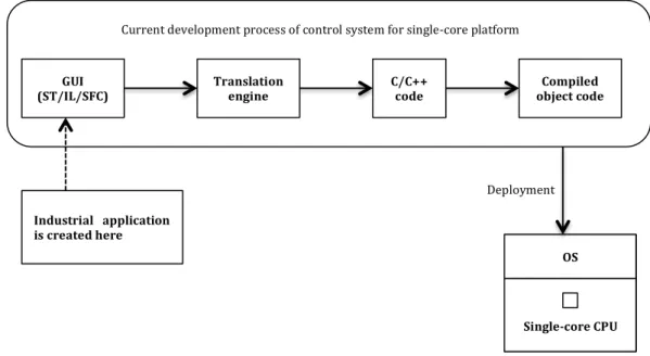
Figure 2.1 shows the working mechanism of the development process for the control system targeting at the single-‐core processor. The GUI in the development process allows PLC programmers to write programs according to the IEC 61131-‐3 standard and then the transformation engine inside the tool compiles ST/IL/SFC code into ANSI-‐C code, which can be deployed to the single-‐ core processor.
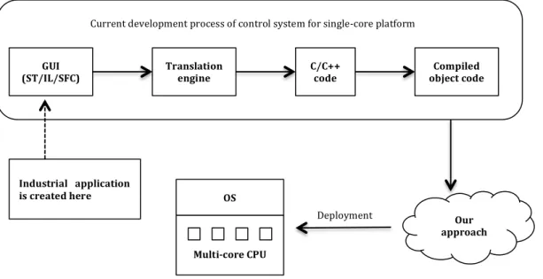
In order to make the PLC programs compatible on multi-‐core processors, our goal here is to define the function blocks (FB) in the PLC diagrams as separate tasks, which will later be assigned to different cores in the processor to run in parallel [1], as shown in Figure 2.2. To apply this method, we first need to identify the corresponding segments of generated C source code for the function blocks. Besides, the deployment policy to allocate tasks to different cores is also needed to derive an optimal partition performance [2]. As a proof of concept, the Beremiz tool is used for the demonstration of our method.
To make the tool compatible with the multi-‐core processor platform, the following subparts of the problem are as follows.
1. How does the graphical modeling part works in the current tools;
2. How are the programing languages, which are included in the IEC-‐61131-‐3 standard, especially function block diagram (FBD), converted to C/C++ code; 3. How to allocate the transformed code to the multi-‐core target platform as
well as to take care of the dependencies among different function blocks in the process of deployment to multi-‐core platform;
4. And finally, what changes should be made to the graphical modeling part so that it can be compatible with the solutions for problem 2 and 3.
Figure 2.1 The work process of current IDE tool for single-‐core platform. 1.2 Thesis Goal
The main goal of this work is to execute the industrial automation applications on a multi-‐core platform. To achieve this, three dimensions of work need to be accomplished. The first one is to build a task partition engine, which can detect all the function blocks from a C code file, which is translated from a IEC 61131-‐3 standard language based automation application. Based on the function blocks, the application is divided into several small tasks by the task partition engine. The second work is to find an effective algorithm to sort the dependencies between tasks so that the execution order won’t be disturbed when transferring to the multi-‐core platform. Last but not least, deploy the separate tasks onto a multi-‐core platform by using a certain method for parallel execution.
1.3 Thesis Outline
The rest of this thesis is organized as follows: Chapter 2 shares some background information of the industrial control system, the IEC 61131-‐3 standard as well as the multi-‐core platform. Research method and prototype used in this work are given in Chapter 3 and Chapter 4, respectively. Following
GUI
(ST/IL/SFC) Translation engine C/C++ code object code Compiled
Single-‐core CPU OS Current development process of control system for single-‐core platform
Deployment Industrial application
are several test cases and corresponding results in Chapter 5. The evaluation of the experiments is also discussed in this chapter. Some related work is given in Chapter 6 presents the related work. Finally, Chapter 7 concludes the thesis.
Figure 2.2 Our contribution in this work. GUI
(ST/IL/SFC) Translation engine C/C++ code object code Compiled
Multi-‐core CPU OS
Current development process of control system for single-‐core platform
Our approach Deployment
Industrial application is created here
2. Background and Motivation
In this chapter, the backgrounds of industrial control systems and the IEC 61131-‐3 standard are introduced. And we also introduce a free integrated development environment for developing IEC 61131-‐3 standard languages. In addition, the reason why we use a multi-‐core platform and the motivation of this work is described.
2.1Industrial Control System
There are several kinds of control systems used in the industrial domain, called by a joint name, Industrial control system (ICS). It includes supervisory control and data acquisition (SCADA) systems, distributed control systems (DCS), and programmable logic controllers (PLC), which are used widely in automation. ICSs are typically applied into such domains as food, pharmaceutical, manufacturing, chemical, energy, and mobility industries [3][4]. A control system generally consists of one or more controllers, some sensors and actuators. After data are collected from the sensors, the controllers process the data with a certain algorithm like proportional-‐integral-‐derivative (PID) and control values are calculated and delivered to the actuators such as valves and breakers. The control system must be capable to satisfy real-‐time requirements while regulating dynamic processes [2].
2.2 The IEC 61131 – 3 Standard
With the advancement of industrial control systems, more and more manufacturers develop their own products and corresponding programming languages. To meet the requirements of diverse functionality, the programming language becomes more complicated and indigestible. Therefore, it is time-‐ wasting for the programmer to learn the different languages when exchanging between different products. In addition, a programming standard is needed to enhance the substantial quality of software and system, i.e. its correctness in the sense of reliability, robustness, integrity, persistence, and safety [5].
To this end, the IEC 61131-‐3 standard [5], the first common and international standard for the software design of PLCs is proposed by the International Electrotechnical Commission (IEC), the committee for the publication of International Standards for all electrical, electronic and related technologies [6]. The standard assimilates various technologies and languages used by different vendors in the world in order to offer programmers universal languages to develop software conveniently. It is supported by a large numbers of vendors, while it is independent of any manufacturer. The advantages of the standard, including better understanding, reusability and maintainability are obvious, compared to the previous cases.
The IEC 61131-‐3 standard can be divided into two parts, Common Elements and Programming Languages. The part of Common Elements defines Data Typing,
Variables, Configuration, Resources, Tasks and Program Organization Units. There are two textual and two graphical languages in the Programming Languages part. Instruction List (IL) and Structured Text (ST) belong to the textual version while Ladder Diagram (LD) and Function Block Diagram (FBD) are part of the graphical version. In addition, a state machine definition language, named Sequential Function Chart (SFC) is also defined in the IEC 61131-‐3 standard, which graphically describes the sequential behavior of a control program [1].
2.3 Development Environment and Tools
Although the IEC 61131-‐3 standard defines a common model for designing PLC programs, it contains five different programming languages so that there still exist small incompatibilities between their implementations and possibility of switching programs between languages because of different file formats. Moreover, licenses from existing companies are so expensive that students cannot afford to program PLCs in the develop environment with IEC 61131-‐3 standard.
To this end, an open and free integrated development environment, called Beremiz [7][8], has been developed for IEC 61131-‐3 standard. It consists of a Graphic User Interface (GUI) and backend compiler. With the GUI, programs can be written in any of the five languages. Through the backend compiler, C/C++ code is generated from the programs that are written in the IEC 61131-‐3 languages and then compiled and downloaded to the single-‐core processors to be executed. In addition, Beremiz has an advantage that it is based on open standards so that it is independent of the target hardware platform.
2.4 Multi-‐core Platform
With the advancement of industries, the demands for the controllers’ computational and time-‐consuming performances are gradually increasing. Therefore, the single-‐core hardware architectures cannot satisfy the requirements of high processor performance any longer. Chip manufacturers are able to enhance the increasing processor performance through amplifying processor frequency [9], but the corresponding cost is producing overmuch quantity of heat and it does not work very well.
To this end, multi-‐core hardware architectures are designed to meet this tough requirement. A multi-‐core processor is a single Central Processing Unit (CPU) with two or more independent computing components (called "cores"), which are the units that calculate logically and execute program commands. Therefore, incorporating more cores into one single processor is helpful in boosting the performance of computing. In addition, by using multi-‐core platforms, the execution and response time of the control systems can be cut down, compared with adopting the single-‐core processor.
2.5 Discussion
systems, the Scan Cycle Time (SCT) and maintaining a High-‐Throughput Communication (HTC) [10]. As compared to single-‐core processors, SCT can be reduced and HTC can be maintained by using multi-‐core processors. Therefore, it is of great importance to apply multi-‐core platform for industrial control systems. Beremiz is competent to be used for programming languages satisfying IEC 61131-‐3 standard and allocated to single-‐core processors, but there is no attempt on the multi-‐core platform. In addition, single-‐core and multi-‐core hardware architectures are so different that new methods for the software development are need to be proposed to develop software. Then, it is difficult to find a suitable approach to make good use of the concurrency offered by multi-‐ core processors. Another obstacle is the limited understanding of the tasks allocation in control applications to different cores. Therefore, it is challenging to find a suitable scheduling policy for multi-‐core platform to partition the control applications and distribute the tasks that could be executed in parallel with the development environment, Beremiz.
3. Research Method
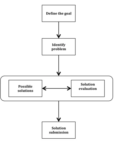
As our research belongs to the category of technique [11], so in the process of our research, we are going to adopt and follow a deductive-‐like research methodology, which can be carried out in a top-‐down approach.
First, we define the research goal by reviewing the state-‐of-‐art. In this process, the current trend of automation standard adopted in the industrial control system will be studied. In this work, our focus is on the IEC 61131-‐3. As currently the platform is transferring to multi-‐core processor, hence our research goal is to research the methods of running the applications on multi-‐ core platform.
Afterwards we identify the main challenge regarding the research goal, which is to execute the automation applications in a multi-‐core platform, the related challenge involved are to be explored. So in this stage the key problems like task scheduling algorithm, deployment policies of applications to multi-‐core platform as well as the communication mechanism between tasks and so on are explored. By identifying these challenges, we can have a deeper understanding of the problem hence getting a start point to solve it.
After the two steps have been finished, we set out to study the possible solutions for the problem. Shifting from single-‐core to multi-‐core processor includes extra consideration during the task execution, for example, how the dependencies among function blocks are affected when they are deployed onto multi-‐core platform. But once the deployment of application to the cores is fixed, we can study the possibility of using the existing single-‐core scheduling algorithm for task execution on multi-‐core. Besides, the code-‐level implementation should also be included at this stage. And as a proof of concept for our method, the Beremiz tool is used. As this tool is aimed at single-‐core platform, so the modification to the tool such as: language transformation from the programing languages included in the IEC-‐61131-‐3 standard to C/C++ code; code allocation to the multi-‐core platform as well as changes to the graphical part of the tool to make it compatible is also part of the work.
Once a promising solution is found, the best way to analyze it is to put it on test. So in this step, we work on a set of test cases to validate the proposed solution. And the test results is further to be compared with other former works in the dimensions of processor utilization, schedulability, resource argumentation and so on.
If the outcome of the proposed solution is desirable, then it can be submitted as a new solution, otherwise, solution exploring and evaluation steps will be repeated until a desirable one is found. Besides, further problems will also be discussed in this step.
The five steps are illustrated in Figure 3.1:
Figure 3.1 The process of research method. Define the goal
Identify problem Possible solutions Solution evaluation Solution submission
4. Proposed Transformation Approach
In this section, we discuss the design of the prototype that we use to validate our approach. Guided by this prototype, a general system as well as a detailed design of the whole work is given. It is also following this prototype that we apply the corresponding algorithm and methods that included in this work.
4.1 A General System Design
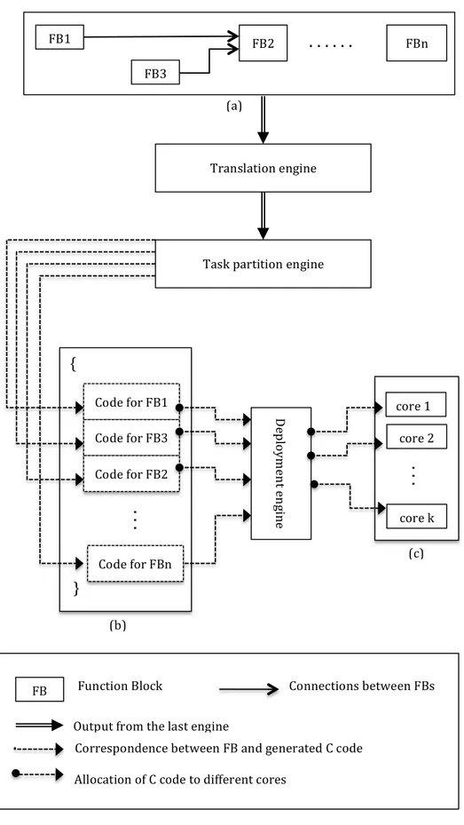
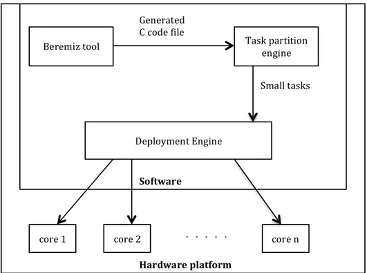
As this work is aimed for industrial automation applications, it starts with a developed process for control systems that are deployed on single-‐core platforms. In this process, the commonly used industrial applications that are written in programing languages, included in the IEC 6113-‐3 standard, are transformed to C code by a translation engine. After that, we propose two engines, task partition engine and deployment engine, to help deploy the application onto the target multi-‐core platform. This design is shown in Figure 4.1.
Modeling Language
There are five languages defined in the IEC 61131-‐3 standard, Instruction List, structured text, ladder diagram, function block diagram and sequential function chart.
Translation Engine
The translation engine is used to translate the applications, which are written in function block diagram to one whole successive C code file. So that the application can be further deployed onto a target platform to execute. Normally, nearly all the existing development tools are embedded with such engine.
Task Partition Engine
We build this engine to search through the generated C code file and identify all the function blocks as well as the corresponding variables used in the created applications. After searching, the task partition engine further divides the function blocks included in the file into small separated tasks.
Deployment Engine
The deployment engine is built to allocate the separate tasks created by the task partition engine to the target platform. As our goal aims at multi-‐core platform, so the assignment of which task goes to which core is given as an input to the deployment engine. After the deployment, the tasks can be executed on a multi-‐ core platform in parallel.
FB1 FB3 FB2 { } Code for FB1 Code for FB3 Code for FB2 core 1 core 2 (b) (a) (c)
. . .
FBn Translation engineTask partition engine
De plo ym en t e ng in e
. .
.
core kFunction Block Connections between FBs
Correspondence between FB and generated C code
Allocation of C code to different cores FB
Output from the last engine Code for FBn
. .
.
Figure 4.1 (a) FBD program in an application; (b) generated C code from the FBD program; (C) deployment of the generated C code to a dual core CPU.
Deployment Platform
The target platform is multi-‐core CPU, so that the tasks assigned to it can be executed in parallel.
4.2 A Prototype Design
We use the Beremiz tool for the development of applications using the IEC 61131-‐3 standard languages. In particular, we use the function block diagram to model the applications. The transformation engine supported by Beremiz tool tranforms the function block diagram to C code. For task partition, we first go through the generated C code file by the Beremiz tool, and return all the function blocks that are used in the application, as well as related parameters like inputs, outputs and initial values of the function blocks. Based on this information, the function blocks can further be divided into separate small tasks. Bellow is the pseudo code for this process.
Pseudo code: /*begin
1. open the C code files; 2. read the files line-‐by-‐line;
3. extract valuable information according to the key words;
4. process valuable data for tasks partition;
5. print the partitioned tasks into the files; end */
After the application is partitioned into several tasks, they are deployed onto a multi-‐core platform for parallel execution by the deployment engine. In our case a laptop with Linux environment is used. As the separate tasks are generated based on function blocks, in the process of deployment, we follow the following general guidelines [12]:
l tasks with frequent communication are allocated to one thread to
avoid extra communication overhead;
l tasks dependent closely on each other are assigned to the same core
to ensure a right execution order;
l to spare the frequent switching overhead, we usually avoids
assigning many processes to one core;
l tasks are evenly distributed after the above three rules guaranteed
to balance the load of different cores.
The detailed design of the prototype is shown in Figure 4.2.
Figure 4.2 The detailed design.
Beremiz tool Task partition
engine
Deployment Engine
core 1 core 2 core n
Generated C code file Small tasks Software Hardware platform . . . .
5. Experimental Evaluation
In this chapter, we build several test cases using the Beremiz tool to test our proposed approach and solution. The corresponding experimental results and thesis evaluation are also given.
5.1 Experimental Set-‐up
The multi-‐core platform used in our experiment is an Intel Core i5-‐430M [13] dual-‐core processor with hyper-‐threading enabled, so that four different threads can be executed in parallel on four different cores. The system runs the 64-‐bit version of the Ubuntu 12.04 LTS operating system (kernel version 3.6.11.2) without any RT patch.
5.2 Experiments
We describe the five test cases that we use in our experiments. The first test case demonstrates the problem of task communication, which is handled by setting one global variable. And in this case, only one writer and one reader can get access to it. The second test case is meant to show a scenario where there are more tasks than cores, so that more than one task needs to be allocated to one core. The third case researched task synchronization on multi-‐core platform. And the fourth one validates our solution for task dependency problem. Finally, the last test case is used compare the communication overhead between single-‐ core and multi-‐core platform.
Test Case 1: The Inter-‐task Communication
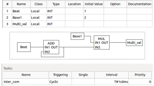
In this test case, we use the ADD and MUL function blocks. The ADD function
Figure 5.1 Function block diagram of test case 1.
block basically adds two or more inputs and provides the summation as its output. Whereas, The MUL function block multiplies the two inputs and provides the product as its output.
In Figure 5.1, the first table lists each variable, its class, data type as well as initial value (if defined) used in the corresponding function block diagram. And the variables to the left of the function block are its inputs, while the variables to the right are the outputs. For example, Beat is the input of ADD block with initial value 1, and Counter_val is the output of the MUL function block, whose initial value is not defined. The second table in Figure 5.1 gives the task we create for this function block diagram and the corresponding parameter, such as trigger type and period. In the function block diagram, the ADD function block with one of its inputs set as one and the other connected to its output, so that the output of this function block increases by one with every tick. While the MUL function block uses the output of the ADD function block as one of its inputs. The other input, Base1, is set to 2, so that its output Multi_val should be double the output of the ADD function block.
Figure 5.2 Illustration of task partition . (a) (b)
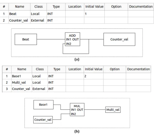
Figure 5.3 Divided tasks of test case 1: (a) ADD function block and its variables; (b) MUL function block and its variables.
task1 task2
To execute this application on a multi-‐core platform, the task partition engine divides it into two separate tasks: task Counter corresponding to the ADD function block and task Multiplier corresponding to the MUL function block, as shown in Figure 5.2. To demonstrate the inter-‐communication between the two tasks, the deployment engine introduces a shared variable, Counter_val to transmit the output of the ADD function to the input of MUL function block, as shown in Figure 5.3. The separated tasks are shown in Figure 5.3. At the deployment stage, we allocate the tasks to two different cores, and the output result is shown in Figure 5.4.
Figure 5.4 Execution results of test case 1.
From the result in Figure 5.4 it can be seen that the two tasks execute on two different cores: CPU 0 and CPU 1, which means their executions are seperate. And from the output values we can see that multi_val is double of counter_val, as expected.
Test case 2: Number of Tasks Exceeds Number of Cores
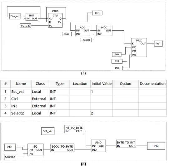
We use this test case to verify the scenario where there are more tasks than cores, which means more than one task needs to execute on the same core. In the design of this test, the partition engine split the FBD network into four different tasks. The first task corresponds to the ADD function block, the second task corresponds to the MUL function block, the third task corresponds to a selection block, which chooses between the values of the other two blocks as output, and the last one is a control task to control the selection in the third block. The corresponding function block diagrams and parameters in Beremiz are shown in Figure 5.5, to avoid repetition, we spare the whole application diagram, instead only the divided tasks are listed in the figure.
(a) (b)
(c)
(d)
Figure 5.5 Divided tasks of test case 2: (a) The ADD function block and variables; (b) The MUL function block and variables; (c) The selection function block and variables; (d) The control function block and variables.
From Figure 5.5, it can be seen that the partition engine create five global variables, IN0, IN1, IN2, Val and Ctrl, of which, IN0, IN1, IN2 are the inputs of the function block MUX, while Val and Ctrl are the output of the MUX and control signal, respectively. IN0 is the output of the ADD function block, IN1 is the output of MUL function block, and IN2 is a reset signal that always writes 1 to MUX when it is chosen. To control the selection input of MUX, we use an up count timer with a preset value of 2. While its current value is equal to the selection signal of MUX. Hence IN0, IN1 and IN2 can be selected as input. On the other hand, when one of the three inputs is selected, the other two function blocks should stop working until the selected function block stops writing. This can be done by using the Ctrl signal, which is also the current value of the CTU function block. Comparing the Ctrl value and the select1 and select2 variables, whichever is equal to Ctrl means the corresponding function block is chosen to write to the MUX function block. If neither of the two function blocks is chosen, then IN2 reset the Val to 1.
This application can be divided into four different tasks: Task_Add corresponds to the ADD function block in Figure 5.5 (a), Task_Multi corresponds to the MUL function block in Figure 5.5 (b), Task_Select corresponds to the MUX function
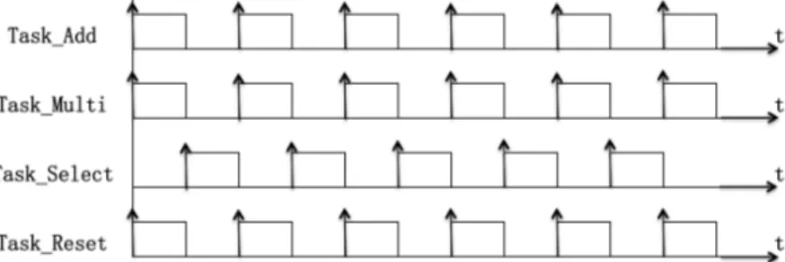
block in Figure 5.5 (c) and Task_Reset corresponds to the reset block in Figure 5.5 (d). Although the target platform that we use has four cores, at the deployment stage, we only allocate the four tasks to three cores: Task_Add and Task_Multi are deployed to core 0 and core 1, whereas Task_Select and Task_Reset are deployed to core 2. So the execution order is supposed to be as shown in Figure 5.6.
Figure 5.6 Execution order of the four tasks.
Figure 5.7 The result of test case 2.
The execution result is shown in the Figure 5.7. And from the result it can be seen that Reset_task and Select_task are executed on the same core, so their execution are in sequence instead of parallel. While Addition_task and Multiple_task are executed in parallel, as they are allocated on different cores.
Test case 3: Synchronization
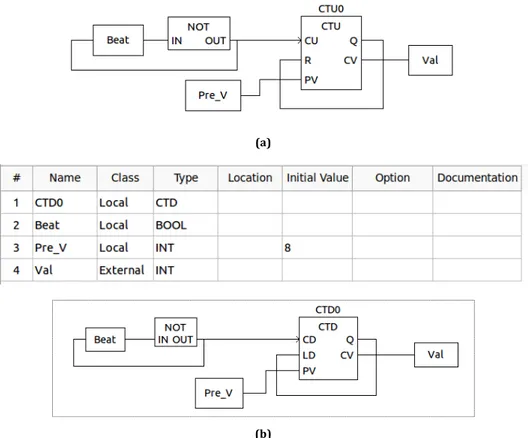
This test case is used to illustrate synchronization of tasks by deploying each of the tasks in different cores. There are two main tasks in this test. The first one is basically an up count timer, which writes its current value to a global variable. The second task is a down count timer, which also writes its current value to the same global variable. The function block diagrams of divided tasks are shown in Figure 5.8.
(a)
(b)
Figure 5.8 Divided tasks of test case 3 (a) Up count timer function block and variables; (b) Down count timer function block and variables.
To execute in parallel, the partition engine divides the application into two tasks: Up_count and Down_count, corresponding to function blocks in Figure 5.8 (a) and Figure 5.8 (b), respectively. One problem here is that both the tasks write to the same output, which will cause resource competition. To solve this problem, we use semaphore to guard the shared variable Val. So every time either of the tasks wants to write to Val, it needs to acquire the semaphore and only when the semaphore has been acquired the task can write to Val, otherwise, it has to wait until it gets the semaphore. The working mechanism is shown in Figure 5.9.
Figure 5.9 A solution with semaphore for test case 3.
Figure 5.10 Execution result of test case 3 on target platform.
From the result above, we can conclude that each task can write its current value to the shared variable without race condition.
Test case 4: Tasks Dependency
As discussed above, one of the main problems in transferring from single-‐core platform to multi-‐core platform is the task dependency. That is, on a single-‐core platform, only one task can execute at one time, so it is relatively easy to keep the execution order of the tasks. On a multi-‐core platform, however, more than one task can execute in parallel at the same time, which may interfere the desired execution order of the tasks in the application. In this test case, we demonstrate a scenario where the execution of one task depends on the outputs of several other tasks. The function block diagram is shown in Figure 5.11.
Figure 5.11 Function block diagram of test case 4
From the function block diagram in Figure 5.11, it can be seen that the inputs of the second ADD function block are the outputs of the first ADD function block and the MUL function block, which means the second ADD function block can only execute after the other two function blocks have finished their execution.
Figure 5.12 Function block diagram of test case 4 with global variables
To follow this dependency, we change Mul_val from local variable to a global one, and add another global variable, Add_val, between the first and second ADD function block, thus the second ADD block can read freely from the shared resources. The change is shown in Figure 5.12 marked by red block. With such changes, the application can be divided into 3 separate tasks, shown in Figure 5.13. (a) (b)
(c)
Figure 5.13 Divided tasks for test case 4, (a) The first ADD function block and variables; (b) MUL function block and variables; (c) The second ADD function block and variables.
The results of the experiment are given in Figure 5.14. From the result it can be seen that the Final_val is the sum of Add_val and Mul_val, which means the execution of the three tasks do follow the expected execution order.
Figure 5.14 Experiment results of test case 4.
Test case 5: Communication Overhead on Multi-‐core
The most attractive advantage of multi-‐core platform is to make the true parallelism possible. To some extent, such parallel execution can significantly decrease the execution time of the application, hence increasing the working rate of the platform further more. However, distributing on different cores, tasks communication can take longer time than that of locating on the same core, which can be shown in Figure 5.15.
In this test case, we propose an application to compare the communication overhead between execution of an application on single-‐core and multi-‐core platform. The divided tasks are shown in Figure 5.16.
Figure 5.15 Tasks communication between different cores (a) (b) Write data to a variable
Read data from a variable Network
A Network B Network C Network D Global variable
2 Global variable
1
(c) (d)
Figure 5.16 Divided tasks for test case 5 (a) The first CTU task and variables; (b) The second CTU task and variables; (c) The CTD task and variables; (d) The MUL task and variables.
The application has been divided into four separate tasks as shown in Figure 5.16 (a), (b), (c) and (d), and the task (a) and task (b) has been allocated to CPU 0, while task (c) and task (d) to CPU 1. As designed in the application, task (b) and (c) need the signal from the task (a) to invoke, and task (d) requires the outputs from task (b) and task (c). As tasks run on multi-‐core can execute in parallel, which can decrease the running time, to eliminate such effect, we set a semaphore to regulate the execution of tasks. That is whenever a task is ready to execute, it has to ask for the semaphore, and only when the semaphore is successfully acquired, it can start its execution. Even though the tasks are on different cores, the execution order of tasks is still sequential. To compare, we also deploy the tasks on the same core and get the execution time. We run the application 1000 times on both single-‐core and multi-‐core, and according to the results, the average execution time on single-‐core is 24.141us, while the average execution time on multi-‐core is 88.949us.
From the results we can conclude that it takes more time to run the application on a multi-‐core than to run it on a single-‐core platform. An explanation for this is that, for a multi-‐core platform, different cores use different caches, where global variable is passed from one core to another, the cores need to write and read from a common cache, which takes more time than reading its own cache. And in the application we build for this test case, one input of task (c) comes from the output of task (a), sig. The two tasks are allocated on different cores, so the variable sig is treated as a global variable, which takes more time to write and read. Likewise, variable IN1 is also a global variable because task (b) and task (d) are on different cores. As stated above, the parallel execution on the multi-‐core is constrained by the use of a semaphore, so there is no difference in execution on multi-‐core and single-‐core except the global variables. Hence, the
increase in the execution time on multi-‐core adds an extra communication overhead as compared to the execution on a single-‐core platform.
5.3 Discussion
Based on the five test cases above, we have resolved problems of inter-‐task communication, task synchronization and dependency when transferring from single-‐core platform to multi-‐core platform by building our own task partition engine and deployment engine. For the inter-‐task communication, we use a global variable, which can be written and read by all the relevant tasks. However, when more than one task requires access to a share resource, it may bring up the problem of task synchronization. In such situation, the output of one task may be overwritten by other tasks. Similarly, a task may overwrite the outputs of other tasks that share a same resource with it. To solve this problem, we have used the semaphore to control the access to the shared resource. Thus, when one task wants to get access to the shared resource, it needs to acquire the semaphore first. Only when the task has successfully taken the semaphore, it can gain access to the required resource. Besides, divided into several small tasks, an industrial automation application can execute in parallel on a multi-‐ core platform, which can also interfere its original execution order, as some tasks are dependent on other tasks inputs. To resolve this task dependency problem, we introduce global variables so that the following tasks which is dependent on former task can read freely from the share resources. To further test our work, we have also designed some cases where the number of divided tasks is more than the number of cores, so that more than one task has to be allocated to each core. From the results of the test cases, we can conclude that, the partition engine and deployment engine as well as the algorithm we adopted for the relevant problems are effective and promising for further utilization.
Nevertheless, the parallelism of multi-‐core platform can also cause problems like communication overhead increase while it increases the working rate of the platform, which is demonstrated by test case 5, as to read and write the global variables from a shared cache of different cores takes more time than from the cache owned by one core. In conclusion, multi-‐core platform is a very effective solution for current industrial automation bottleneck, but some side effects should also be fully considered and taken good care of.
