Control of HCCI by aid of Variable Valve
Timings with Specialization in Usage of a
Non-Linear Quasi-Static Compensation
TRITA-MMK 2006:06 ISSN 1400-1179
ISRN KTH/MMK/R--06/06--SE
KTH School of Industrial Engineering and Management Department of Machine Design Royal Institute of Technology SE-100 44 Stockholm, Sweden
Academic thesis, which with the approval of Kungliga Tekniska Högskolan, will be presented for public review in fulfillment of the requirements for a Doctorate of Engineering in Machine design. The public review is held at Kungliga Tekniska Högskolan, F3, Lindstedsvägen 26, Stockholm; at 14:00 on the 4:th of
September 2006. © Fredrik Agrell, 2006
ABSTRACT
This doctoral thesis is about controlling the combustion timing of the combustion concept Homogeneous Charge Compression Ignition, HCCI, by means of variable valve timings.
The HCCI research usually is regarded to have started in Japan during the later part of the 1970´s. The world of HCCI has since grown and HCCI is of today researched worldwide. Of particular interest from a Swedish point of view is that Lund Institute of Technology has emerged as one of the world leading HCCI laboratories.
The idea with HCCI is to combine the Otto and Diesel engine. As in an Otto engine the charge is premixed but as in a Diesel engine the operation is unthrottled and the compression heat causes the ignition. The combustion that follows the ignition takes place homogeneously and overall lean. The result is ultra low NOx and particulate emissions combined with high total efficiency. A difficulty with the HCCI-concept is that it only works in a narrow area and that there is no direct way to control the Start Of Combustion, SOC. Out of this follows that timing/phasing of the combustion is one of the main difficulties with HCCI combustion concepts. This is particularly emphasized during transient operation and calls for feedback control of the combustion timing.
This work investigates one method, the variable valve timing, to achieve feedback control of the combustion phasing. From the work it can be concluded that the variable valve timing can control the combustion phasing during engine transients. In order to improve the performance a non-linear compensation from ignition delay to valve timings has been suggested, incorporated in a control structure and tested in engine test. The engine test has been performed in a single cylinder engine based on a Scania truck engine. The speed range from 500 to 1750 rpm and the
ACKNOWLEDGMENTS
This work is part of an industrial research program between Scania CV AB and The Royal Institute of Technology, KTH. Financial support from the Swedish Government is also kindly acknowledged.
Thanks to Hans-Erik Ångstrom, Division of Internal Combustion Engines at KTH, for providing the opportunity to do this work and also for invaluable help in doing it.
Thanks to Eric Lycke, Internal Combustion Engines Laboratory at KTH, for invaluable help.
Thanks to Johan Linderyd, Scania CV AB, for outstanding project management and interesting HCCI discussions.
Thanks to Bengt Eriksson and Jan Wikander, Division of Mechatronics at KTH, for interesting control discussions.
Thanks to Colette Castell Hernández, Lena Larsson, Mikael Lundström, Daniel Ståhl and Freddie Tydal for valuable thesis works.
Thanks to all friends/colleagues, past and present, at Scania CV AB and KTH.
Finally, a special thanks to all beautiful high performance naturally aspirated engines of the world for challenge the need to know, display a refinement beyond belief, prove that there always are more to learn and bring a sense of humble admiration that makes every distance covered in their company even more joyful.
LIST OF PAPERS
This thesis includes the following publications. The papers are appended at the end. A summary of each paper and statement about the contribution by the author to each of them are found in the “The Work”-section.
Paper I. SAE 2003-01-0748.
Integrated Simulation and Engine Test of Closed Loop HCCI Control by aid of Variable Valve Timings. Fredrik Agrell, Hans-Erik Ångström, Bengt Eriksson, Jan Wikander and Johan Linderyd. Paper II. SAE 2003-01-3172.
Transient Control of HCCI Through Combined Intake and Exhaust Valve Actuation. Fredrik Agrell, Hans-Erik Ångström, Bengt Eriksson, Jan Wikander and Johan Linderyd.
Paper III. SAE 2005-01-0131.
Control of HCCI During Engine Transients by aid of Variable Valve Timings Through the use of Model Based Non-Linear
Compensation. Fredrik Agrell, Hans-Erik Ångström, Bengt Eriksson, Jan Wikander and Johan Linderyd.
Paper IV. SAE 2005-01-2128.
Transient Control of HCCI Combustion by aid of Variable Valve Timing Through the use of a Engine State Corrected
CA50-Controller Combined with an In-Cylinder State Estimator Estimating Lambda. Fredrik Agrell, Hans-Erik Ångström, Bengt Eriksson, Jan Wikander and Johan Linderyd.
Paper V. KTH Internal Combustion Engine Report MFM 162. Practical Modeling of HCCI for Combustion Timing Control and
CONTENT
INTRODUCTION ...1
IC-ENGINES NOMENCLATURE AND EMISSIONS ...4
WORKING PRINCIPLE...4 VALVE TIMINGS...8 VOLUMETRIC EFFICIENCY ...12 LAMBDA...12 LAMBDA SENSOR ...13 CHARGING SYSTEM ...13 REACTIONS...14 COMBUSTION CHARACTERISTIC ...14 MEAN PRESSURES...18
EMISSIONS AND THEIR ENVIRONMENTAL IMPACT ...19
EGR...20
AFTERTREATMENT...21
HCCI IN GENERAL...23
COMBUSTION AND MIXTURE FORMATION ...23
Otto engine...23
Diesel engine ...27
HCCI engine...29
Pros and cons of HCCI combustion...31
HISTORY...31
CONCEPTS...33
COMBUSTION SIMULATION ...36
CONTROL ...37
Rough SOC model...39
Control of two-stroke...40
Control of four-stroke ...42
Control through valve timings in detail...44
Feedback signal ...47
Dynamic properties ...48
Transient ...48
Mode switch ...49
ENGINE CONTROL ...51
CONTROL OF THE OTTO ENGINE...52
Lambda control ...52
Ignition timing control ...55
THE WORK ...58
AIM ...58
EQUIPMENT ...59
Simulation ...61
APPENDED PAPERS ...62
Paper history ...62
Summary of Paper I ...63
Summary of Paper II ...64
Summary of Paper III ...65
Summary of Paper IV...66
Summary of Paper V...67
POSITIONING OF THE WORK ...68
FUTURE WORK...68 PROJECT CONCLUSION...71 RELATED PUBLICATIONS ...71 SAE Transactions ...71 Patents ...71 Thesis works ...72 REFERENCES ...73
INTRODUCTION
During recent years an increased environmental awareness has lead to stricter emission rules for vehicles and thereby vehicular engines.
Table 1. Emission levels for Heavy Duty truck engines as stated in [1].
Legislation From Year NOx
[g/kWh] Particulates [g/kWh] Euro I 1992 8.0 0.36 Euro II 1996 7.0 0.25 Euro III 2000 5.0 0.10 Euro IV 2005 3.5 0.02 Euro V 2008 2.0 0.02 EPA 07-10, US 2007-2010 0.27 0.013
In combination with higher fuel prices and the growing concern for the large scale burning of fossil fuels causing a global warming, the vehicular drive train development is directed in mainly two different directions. One direction aims away from the fossil fuel and into the hydrogen society by means of the fuel cell. The fuels cell converts chemically bounded energy by means of a “cold” combustion to electricity. The process has a high efficiency and the only bi products are water and heat. The direction faces technical challenges in a number of areas. The first area is the fuel area. Shall one choose to in a first stage go for the direct hydrogen route or use onboard reformation of hydrogen from a hydrocarbon fuel? If one goes for the direct hydrogen route how shall the
hydrogen be produced and distributed? If one chooses the reformation route what fuel is to be used and what total efficiency will result? Another area of uncertainty is the cost as a fuel cell contains large amount of precious metal and if one chooses the direct hydrogen route, it calls for large infrastructure investments. What will the series production cost be and how much will the infrastructure investments be? The cost issue also raises concern about the market penetration especially for developing markets. One can also question the technologies applicability and cost in applications such as long haulage trucks in the foreseeable future.
The above challenges motivate refinement of the Internal Combustion Engine, IC-Engine, which is the other route of drive train development. The world of IC-Engines is coarsely divided in two variants, the Otto engine and the Diesel engine. The Otto-engine, or the petrol engine, benefits in very low emissions but suffers of bad efficiency. The Diesel engine benefits in good efficiency but suffers with high emissions in the form of Nitrogen Oxides, NOx, and particulate.
The way to improve the Otto-engines efficiency is to lower the gas exchange loss. Lean burn combustion concepts, flexible valve trains, downsized engines or combinations thereof can achieve this. The principal drawback with the lean burn route is that in order to keep the NOx emission within legal limits new after treatment technology has to be deployed. The after treatment technology is expensive and the use of low sulphur gasoline desirable. The flexible valve train route calls for complicated mechanical/electromechanically/hydraulic systems that this far has not found wide spread use. The drawback with the downsized engines is a reduction in maximum engine power. The efficiency of a Diesel seems in neither case possible to achieve.
aftertreatment technology is the probable road. As for the lean burn gasoline case the Diesel after treatment systems generally prefer low sulphur fuel.
However, in order to fulfill EPA 07-10, as is proposed for the US market beyond 2007, with the IC-Engine and keep the fuel consumption down, after treatment may not be enough. In order to meet such legislations utilization of some form of Homogeneous Charge Compression Ignition, HCCI, combustion concept, at least in parts of the engine operation area, seems to be a promising solution. The idea with HCCI is to combine the Otto and Diesel engine. As in an Otto engine, the charge is premixed but as in a Diesel engine the operation is unthrottled and the compression heat causes the ignition. The lean premixed charge burns overall lean which results in ultra low NOx and particulate emissions combined with high total efficiency. A difficulty with the HCCI-concept is that it only work in a narrow area and that there is no direct way to control the Start Of Combustion, SOC. Out of this follows that timing/phasing of the combustion is one of the main difficulties with HCCI combustion concepts. This is particularly emphasized during transient operation and calls for feedback control of the combustion timing.
This work investigates one method, the variable valve timing, to achieve feedback control of the combustion phasing in HCCI combustion.
IC-ENGINES NOMENCLATURE AND EMISSIONS
The following sections are based on [2] and [3] if nothing else are stated. WORKING PRINCIPLE
The general aim of an IC-Engine is to convert chemically bounded energy to mechanical work. The most common principle to achieve this is by means of a piston and crank mechanism as shown in Figure 1. The piston moves back and forth along a straight line. The straight motion of the piston is through the crank arrangement converted to a rotation of the crankshaft. The top position for the piston is called Top Dead Center, TDC, and the bottom position is called Bottom Dead Center, BDC.
c t d
V
V
V
=
−
(1)
c tV
V
=
ε
(2)
Vc - Cylinder volume remaining with the piston at TDC, Compression Volume
Vt - Cylinder volume that is present with the piston at BDC, Total Volume
Vd – Displaced Volume as the piston moves between BDC and TDC, Swept Volume
It is possible to deduce theoretical expressions for the total efficiency that show that in order to raise the efficiency the CR shall be chosen as high as possible.
The IC-Engine world is largely dived in two-stroke and four-stroke engines, with respect to the working principal, and further divided, with respect to the combustion system. The four-stroke principle is shown in Figure 2 and can be explained as follows.
Figure 2. Schematic of the four-stroke process. Picture from [2].
1. The intake stroke start with the piston at TDC and ends when the piston has reached BDC. As the piston travels from TDC to BDC the inlet valve is open thereby allowing a fresh combustible charge to be sucked into the cylinder. The inlet valve has opened shortly before the start of the stroke and closes shortly after that the stroke ends in order to maximize the charge mass.
2. The compression stroke starts right after the intake stroke with the piston at BDC. All valves are closed and as the piston moves from BDC to TDC, the mixture that was inhaled during the intake stroke is compressed. Shortly before the end of the stroke the combustion of the charge starts.
3. The expansion stroke follows the compression stroke. The stroke starts with the piston at TDC and ends with the piston at BDC. During the first part of the stroke the combustion continues and raises the pressure of the charge. The elevated pressure pushes the piston down towards BDC and transfers useful work to the crankshaft. Close to BDC the exhaust valve is opened. 4. The exhaust stroke follows the expansion stroke. During the
stroke the burnt charge is pushed out of the cylinder through the exhaust valve, which remains open until shortly after TDC. The start of the gas exchange is helped by a remaining high pressure from the combustion and completed by means of the piston motion from BDC to TDC. At the end of the stroke the inlet valve opens and the process starts all over again.
The four-stroke principle needs two revolutions of the crankshaft in order to complete the cycle and can only be realized with a complicated valve mechanism. In order to increase the power output and simplify the design, the two-stroke principle emerged. The two-stroke principle, that utilizes one revolution pro cycle, is shown in Figure 3 and can be explained as follows.
Figure 3. Schematic of the two-stroke process. Picture from [2].
1. The compression stroke starts with the piston in BDC and continues until the piston has reached TDC. The piston covers during the motion first the transfer port and later the exhaust port. As the piston moves towards TDC, the cylinder charge is compressed while fresh charge is sucked into the crankcase. The later is also a consequence of the piston motion that drives the gas motion. When the piston approaches TDC the combustion is started.
2. The expansion stroke starts right after the compression stroke. During the first part of the stroke the combustion continues and raises the pressure of the charge. The elevated pressure pushes
the piston down towards BDC and transfers useful work to the crankshaft. Close to BDC the exhaust port is uncovered and a portion of the burnt charge is pushed out of the cylinder through the exhaust port helped by a remaining high pressure from the combustion. As the piston continues towards BDC the transfer port is uncovered allowing the fresh charge to enter the cylinder and complete the gas exchange by pushing out the remaining burnt charge. This is helped by the fact that the fresh charge is compressed in the crankcase by the piston motion from TDC to BDC. To let new air to enter into the crankcase a reed valve can be used as shown in Figure 3. When the piston has reached BDC and starts to move toward TDC the cycle is completed and starts all over again.
The two-stroke concept can at a first glance seem to be superior to the four-stroke concept. That is although not the case as the uncontrolled gas exchange process makes it hard to completely get rid of all burnt charge in the cylinder and to avoid fresh charge to directly enter the exhaust. The result is that the four-stroke principle in general has lower fuel consumption and fewer emissions. Therefore the following will be concentrated on the four-stroke principle as it due to superior fuel consumption and superior emission characteristics is the dominant concept in vehicular applications.
VALVE TIMINGS
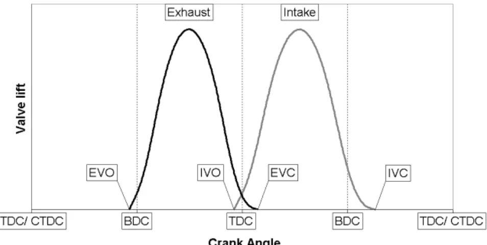
Typical valve lifts for a four-stroke engine are shown in Figure 4. In a four-stroke engine one complete working cycle equals two revolutions of the crankshaft corresponding to a rotation through 720 Crank Angle Degree, CAD. TDC at the end of the compression stroke will in the following be defined as 0 CAD and in the following occasionally be called Compression Top Dead Center, CTDC. The most common arrangement
Figure 4. Principle valve lifts as a function of crank angle.
The characteristic of the valve timing is usually defined by the opening and closure events with the notation as follows.
EVO - Exhaust Valve Opening EVC - Exhaust Valve Closure IVO - Inlet Valve Opening IVC - Inlet Valve Closure
Another important valve timing characteristic is called Overlap and is the period in the gas exchange event during which both inlet and exhaust valves are open at the same time. The size of the Overlap is defined as the crank angle difference according to Equation 3.
IVO
EVC
The valve lifts are usually accomplished by a cam mechanism. In Figure 5, four common arrangements are shown.
Figure 5. Different types of valve trains. Picture from [3].
The lift occurs when the camshaft rotates and as a consequence forces the valves to move. The camshaft is connected to the crankshaft over a gear that causes the camshaft to rotate with half the speed of the crankshaft. In order to optimize the gas exchange process, the tendency is that these mechanisms allow more and more valve lift flexibility. The use of a camphaser, that allows phasing of the camshaft with respect to the crankshaft thereby allowing a phasing of the valve lift, is wide spread. The development trend is towards fully flexible valve train that allows the valve lifts to be optimized for each engine operating condition. A wide variety of more or less variable systems have during the time of history emerged and the development has in recent years accelerated. As an example one can mention Porsches VarioCam Plus described in [4]. Out of the systems that principally allow fully variable valve timings FEV’s electromechanical system [5] and Louts electro hydraulic system [6] can be mentioned. The most advanced valve train today in production is the BMW Valvetronic system shown in Figure 6, and described in [7] and [8]. The mechanism is applied on the intake valves and allows the intake
Figure 6. BMW Valvetronic mechanism. Picture from [7].
As a consequence of the mechanism the duration of the valve lift is varied as a function of the lift thereby avoiding excessive valve acceleration. The lift mechanism is combined with a camphaser making it possible to, in principle, choose IVO and IVC free of each other.
VOLUMETRIC EFFICIENCY
A quality measure of the gas exchange process is called the volumetric efficiency. Volumetric efficiency is defined as the ratio between the actual inhaled air volume divided by the ideal displaced air volume according to Equation 4. d air in , air vol
V
m
ρ
η
=
(4)
mair,in - Mass of air inducted into the cylinder at each cycle ρair - Density of the air
Vd - Swept volume
As seen in Equation 4 the actual air volume is mass based and recalculated to volume by division with a reference density. The reference density can either be taken as the inlet air density or as the surrounding air density. In the later case the volumetric efficiency is not only a quality measure of the valve timing event and port design but of the whole air supply system of the engine.
LAMBDA
Lambda, λ, is defined as the ratio between the air mass that is present during the combustion and the mass of air that theoretically is consumed in order to combust the present fuel completely.
fuel air
m
*
Z
m
=
λ
(5)
mfuel - Mass of fuel in the cylinder at each cycle
Z can be calculated as the relationship between the molecular weight between air and fuel that is required for stoichiometric combustion. The definition of stoichiometric combustion is a combustion that precisely consumes the present fuel and the present oxygen. For gasoline Z is approximately 14.5.
LAMBDA SENSOR
In modern production Otto-engines a lambda sensor predominately is used. It is placed in the exhaust systems as close to the engine as possible with respect to thermal stress. The historical most well known sensor is the zirconium dioxide sensor. It basically consists of an electrolyte, zirconium dioxide, which on one side is in contract with the exhaust gases and on the other side is in contact with the ambient air. The sensor outputs a voltage as consequence of the difference in partial oxygen pressure between the two sides of the electrolyte. If the engine is operated at a lambda below one the output voltage is in the 0.8- 1.0 V range while it for lambda above one is about 0.1 V. The transition between the two voltage levels takes place in a step like manner at λ=1. CHARGING SYSTEM
All combustion systems display a lowest possible λ-value. As the amount of energy conversion that takes place in an engine is dependant on the fuel amount present in the cylinder, the maximum power output of the engine, for each engine speed, is related to the maximum amount of air that can be present in the cylinder. For this reason, the air supply system, the charging system, is crucial for the engine performance and also used for classification.
One class of engines is the naturally aspirated engines. The engine type relies on tuning of pressure wave interaction in the pipes of the charging system to maximize the air amount in the cylinder. The second engine class is the supercharged, or boosted, engines. In these engines a
compressor raises the pressure before the inlet valve resulting in an increased air amount in the cylinder. The compressor can be driven from the crank shaft of the engine, mechanical supercharging, or driven by a turbine that in turn is driven by the exhaust stream of the engine, turbo charging.
REACTIONS
The reaction formula for the oxidation, combustion, of a general hydrocarbon fuel in dry air at λ≥1 can be written as
(
)
2 2 2 2 2 2 yN
*
773
.
3
*
4
y
1
O
4
y
1
1
0
H
2
y
CO
)
N
*
773
.
3
O
(
4
y
1
CH
+
+
+
−
+
+
⇒
+
+
+
λ
λ
λ
(6)
if dry air is regarded to be composed of
2
2
3
.
773
*
N
O
+
(7)
COMBUSTION CHARACTERISTIC
The rate at which the chemically bounded energy of the fuel is converted to heat during the combustion can be deduced from the measured cylinder pressure. Under the assumption that heat is released in the whole combustion chamber at homogeneous conditions, that the gases can be regarded as ideal gases and that there are no mass losses occurring, the following expression can be deduced for the crank angle derivative of the released heat, dQ/dθ.
θ
θ
κ
κ
θ
κ
θ
d
dQ
d
dV
p
1
d
dp
V
1
1
d
dQ
ht+
−
+
−
=
(8)
v pc
c
=
κ
(9)
θ - Crank Anglecp - Specific heat at constant pressure cv - Specific heat at constant volume p - Cylinder pressure
V - Cylinder volume
Qht - Heat transfer to the walls
The time derivative of the heat transfer to the walls, Q&ht, can be calculated as follows.
)
T
T
(
A
*
ha
Q
i i A g i ht=
∑
−
&
(10)
ha - Heat transfer coefficientAi - Area of wall element i Tg - Temperature of the gas TAi - Temperature of wall element i
The heat transfer coefficient for the compression and expansion stroke, ha, can be calculated according to the Woschni relationship described in [9] as follows.
(
mot)
0.8 ref ref ref d 3 pis 2 53 . 0 g 2 . 0 8 . 0 1p
p
V
p
T
V
K
C
K
T
b
p
K
ha
−
+
=
(11)
p - Cylinder pressure b - Piston diameterTg - Temperature of the gas
Cpis - Mean piston speed during the stroke Vd - Swept volume
Tref, Pref, Vref - Temperature, Pressure, Cylinder volume at a reference state
pmot - Cylinder pressure if the engine had been motored K1=0.13
K2= 2.28+0.308*Cper/Cpis
Cper - Peripheral velocity of the gas K3=0 for the compression stroke K3=3.24*10-3 for the expansion stroke
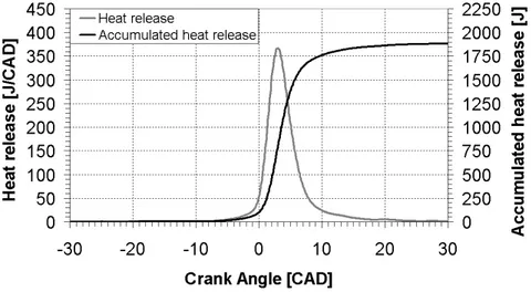
The coefficient K1, K2 and K3 are usually in need of tuning in order to achieve god results. A reasonable well-tuned example is shown in Figure 7. Also shown in Figure 7 is the integrated heat release named accumulated heat release.
Figure 7. Principle heat release and accumulated heat release.
From the accumulated heat release, a number of combustion specific parameters are deduced. Two of them are Start Of Combustion, SOC and Crank Angle for 50 percent burnt, CA50.
SOC is formally the crank angle at which the accumulated heat release raises from zero. Due to uncertainties in the heat release calculation SOC is here defined as the crank angle when two percent of the total released heat has been released.
CA50 is defined as the crank angle when 50 percent of the total released heat has been released.
MEAN PRESSURES
A number of pressures are commonly used in order to compare the load level between engines of different sizes and different concepts.
Gross Indicted Mean Effective Pressure, grossIMEP, is defined according to Equation 12.
∫
=
pdV
V
1
grossIMEP
d(12)
p - Cylinder pressure V - Cylinder volume Vd - Swept volumeThe integral is in the case of grossIMEP evaluated during the compression and expansion stroke.
Net Indicted Mean Effective Pressure, netIMEP, is also defined by Equation 12 with the difference that the integral is evaluated during the whole four stroke process. The difference between grossIMEP and netIMEP is caused by the gas exchange process and is called Pumping Mean Effective Pressure, PMEP.
Brake Mean Effective Pressure, BMEP, is for a four-stroke engine defined according to Equation 13.
d
V
M
4
BMEP
=
π
(13)
M - Torque delivered at the crankshaft Vd - Swept volumeThe difference between netIMEP and BMEP is caused by the engine friction and is named Friction Mean Effective Pressure, FMEP.
EMISSIONS AND THEIR ENVIRONMENTAL IMPACT
As seen from Equation 6, an ideal combustion of a hydrocarbon fuel result in Carbon Dioxide, CO2, and water, H2O. CO2 is generally regarded to be one of the main contributors to global warming. As can be concluded from Equation 6, the CO2 emission is directly linked to the amount of burned fuel and can therefore only be reduced by lowering the burnt fuel amount. An alternative is to burn a fuel that originates from a renewable source and thereby do not add CO2 to the atmosphere.
The emissions that are controlled by emission legislations are hydrocarbon, HC, Carbon Monoxide, CO, NOx and Particulate Matter, PM. Below the origin of these emissions will be explained and there environmental impact discussed.
HC and CO appears principally as a result of incomplete combustion. HC can be regarded as unburned or partially burned fuel and is therefore present in a wide variety of species. Some of these spices are toxic and carcinogenic. According to [10], HC also reacts with NOx under the influence of sunshine forming oxidants, ground level ozone, which damages plants life, irritates the mucous membrane and participates in the formation of SMOG. CO is directly toxic and causes death if inhaled in enough quantities, which in practice only can occur in confided spaces.
NOx is mainly formed as a result of oxidation of the N2, that is present in the air according to Equation 7, into NO. Oxidation of N2 occurs at high temperatures and is described by the Zeldovich mechanism. NO is subsequently oxidized into NO2 and the two species are usually treated with the notation NOx. NOx reacts with HC under the influence of sunshine to form oxidants as is stated above. NOx is also according to [10] a major contributor to acid precipitation.
Particulates or Particulate Matter, PM, is regarded as all substances, except unbound water, which under normal circumstances are present in exhaust gases in solid or liquid state. It is mainly present in the exhaust as soot that originates from fuel rich combustion. Other particulate sources that becomes important when the allowable particulate emission is lowered is engine wear and lube oil residues. PM is considered to irritate the mucous membrane, give airway disorder, reduce lung function and contribute to SMOG.
Sulphur dioxide, SO2, is another important air pollutant. It existence in the exhaust is although a consequence of the sulphur content of the fuel and therefore not regulated in vehicular emission standards. SO2 causes according to [10] acid precipitation and also, according to [11], SMOG. EGR
Exhaust Gas Recirculation, EGR, is a commonly deployed technique to reduce NOx emission. The idea is to feed the intake of the engine with a certain amount of the engines own exhaust. NOx is hereby reduced due to that the oxygen concentration in the intake charge is lowered and also due to the fact that the exhaust gas contains a reasonable amount of CO2, which have a high specific heat thereby reducing peek temperatures. Residuals left within the cylinder from the previous combustion is sometimes referred to as internal EGR. The name is
AFTERTREATMENT
Aftertreatment of the exhaust gases from an IC-Engine is usually accomplished with catalytic techniques. In the following, a few basic techniques are presented. The following section are based on [12] and [13].
Oxidation catalysts are used in order to oxidize HC and CO and to some extent reduce PM levels. This type of catalysts requires that there is oxygen present in the exhaust thereby implying a lean combustion or the introduction of air in the exhaust pipe in front of the catalyst.
Figure 8. Principle three-way catalyst. Picture from [14].
Another type, shown in Figure 8, is the three-way catalyst, or the selective catalyst, which manages to oxidize HC and CO while at the same time reduce NOx. The converter works if λ are kept close to one. If λ are larger than one NOx will not be significantly reduced and the catalyst removes only HC and CO. At λ below one, on the other hand, NOx will be reduced but HC and CO will not be significantly oxidized. In order to reduce NOx in a lean environment a number of different techniques have been presented during recent time. One principle is the NOx-storage catalyst that stores NOx in the catalyst. NOx that is stored
in the catalyst is reduced intermittently during so-called regeneration modes. During regeneration λ is lowered to below one thereby making NOx reduction possible.
Selective Catalytic Reduction, SCR, is another technique to reduce NOx in a lean environment. In this case a urea solution is mixed into the exhaust stream. Urea forms ammonia, in the warm exhaust gas stream, that in turn selectively reacts with NOx on a catalyst thereby forming nitrogen.
During recent years particulate traps have been introduced as a mean to lower the PM emission from Diesel engines. The PM is stored in the trap and when the trap is full the particulate is burnt during a regeneration mode. Peugeot has introduced a trap system in which the regeneration is helped by post-injection of diesel and the introduction of Eolys to the fuel [15]. Eolys, a trade name, helps the regeneration by lowering of the regeneration temperature. Another type is the Continuously Regenerating Trap, CRT, were the NO emissions are used to in a continuous manner oxidize the particulate.
The active part in a three-way, NOx storage and many oxidation catalysts is precious metal that are sensitive to lead. Many other catalyst systems also show sensitivity against lead. Therefore it is essential that no lead is present in the fuel. Another compound that causes problem for the after treatment systems is sulphur. Sulphur poisons the active materials in the catalysts making them inactive. The problem can although be dealt with, at least partially. If the exhaust temperature is high enough, or can be raised during certain operation modes together with low λ, the sulphur poisoning the active layers can be close to completely removed at appropriate conditions. Sulphur is also known to break desirable reaction chains in particulate traps of CRT type thereby making the trap inactive. It is therefore desirable, and in some
HCCI IN GENERAL
HCCI has the attractive feature of low particulate emission and low NOx emission combined with high efficiency. In order to explain the origin of the benefits with HCCI combustion, a comparison with the Otto and Diesel concepts is required.
COMBUSTION AND MIXTURE FORMATION
The following sections about the Otto and Diesel processes are based on [2] and [3].
Otto engine
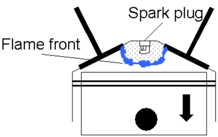
Figure 9. Schematic Otto-Combustion.
In the classical Otto engine a homogeneous air fuel mixture is inhaled in the cylinder and ignited by a spark from a spark plug. The Otto engine is also known as the petrol engine or Spark Ignited Engine, SI-Engine. As a result of the spark, a flame starts to propagate in the charge spherically from the spark plug subsequently consuming the charge as described by
Figure 9. The small scale turbulent mixing of the charge influences the speed at which the flame propagates in the combustion chamber. The compression ratio used is limited in order to avoid self-ignition of the charge in front of the flame front. The self-ignition phenomenon is called knocking combustion due to the often clearly audible combustion noise that is a consequence of pressure waves propagating the combustion chamber. The knock phenomenon is known to cause severe engine damages and must therefore be avoided.
The spark ignition is only possible in a quite narrow λ-range. The result is that the flame burns at close to stoichiometric conditions, which results in a high flame temperature and in turn results in substantial amounts of raw emission of NOx. When the flame reaches the wall it will extinguish and leave a layer of unburn charge, or partially unburn charge, closest to the wall. The flame is also unable to propagate down in the combustion chamber crevices. This is especially important for the ring land and top land regions were a large amount of the charge builds up. The unburnt, or partially unburnt, regions contribute to high emissions of CO and HC. The allowable λ is even more restricted, to a very narrow λ-band close to stoichimotetery, if a three-way catalyst is used which is the case in most modern applications. The reason is that the three-way catalytic converter has a λ-window in which it manages to reduce HC, CO and NOx simultaneously. For λ below the window HC and CO will increase, while λ above the window will result in a rise of the NOx emission as shown in Figure 10.
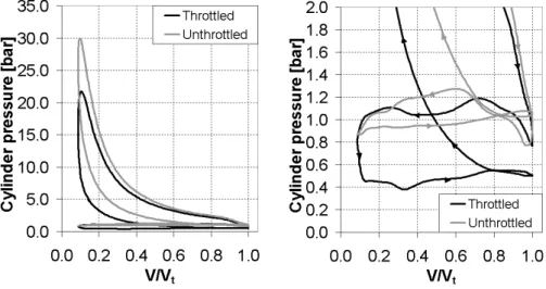
The limited λ-range calls for that the engine output, the torque, is modulated by controlling the amount of charge mass. The control is usually accomplished by throttling of the intake air and results in substantial gas exchange loss on part load as shown in Figure 11. The
Figure 10. Conversion in a three-way catalyst. Picture from [3].
A way to reduce the gas exchange loss is to allow the engine to operate lean. In order to achieve this the Gasoline Direct Injection, GDI, technology has in recent years come in focus. The principle is to inject the fuel directly into the combustion chamber. On part load the air motion, combustion chamber geometry and injection parameters are used to gather a fuel rich mixture in the vicinity of the spark plug. The rich mixture at the spark plug allows for an averagely lean mixture to be ignited, and consumed, thereby reducing the need for throttling which in turn reduces the gas exchange loss. With the GDI arrangement the compression ratio can be raised compared to a port injection case due to that the evaporation of the fuel within the cylinder lowers the charge temperature thereby reducing the knock tendency.
The drawback of the lean burn GDI technique is that the engine is operated lean while the fuel is burnt at close to stoichimetry conditions resulting in high NOx emissions. The fact that mixture is overall lean makes it impossible to reduce the NOx emission by mean of a three-way catalyst. Thereby lean NOx catalytic techniques are necessary. The GDI techniques should although avoid placing fuel in the land regions and thereby make it possible to avoid a portion of the CO and HC emission. In practice the benefit although has been shown to be small if any. Probably due to that the border of the rich mixture is hard to consume completely. On full load the injection is done in such a way that the charge is close to homogeneous thereby maximizing the power density. Another way to reduce the gas exchange loss, and maintain stoichimetric combustion, is to utilize a variable valve train. This technique has although this far not been widely spread but is put in production by BMW according to [7] and [8].
Recently, downsized engine concepts that features homogeneous GDI technology in the whole load range, supercharging and valve timing
gas exchange loss on part load. Supercharging is then used to reach the desired maximum power. Downsizing also reduces the friction losses that thereby increase the efficiency.
Diesel engine
Figure 12. Schematic Diesel combustion.
In the classical Diesel combustion system, a pure air charge is inhaled during the intake stroke and compressed during the compression stroke. At the end of the compression stroke the fuel is injected into the combustion chamber and hereby ignited by the compression heat. In the Diesel case the CR is not limited by knock and can therefore be raised substantial compared to an Otto engine. In fact the CR must be raised in order to ensure that the charge ignites during cold conditions. The compression ratio is usually chosen as high as possible, to allow for as high theoretical efficiency as possible, with respect to maximum allowable cylinder pressure and tolerances in the manufacturing. In contrast to the Otto engine this ignition mechanism is possible to realize in a very wide λ-range that make unthrottled operation possible. As a result the engine output is controlled by the injected fuel amount solely. Over the years different kind of injector nozzle arrangements and
combustion chamber geometries have come to use. During later years the technology has although converged to the Direct Injection, DI, system. Historically the DI system has excelled with better fuel economy than other arrangements, due to lower heat losses and fluid flow losses, but suffered in combustion speed and combustion noise. Due to this the DI system has historically predominately been used on larger engines where the fuel economy is of highest importance, combustion noise is of less importance and the engine speed is low. During the last fifteen years new injection systems have made it possible to overcome the noise and speed problem and use the DI technology also in small engine applications.
In the DI system, shown in Figure 12, the fuel is injected radial as a number of sprays in the combustion chamber. The fuel burns as a mixture controlled diffusion flame “on” these sprays at local λ ranging from very rich to very lean. Principally the rich regions produce soot that later in the combustion process event is mixed with “unused” air and oxidized further. In order to avoid too large soot emissions the overall mixture has to be lean and sufficient time for mixing and oxidation must be available. The fact that a lean charge is required leads to that the power density of a Diesel engine is lower than for an Otto engine. The NOx emission is mainly formed during two parts of the combustion process. First it is formed during the premixed combustion that is a result of the ignition delay and secondly as a result of the diffusion flame. The ignition delay is the time between that the injection is started and up until a positive heat release is apparent. The delay is caused by that the injected fuel must mix with the air, evaporate and undergo chemical pre-reaction steps before it ignites. The fuel that is injected during the delay time burns at the end of the delay very rapid as a premixed combustion. This rapid combustion causes a high combustion noise and significant amounts of NOx. The second source is the diffusion flame in which there
Compliance with the emission legislations this far has been achieved through engine internal optimization. In passenger car applications EGR have been used to lower the NOx emission. Likewise an oxidation catalyst is nowadays always deployed in passenger car applications to treat the CO and HC emission and to some extent lower the particulate emission. In order to comply with future sharpened NOx and particulate regulations lean NOx reduction and particulate traps are the likely road. HCCI engine
Figure 13. Schematic HCCI combustion.
The HCCI combustion system, shown in Figure 13, is a combination of the Otto and the Diesel engine. As in an Otto engine, the combustion charge is premixed. The mixing can either be done by injectors in the intake ports or by early direct injection as for example in [16]. The mixture is during the compression event exposed to high pressure and high temperature causing it to reach the point of ignition. Hereby the charge is ignited by the compression heat as in a Diesel engine.
The following combustion of the charge is neither Otto nor Diesel like. If the charge is homogeneous enough optical analyses in [17] show that the charge burns from a number of points in the combustion chamber. The combustion starts where heterogeneities in temperature and air/fuel ratio have created favorable conditions. During the combustion event new kernels are formed at places were the global pressure rise has lead to ignitable conditions.
The reactions that lead to the actual combustion are governed by temperature, pressure, concentrations of the participating species and time along the compression event. Different kinds of behavior can be seen during this stage. For certain fuels, mixture ranges, pressure ranges, and temperature ranges there might be a pre-reaction behavior called cool flame occurring as a step toward the actual combustion. The above dependencies result in a rather narrow operating window that makes timing of the combustion event, over a wide range of inlet conditions, one of the main obstacles to deal with when running an HCCI-engine. This is especially emphasized during transient conditions. As described above, the ignition is Diesel like thereby ensuring that lean mixtures can be ignited. Subsequently the engine can be operated unthrottled on part load, which results in a low gas exchange loss. In fact due to that the speed of the combustion is governed by chemical kinetics, and hereby strongly influenced by concentration of the reactive species, only lean mixtures are possible to burn with respect to limitations in pressure rise speed and pressure levels. As a result the power density is lower than for a Diesel and subsequently lower than for an Otto engine. The chemical kinetics also causes too lean mixtures to misfire. Another consequence of the combustion being controlled by chemical kinetics is that the combustion is much faster than the turbulent flame speed controlled Otto combustion and the mixing controlled Diesel
As the combustion takes place in the whole combustion chamber at lean conditions, the maximum temperature is moderate and thus result in very low NOx emissions. Charge that has reached down in narrow crevices will not burn and is one of the main contributors to the engine out HC emissions. The result is that the combustion system shows a, by comparison with a Diesel combustion system, relatively high engine out HC emissions and low combustion efficiency. These emissions are although in the range of raw Otto engine emission levels and should be possible to treat with an oxidation catalyst.
Pros and cons of HCCI combustion
From the previous sections it can be concluded that HCCI principally benefits in:
• Ultra low NOx and PM emission due to that the combustion takes place at overall lean conditions.
• High efficiency due to unthrottled operation and fast combustion. But suffers from:
• Low power density due to the requirement of a lean charge. • No direct way to time the combustion.
HISTORY
The history of HCCI can be said to have started as early as 1897 with the hot-bulb engine patent of Carl W. Weiss. It is although, as concluded in [18], difficult to say if one should regard the hot-bulb engines as HCCI-engines or as an early type of pre-chamber Diesel HCCI-engines. The hot-bulb principle seems although to be related to later days early injection HCCI concepts as the fuel is injected into a hot-bulb chamber and compressed with a, in comparison to a Diesel engine, low compression ratio, until it auto ignites. Example of a hot bulb layout is depicted in Figure 14.
Figure 14. Hot Bulb example. Picture from [18].
The history of HCCI research is although usually regarded to have started whit the Active Thermo-Atmosphere Combustion, ATAC, [19] and Toyota-Soken, TS, [20] works in 1979. The two Japanese publications seem to independent of each other have investigated two-stroke HCCI combustion concept. [20] used a two stroke horizontally opposed piston engine while [19] used a more ordinary two stroke configuration. The two papers have both noticed that it in some part load regions is possible to obtain a stable lean combustion with much lower cycle-to-cycle variations and radically reduced fuel consumption compared to the ordinary two stroke Otto systems. They have through the use of Schliren techniques concluded that the combustion takes place simultaneously in the whole combustion chamber without a distinct flame. They also concluded that the combustion could be achieved without a spark plug. In [19] an often-referred picture over the difference between Otto combustion, SI-combustion, and HCCI combustion were presented. The
Figure 15. Principle difference between Otto, SI, and HCCI. Picture from [19].
The same combustion mode that was discovered in [19] and [20] were in 1983 reproduced in a four-stroke engine [21]. The process was named Compression-Ignited Homogeneous Charge, CIHC. In 1989 an engine layout based on a four-stoke HCCI process on low load and a standard Otto process on high loads was presented in [22]. The advantage of this approach lays in the possibility of reduced fuel consumption without being forced to use lean NOx reduction catalytic techniques.
CONCEPTS
Since the early works, a number of HCCI-based combustion concepts have been investigated. In recent years the published research has increased tremendously with research activities ongoing worldwide. Of particular interest from a Swedish point of view is that Lund Institute of Technology has emerged as one of the world leading HCCI laboratories. The increased research activity has diversified the world of HCCI and a number of HCCI concepts have been presented. The concepts mainly differ in the way the fuel is introduced, port injection or DI, what fuel that is used, and how the combustion timing is controlled. In the following some often-referred abbreviations will be clarified. The following is not
intended to be a complete history but merely an example of how diversified the HCCI field looks as of today.
Controlled Auto Ignition, CAI, is another name for ATAC/TS combustion that appears in the two-stroke world. It is for instance used in [23]. It also appears in papers, [6] and [24] for instance, where high residual amounts to achieve HCCI combustion in four-stroke applications are used.
Activated Radical, AR, is another name for the ATAC/TS combustion used in [25]. In the work referred above a variable exhaust port is used to control the AR-mode.
Premixed Charge Compression Ignition, PCCI, is used by Toyota in [26] as a name for a HCCI combustion concept that is based on port injection of gasoline. Many regard the name PCCI as a more suitable family name than HCCI as one never is absolutely sure that a mixture is homogeneous in all respects.
Compression and Spark Ignition, CSI, is a concept name presented by AVL and described in [24]. The concept is a development of the idea presented in [22]. The main difference is that this concept uses direct injection of the fuel. The concept is in fact a lean GDI concept that utilizes a HCCI mode for the middle load range. The HCCI combustion timing is controlled by controlling the amount of residuals in the cylinder from the previous combustion cycle by means of a variable valve timing. The high load is covered by a homogeneous spark ignited lambda one mode while the extreme low load is covered by a spark ignited GDI mode. The later is done to ensure ignition of the charge even under extremely diluted conditions. The CSI-concept is said to comply with future emission standards without DeNOx catalyst and special fuel demands. A great effort is put on making the concept ready for
PREmixed lean Diesel Combustion, PREDIC, is a concept that utilizes very early diesel injection described in [27] and [28]. The idea is to inject diesel fuel long before CTDC and ignite the charge by the compression heat. Injection starting at -170 CAD had been investigated. Different injection nozzle arrangements have been investigated which aims at stratifying the charge and avoid wall wetting. Examples of two nozzle arrangements are shown in Figure 16.
Figure 16. Different injection nozzle arrangement investigated in [27] and [28]. Picture from [28].
Homogeneous Charge compression ignition Diesel Combustion, HCDC, utilizes port injection as well as direct injection. The principle, presented in [29] and [30], is that a homogenous charge, which is created by the port injectors, is ignited by a direct injection close to TDC. If the fuel amount that is direct injected is small compared to the port-injected amount, the combustion will be HCCI like.
Modulated Kinetics, MK, is the name used by Nissan of their Diesel concept described in [31] and [32]. The system utilizes high EGR amounts, high swirl levels and extremely late DI diesel injection in order to inject the fuel during the ignition delay. The fuel is during the delay mixed with the gas charge and forms a “homogeneous” mixture that allows a homogeneous combustion mode to be achieved. The combustion system is utilized in a Nissan production engine, YD25, on low loads.
Another concept that recently has been proposed in [33] is an engine that utilizes a HCCI combustion concept on low loads and a Diesel combustion concept for high load. The aim with the combustion concept combination is to address the Diesel after treatment issue with low exhaust gas temperature on low load that leads to low after treatment conversion efficiencies. The idea is to utilize the HCCI mode, which does not produce NOx and particles, in these areas and utilizes the Diesel mode on high load points, which does not suffer from low exhaust temperatures, in order to achieve normal Diesel engine power density. COMBUSTION SIMULATION
The pure HCCI combustion process is primarily controlled by chemical kinetics. This leads to that in order to understand the ignition and combustion mechanism, detailed knowledge of the chemical kinetics is an important ingredient. As a result, detailed simulation of the chemical kinetics is an important research area. The chemical kinetics simulation is very computer intensive why reduced reaction mechanisms and simplified geometric representation are used.
Examples of methods and results can be collected from references [34] and [35]. In [34] a method that utilizes the temperature from a CFD simulation of the flow field as base for the temperature in the simplified
complexity of the simulation, the well-defined fuel ISO-octane is considered. In [35], the temperature distribution is collected from an engine cycle simulation. [35] also suggests a reaction mechanism for gasoline.
CONTROL
Timing of the SOC of HCCI combustion is for a number of reasons crucial for an HCCI engine. If the combustion occurs to early, high pressure rise speed, which is related to combustion noise, and high maximum pressure will result. If on the other hand the combustion occurs too late the charge will in the limit misfire and cause large HC-emission and no work output. Figure 17 shows an example of a measured cylinder pressure trace and an estimated cylinder temperature trace for a typical engine cycle. The figure also shows the estimated isentropic pressure that would have resulted in the absence of combustion. Figure 18 shows the heat release that is occurring in Figure 17 and that cause the rise in pressure above the isentropic pressure. The engine is operated at 1000 rpm resulting in that the whole cycle, two crankshaft revolutions, last for 120 ms. In this case the combustion is occurring close to CTDC.
As a measure of the combustion timing is often, due to detection reasons, CA50 chosen as exemplified in [36] [37]. The possible CA50 timing window varies with engine operating point making specific numbers hard to give. For the engine in this work, operated in the present load and speed range without cooled EGR the possible timing window generally is between 3 and 8 CAD after CTDC. Although, for each operated point the timing requirements are that CA50 shall be timed in the range of some CAD.
Figure 17. Measured cylinder pressure and estimated cylinder temperature for the HCCI engine according to Table 2 operated at 1000 rpm, an inlet pressure of 1.5 bar absolute, inlet temperature of 60 °C and at an netIMEP of 6.0 bar. Also shown is the estimated isentropic pressure that would have occurred during a motored cycle. The estimated parameters are calculated during the part of the cycle when all engine valves are closed.
Rough SOC model
Over time a number of different approaches to phase the combustion have been proposed that will be described in the following. In order to explain how they affect SOC a rough SOC model is presented.
In some situations a course approach is desirable to explain the basic mechanisms that governs SOC as a chemical kinetics simulation is very complex and computer intensive. In order to get a rough understanding of the ignition mechanism the knock-integral-method described in [38] can be used. The method has primarily been used to predict knock in Otto engines and ignition delay in Diesel engines [2]. The use for HCCI-combustion has been proposed in [39], [40] and [41]. In the attached Paper I and [42] it is verified to describe SOC of HCCI combustion in narrow regions. Work on how to broaden the valid region can be found in [43], [44] and the attached Paper V. Other approaches for rough SOC models can be found in [45].
The basic in the method is that the ignition delay time, τ, can be estimated through an Arrhenius correlation.
T B n
*
e
p
*
A
−=
τ
(14)
A, n and B - Positive coefficients. p - Pressure
T - Temperature
If pressure and temperature varies during the ignition delay, as is the case during the compression event, the time to ignition can be estimated in accordance with Livengood and Wu as
( )
s
ds
1
1
SOC t IVC t IVC t=
∫
+τ
(15)
τ- Ignition delaytIVC- Time at inlet valve closure
tIVC+ tsoc- Corresponds to the time when enough radicals are present to ignite the charge
As can be seen in Equations 14 and 15 SOC is affected by the pressure and temperature during the compression event. As a result SOC is affected by the boundary conditions of the combustion chamber. For instance the pressure and temperature during the compression event is governed by the inlet pressure, inlet temperature, exhaust pressure, exhaust temperature and combustion chamber wall temperature. The engine speed and injection timing, in a DI case, governs the time during the compression event. Also, the coefficients in Equation 14 are not fixed but rather functions of the charge state. The result is that apart from pressure and temperature it can be argued that the fuel load, fuel concentration, and the trapped residual mass is affecting the ignition. The above dependencies result in a narrow combustion-timing window. This makes combustion-timing control, over a wide range of engine conditions, one of the main obstacles to deal with when running an HCCI-engine. This is especially emphasized during transient conditions. Control of two-stroke
The early two-stoke work [19] used optimization of the transfer port to widen the HCCI operational area. In [23] it has been shown that it is possible to control the combustion by aid of valves in the transfer ports.
Figure 19. Honda exhaust port valve. Picture from [46].
In [25] and [46] a variable exhaust port is used to control the HCCI combustion. In [46] it is concluded that the most important factor determining the occurrence of HCCI combustion is the pressure and temperature of the residual gas when the exhaust port closes. It is also concluded that a throttle valve in the exhaust port can be utilized to control the pressure and temperature. The arrangement has come to use in a production prototype where the electronic engine control unit controls the throttle valve, which is actuated by an electrical servomotor. Figure 19 depicts the exhaust port valve.
Control of four-stroke
In [47] a method called thermal management was analyzed through simulation. The idea was to use exhaust energy to heat the intake charge. In Figure 20 the principle concept is shown.
Figure 20. Schematic of thermal management suggested in [47]. Picture from [47].
In the PREDIC concepts, [27] and [28], the combustion phasing is affected by when the injection takes place. As a result it is possible to control the combustion phasing by means of the injection timing. The phenomena is although more complex than revealed by the “Rough SOC”-model, Equation 14 and 15, as injection timing also affects the mixing, stratification, of the charge. The result is that in some cases later injection timing result in an earlier combustion compared to earlier injection timing.
determined as a result of the ratio between the two fuels. The results showed that reasonably fast transient behavior could be achieved. In [37] a break thermal efficiency of 41.2 % and a load of 16 bar BMEP were achieved with the same control structure.
In the attached Paper I to V, [6], [48], [49], [50] and [51] it has been shown that the combustion can be controlled by capturing hot residual gases by aid of modified or flexible valve trains over a wide range of operating conditions. In Paper I to V, [50] and [51] the combustion has been timed in a feedback loop with the aid of variable valve timings. The effect of variable valve timings has for example been investigated through simulation in [52] and [53].
In [54] and [55] the combustion were timed with variable compression ratio and a variable fuel amount in a five-cylinder engine. The fact that the compression ratio is a global control parameter for the whole engine leads to the strategy to balance cylinder-to-cylinder differences with the fuel load. The principle for the variable CR used in [54] and [55] is shown in Figure 21.
Figure 21. The principle for the variable compression ratio in the SAAB SVC engine concept used in [54]. Picture from [54].
Control through valve timings in detail
In principle there are two ways to affect the combustion timing by variable valve timings. The first way is to increase the temperature of the charge, here exemplified by what in the following is called the Overlap-method, and the second way is to affect the effective CR, here called the IVC-method. The Overlap-method is also known under other names such as recompression or negative overlap.
The Overlap-method has for example been reported in [6], [48], [49] and [56]. As exemplified in Figure 22 and 23, an increased negative overlap, that increases the amount of trapped residuals, leads to earlier phased combustion. The cause for this behavior is that the residual gas, i.e. internal EGR that is trapped from the previous cycle is hot and thereby promoting reactions as described by Equations 14 and 15.
In [6], [50] and [51] an alternative method to the Overlap-method has been investigated. The idea is to use valve timing similar to those exemplified in Figure 4 and raise the temperature of the combustion charge by reopening, or delayed closing, of the exhaust valves. By doing so the exhaust valve is open during a part of the intake stroke and a mixture of fresh charge and hot burnt gases is prepared for the on coming combustion cycle. The main benefit is said to be lowered heat transfer losses compared to the Overlap-method.
The strategy referred to as the IVC-method is described in Figure 24 and 25. The strategy works by affecting the effective compression ratio thereby affecting pressure, trapped mass, and temperature during the compression event. This will according to Equations 14 and 15 lead to a shorter/longer ignition delay. A lowering of the effective compression ratio is in Figure 24 and 25 achieved by closing the inlet valve later during the compression stroke.
Figure 22. Heat releases, from engine tests, for the two different negative overlap that are shown in Figure 23.
Figure 24. Heat releases, from engine tests, for the two different inlet valve closures that are shown in Figure 25.
By examining Figures 22 to 25 one can be lead to believe that the Overlap-method is a weak control strategy, requiring a large amount overlap change to impose a certain combustion timing change, and that the IVC-method is a strong control strategy, requiring a small amount of IVC change to impose a certain combustion timing change. That conclusion is correct for these particular valve timings but should not be generalized. The strong behavior of the IVC-method is in this case a consequence of the fact the IVC range is placed in the crank angle region where the piston velocity peaks. The result is that an IVC change results in a relatively large change in the effective compression ratio. Feedback signal
The task to time the combustion correctly requires feedback from the combustion chamber in some way or other. The most direct way of achieving this is by in-cylinder pressure measurements. This method is expensive and not practical to realize in series production at the moment. A drive to make the whole engine control system cylinder pressure based [57], [58] and [59] makes small/cheap in-cylinder pressure transducers foreseeable in the future. Recently, glow plug based cylinder pressure sensors aimed for series production have been made public [60]. The analysis of the cylinder pressure can be done by direct heat release analysis, as for example in [36], or less computer expensive based on the Rassweiler and Withrow relationship, described in [61], as in Paper I, [57] and [58]. Another way to achieve direct in-cylinder feedback is through an ion-current transducer as suggested in [24] and [50]. The ion-current has been evaluated for HCCI in [62] and [63] and used as feedback for control in [64].
The combustion timing signal displays in general an cycle-to-cycle variation as shown for example in [65] were an analyze of the cycle-to-cycle variation has been conducted for the engine used in this work with data according to Table 2. In [65] auto correlation and effect spectrum analyze of the signal were done showing that the variation could be
regarded as white noise. The statistical properties of the white noise were found to vary some with engine operating point.
Dynamic properties
Analyze of the dynamic properties, through system identification or physical modeling, of the HCCI combustion timing has been done in numerous publications. For instance in [65], [66], [67] and [68]. The conclusion is that low order models describe the dynamics.
Transient
Real transient capabilities has for example been shown in the attached Paper I to V, [36], [37], [51] and [55]. In [36] and [37] the control structure was a gain scheduled PID-controller while it Paper I to IV was a fixed parameter PI controller. The controlled variable was CA50.
Other control structures have been utilized in for example [69], [70], [71] and [72]. In [69] an LQG-type structure were used, based on identified dynamic models, for control of the combustion timing. The control was based on the dual fuel approach. The identified models in [69] were concluded to be of low order. In [70] has the same model approach as in [69] been used but the control parameter is IVC and the control performance using PID, LQG and MPC control structures are evaluated. Several works has presented multi variable control. [71] uses models based on physical modeling and aims at achieving multi variable control. The control is performed with an LQR-structure and is essentially a load control when using a re-induction valve timing strategy. Predetermined valve-timing relations achieve the combustion timing. A similar control task was performed in [72]. Here the control structure was based on static calibrations and dynamic compensations. The controller class was not clearly revealed. In [73] a controller that utilizes an MPC-structure is
Mode switch
If the engine is supposed to work as a HCCI engine on low loads and as an Otto engine on higher loads, another very important control issue arises. The task in these concepts is to make a smooth and safe transition from one combustion mode to another. Attempts to control the mode switch has been done in for example [51], [74] and [75]. The results show that the transition from Otto, SI, to HCCI is harder to conduct than the reversed transition. Figure 26 shows example of an Otto to HCCI switch.
Figure 26. Switching from SI, Otto, to HCCI combustion. Picture from [51].
The reason according to [51], is that the Otto operation usually has much higher exhaust temperatures than HCCI operation, which result in that
the first HCCI cycle ignites far to early causing an unfavorable pressure rise speed. It is in [51] concluded that the mode switch is a challenging tasks for an engine control system and that a powerful control algorithm is necessary.
ENGINE CONTROL
Engine control systems of today handle a great number of tasks. Not only the engine is to be controlled but also the communication with other systems has to be ensured. As example of other systems one can mention vehicle stability systems, cruise control and transmission. An input-output list can, according to [3], look as follows for a modern engine management system.
Input: Knock sensor, transmission control interface, traction control interface, lambda sensor, sensors for ignition and injection data.
Output: Ignition, idle speed actuator, fuel pump and injectors, camshaft, diagnosis, EGR valve, canister purge, CAN.
In the following the aim is to focus on the “engine close” tasks fuel and combustion control. Generally speaking the “engine close” control of an Otto-engine requires more precision than the “engine close” control of a Diesel engine. The reason is that an Otto-engine must operate in a narrow λ-window, especially if a three-way catalyst is used, and the fact that throttling of the intake controls the engine output, the torque. As a result the Otto-Engine is utilizing a feedback control for fuel metering. In some Otto-engines, engines with high CR and boosted engines, also the ignition timing is controlled in a feedback loop in order to get best efficiency and avoid knocking combustion. The “engine close” control of the Diesel engine does not have the same precision requirements and can as a consequence be based on maps.
![Table 1. Emission levels for Heavy Duty truck engines as stated in [1].](https://thumb-eu.123doks.com/thumbv2/5dokorg/4954131.136233/8.892.207.722.294.610/table-emission-levels-heavy-duty-truck-engines-stated.webp)
![Figure 2. Schematic of the four-stroke process. Picture from [2].](https://thumb-eu.123doks.com/thumbv2/5dokorg/4954131.136233/12.892.244.693.352.660/figure-schematic-stroke-process-picture.webp)
![Figure 3. Schematic of the two-stroke process. Picture from [2].](https://thumb-eu.123doks.com/thumbv2/5dokorg/4954131.136233/14.892.222.698.170.549/figure-schematic-stroke-process-picture.webp)
![Figure 5. Different types of valve trains. Picture from [3].](https://thumb-eu.123doks.com/thumbv2/5dokorg/4954131.136233/17.892.228.697.231.400/figure-different-types-valve-trains-picture.webp)
![Figure 6. BMW Valvetronic mechanism. Picture from [7].](https://thumb-eu.123doks.com/thumbv2/5dokorg/4954131.136233/18.892.219.567.161.567/figure-bmw-valvetronic-mechanism-picture.webp)
![Figure 8. Principle three-way catalyst. Picture from [14].](https://thumb-eu.123doks.com/thumbv2/5dokorg/4954131.136233/28.892.222.703.394.594/figure-principle-way-catalyst-picture.webp)