Mälardalen University, Västerås
School of Innovation, Design and Engineering
MASTER OF SCIENCE THESIS
ProCom middleware
Jiří Kunčar
jiri.kuncar@gmail.comSupervisors: Etienne Borde, Jan Carlson
Examiner: Jan Carlson
September 2011
2 This thesis would not be possible without the help of my supervisor Etienne Borde. I would like to thank Jan Carlson for his advice and invaluable input to my research. To Rafia Inam for her kind advice and introduction to the embedded systems development. And finally to Tomáš Bureš for giving me the opportunity to write this thesis.
I hereby declare that I wrote this thesis myself using the referenced sources only. I also agree with lending and publishing of this thesis.
Abstract
The goal of this thesis is to develop and implement parts of a middleware that provides necessary support for the execution of ProCom components on top of the real-time operat-ing system FreeRTOS. ProCom is a component model for embedded systems developed at Mälardalen University.
The primary problem is finding an appropriate balance between the level of abstraction and thoughtful utilization of system resources in embedded devices. The defined target plat-form has limitations in comparison to general purpose computer. These include constraints in available resources such as memory, CPU or bandwidth together with strict requirements in terms of worst-case response time and reliability. We have to also face the problem of limited debugging facilities or their complete absence.
Another part of the challenge has been to create the initial design of middleware interface functions that need to be integrated with the layered ProCom model including support for transparent communication within one node or between nodes. We try to uncover potentially hidden problems related to the communication and creation of templates for the code synthe-sis. This especially means that we should identify and provide a list of the most important information needed to create a model of physical platforms and the subsequent allocation model, which allows assignment of ProCom components to the individual nodes of physical platform.
In this project, we have examined differences between several real-time and non real-time operating systems. We focus on finding a common subset of core functions that the system must support in order to ensure adequate support for running designed components. We have also identified and tested the suitable libraries to support different types of communication especially TCP/IP. However, we are keenly aware of the limitations of used communication types for analysis of the behavior of real-time systems.
This report describes the design and implementation of ProCom middleware. The data structures and methods used both in task management and inter-subsystem communication are described. An example how to generate code using the middleware is also included in this report.
Contents
1 Introduction 7
1.1 Problems Definition . . . 8
1.2 Benefits of the Implementation . . . 9
1.3 Outline of the Thesis . . . 9
2 Background 10 2.1 Real-time Embedded Systems . . . 10
2.2 Middleware . . . 11
2.3 Component Based Development . . . 12
2.4 PROGRESS and the ProCom Component Model . . . 13
2.5 Development process . . . 14
2.6 Technological Background . . . 16
3 Modelling and Comunication Design 20 3.1 Physical Nodes . . . 21
3.2 Virtual Nodes . . . 22
3.3 Channels . . . 22
4 The ProCom Middleware 25 4.1 Platform Abstraction Layer . . . 25
4.2 API proposal . . . 27
4.3 Data structures . . . 30
5 Message Communication 35 5.1 Message Sending . . . 35
5.2 Message Receiving . . . 38
5.3 Connection Reliability and Message Delivery Confirmation . . . 40
6 Application Example 42 6.1 Components . . . 42 6.2 Virtual Nodes . . . 43 6.3 Physical Nodes . . . 45 6.4 Code Structure . . . 48 4
CONTENTS 5 7 Related Work 49 7.1 AUTOSAR . . . 49 7.2 SOFA HI . . . 50 7.3 MyCCM-HI . . . 50 7.4 RubusCMv3 . . . 51 7.5 Similar Models . . . 51
8 Conclusion and Future Work 52 A API Documentation 57 A.1 Functions . . . 57
A.2 Macros . . . 58
B How to build own application 60 B.1 Prerequisites . . . 60
B.2 Obtaining Source Code . . . 61
B.3 Compilation . . . 61
List of Figures
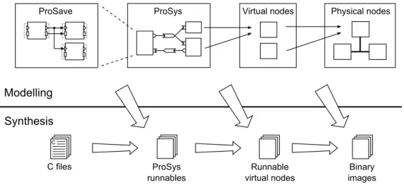
2.1 Overview of deployment modeling and synthesis [3] . . . 15
2.2 AVR Dragon and EVK1100 Evaluation Board . . . 18
3.1 Single channel design . . . 23
3.2 Local and network connection . . . 23
3.3 Two channels . . . 23
3.4 Two way connection . . . 23
3.5 Two channels (another layout) . . . 24
3.6 Channel collocation . . . 24
4.1 Message port structure initialization . . . 31
5.1 Atomic message send . . . 36
5.2 Independent trigger and data writing . . . 36
5.3 Multiple writers . . . 37
5.4 Two readers of same message . . . 39
5.5 Periodic and sporadic tasks read the same message . . . 40
5.6 Only periodic tasks . . . 40
6.1 Sender . . . 42
6.2 Forwarder . . . 42
6.3 Receiver . . . 42
6.4 Virtual node connection design . . . 43
6.5 Local communication . . . 45
6.6 Ethernet communication . . . 46
6.7 Serial communication . . . 47
C.1 Creating new example project . . . 64
C.2 Select example project . . . 65
C.3 Choosing name and location . . . 65
C.4 Project Explorer . . . 66
Chapter 1
Introduction
There is a great deal of interest in communication nowadays. It is here to help us to solve the problems faster and more efficiently. But to do so we need to break the language barriers, understand each other and deliver the messages to the right listeners.
Communication is widespread and takes many forms. Not only people communicate, but also (even thought we do not realize) in our common life computers in offices, machines and their parts — everything communicates with each other and meets with similar problems. Progression in this area is evident every day, especially in the field of industry and it puts emphasis on communication time requirements and efficiency. This general trend is seen for example in automotive industry, where the complexity of electronic components (such as engine control, anti-lock braking system, electronic stability control, collision avoidance system, parking assistants, etc.) is growing exponentially, according to Bureš et al. [1].
Besides, new functionalities are developed and needed to be integrated into current sys-tems. Component Based Software Engineering (CBSE) brings many improvements to de-veloping software for distributed real-time embedded systems by reducing the complexity, organizing the division of the functionality into independent subsystems often developed by different suppliers and enabling easier reuse of once developed and tested components.
The component model used in this thesis is developed within a large research vision called Progress which aims at providing theories, methods and tools for the development of real-time embedded systems [2]. In order to allow the automatic code generation, we implement and give precise enough description of the functional blocks needed for components code integration in order to produce executable binaries. The specific code must be included to provide execution support and enable inter-component communication independently on the underlying platform.
This thesis starts with description of the problems originated in the development of a mid-dleware that provides necessary support for the execution of ProCom1 components on
hetero-geneous hardware and operating systems of embedded devices. The main focus is dedicated to support of the transparent communication between these devices.
1
Progress component model
Problems Definition 8
1.1
Problems Definition
Creation of a wrapper code for the integration of the software components used in Distributed Real-Time Embedded System (DRTES) faces several conflicting requirements. In addition, the semantics of the ProCom model and the Progress deployment process designate a set of requirements on the runtime environment. There are also several demands on the resulting code structure and runtime library. All requirements are closely described in [11], but only some of them are related to the thesis.
To create as much as possible accurate design of the middleware it is necessary to take into account the significant differences between operating systems and hardware on which the middleware is supposed to work. Moreover, there is a serious concern and need for its integration into the development environment and support for as easy as possible code generation components using this middleware. We also need to consider difficulties of reusing existing code in different usage contexts.
Particularly with regard to the reusability of the components, the knowledge of the inner structure of the entire system should be put outside the component code scope. Referring to the communication the knowledge of receivers should not be included in generated com-ponent code.
The developed middleware should allow transparent reallocation of components (or tested set of components) to take advantage of CBSE approach. It means that we should be able reuse the code on different platform with any or minimal modifications. The structure of the components should be easily generated from the model of components. However, the runtime library code can be more complex. The complexity of the runtime library code is not a problem in this case, because there is time to test and validate it. It must be clearly defined for every individual section of the final code if it is automatically generated according to component model, or whether it is part of the runtime library.
Futuremore, the middleware should also provide access to the shared system resources to avoid conflicts during accessing them. However, there is a contradiction between an effective utilization of resources and re-usability that inhibits to fulfill the requirement. The most thoroughly discussed set of requirement concerns communication.
Support for channels with more than one sender and reader is a preliminary step to build model of communication between components. The real-time analysis entails the need to ensure that the channel topology (or its change during design process) can not affect analysis results by changing behavior and characteristic of a component within performing operation adherent to the channel communication.
From a modeling point of view there are various possibilities how the components can be associated to message ports and use asynchronous message communication. The middleware has to fulfill rigorously the defined semantics of message passing. We should also not overlook to ensure binary compatibility of sending data between different platforms. Typical example of such a problem is a big and little endian byte order (description is available in [21]).
Finally, we would like to remember the problem with limited resources and real-time requirements that needs to be considered to make predictable system with time and event triggered tasks.
Benefits of the Implementation 9
1.2
Benefits of the Implementation
With our developed middleware we are able to compose previously created components into monolithic firmware for the defined platforms. Since composition is made in design time under the ProCom component model, therefore we can perform optimization of components and connections between components, which can be replaced by direct function call.
The middleware provides functionality covering most of the features, that the developer of the synthesis mechanism may require. Several additional improvements for saving resources were implemented. For example we made transparent sharing of the physical connection among several components on the same device possible. However, developer of the system does not have to think about these problems at the beginning of development process and he can focus on right design of his application, instead of developing underlying supporting functionality because of separation of modeling and deployment phases.
Building and analyzing of the system become easier, because middleware can be more thoroughly tested and analyzed based on well know or measured properties at different plat-forms. It also helps with separation of software and hardware design, which we hope to expand to the independent use and allocation of not only software but also hardware com-ponent in future.
The middleware is easily extensible to support new hardware for different communication media or other operating system and as an extra benefit it is possible to use the library outside context of the ProCom model. Developers can focus only on creating functional code and the library solves the communication and task portability for them. Finally, the middleware can be distributed either with full source codes or even in pre-compiled form for supported operation systems.
1.3
Outline of the Thesis
The remaining part of this thesis comprises these chapters: Chapter 2 gives definitions and an overview of the technologies used when developing software for the distributed real-time embedded systems. The design and structure of middleware layers are discussed in Chapter 3. Chapter 4 presents architecture of the ProCom runtime environment and introduce the API2.
The description of communication process is concisely introduced in Chapter 5. Chapter 6 gives an example of how our middleware can be used in developing component systems that use different types of connection for message communication. Related projects are presented in Chapter 7, and Chapter 8 concludes the report.
Chapter 2
Background
In this chapter, we start with several definitions of the real-time and embedded systems, and the middleware. Following part describes component based development and com-ponent framework for system modeling according to the ProCom model. Essential parts of the Progress project and the ProCom component model are described in section 2.4 followed by technological background about operating systems, libraries and hardware sup-ported by current version of the middleware. Last parts of the technical section consist of a short introduction to the development environment (AVR32 Studio1) and presentation
of another tested experimental hardware.
2.1
Real-time Embedded Systems
In this section, the definitions of real-time and embedded systems will be briefly introduced. The various demands and the most important properties of these systems are presented and understanding them is important for comprehension of decisions made during the work.
2.1.1
Embedded Systems
Electronic devices containing microprocessors are almost everywhere around us. In fact, only about one percent of them is in personal-computers (PC) including laptops [15]. The rest are included in many common devices and helps people with simple daily tasks such as preparation of lunches in microwaves or doing laundry in the washing machines. Users may not even notice the existence of the processor and software in the device that they are using. The microprocessors are also part of some larger and complex systems in automotive industry. Embedded systems are computer systems that are part of larger systems and they perform some of the requirements of these systems [5]. They are designed to perform their task in very efficient way, mostly (partially) independent of human intervention. The device may be extended or connected with additional mechanical parts or sensors, e.g. detection of closed-door in a car, wheel rotation or distance sensors, to be able interact with the environment
1Available at http://www.atmel.com/dyn/products/tools_card.asp?tool_id=2725
Middleware 11 where is located. In larger systems that are composed of many smaller units, effective and reliable communication is the integral part of the system.
Embedded systems are closely related to real-time systems (discussed below) often in safety-critical applications, e.g., transportation vehicles, where they take care of all different kinds of tasks under difficult environmental conditions such as dust, vibration, electromagnetic interference, etc.
2.1.2
Real-time Systems
A real-time system is a computing system in which correctness depends not only on the logical results of the computations, but also on physical instant at which the system produces the correct results [13]. Another possible definition found in [12] describes a real-time system as a set of concurrent programs called tasks that have to respond to an internal or external event in a determined time period. The time when the period ends is called deadline.
A real-time system can be classified as a hard real-time system if the result must be produced before deadline otherwise there is no value to the computation. The extreme of missed deadline may have a serious consequences to the system or its user. We can describe the situation using examples with the collision avoidance system or engine control of a car. In the first example, the system could be incapable to stop the car and avoid a collision, because a computation of distance and speed can take more time than is expected. When the ignition is delayed due to missed deadline of engine control task, irreversible engine damage can occur. However, in soft real-time systems it is acceptable that a task deadline is missed with no serious threat or damage. For instance while an audio or video stream is being listened, missing some deadlines causes a quality degradation of the sound.
An important requirement for many real-time systems is to achieve predictability. In hard-real time systems, it is also necessary to predict the peak-load performance and avoid missing predefined deadline. The easiest way how the system can meet deadlines of all concurrent time-critical tasks is to use a static scheduling. The run-time overhead is very small, but all scheduling decisions have to be made at compile time. However, if the system has to adaptively react to non-regular external events, than the static scheduler is not suitable. Dynamic scheduler is more flexible, although it can incur nontrivial system overhead and requires detailed system analysis to ensure desired behavior.
2.2
Middleware
A middleware is, in our case, the software layer that lies between operating systems and soft-ware components that can be located on different devices connected by network. It consists of a set of services that allows transparent inter-process communication based on messages within one or between several nodes. Middleware can help to manage complexity and hetero-geneity of the underlying operating systems and hardware and also it facilitates using multiple network technologies. It tends to provide consistent and integrated distributed programming environment.
Component Based Development 12 Through indisputable advantages, there are also disadvantages in terms of performance degradation, that must be taken into account on systems with limited resources. A higher level of abstraction usually increases code re-usability, but it can decrease efficiency in using resources.
2.3
Component Based Development
While demands and expectations on functionality included in machines around us (such as refrigerators, televisions, cell phones and cars) are growing, developers have to deal with higher complexity of the software driving the devices. A possible solution lies in dividing software into smaller independent units — components. This type of development is called component based development (CBD) and it is described more precisely in [4].
The advantage of such a division is in the possibility to develop the units independently and reuse or compose them, thanks to well defined interfaces of each unit. Developed, analyzed and tested components can be stored in a software repository prepared for a future use. Furthermore, these components can be pre-compiled or shared among developer groups. Therefore increasing reliability and reduced development time can potentially be achieved.
However, the CBD approach has also several problems. Most of them come from desired component properties described in [20]: isolation (a component is an atomic deployable unit, that can be run independently), composability (a new component can be constructed from existing hierarchically structured and interconnected components) and opaqueness (a knowl-edge of component implementation is not necessary for using component – only the interface). The first problem is connected with a need of isolated and reusable code in components. This can lead to suboptimal utilization of resources. A strict decomposition into small compo-nents and re-composition causes an overhead but on the other hand using too big compocompo-nents does not solve the complexity problem mentioned at the beginning of this section. Opaque-ness of component implementation can bring a problem when changing the implementation. Therefore the specification of the component model should be complete and accurate. Devel-opment of a component system can be more time-consuming than creating the application in the usual way. Especially the first time, since it requires to adopt the component semantics. Nevertheless, the appropriate framework and tools should decrease the needed time.
2.3.1
Component Framework
With CBD, developers can build systems by assembling existing components. To take more advantage from CBD, a software component framework automatically generates the non-functional code, i.e., the “glue” that plugs together individual components. Such a frame-work has been developed within the Progress project. The purpose of ProCom Integrated Development Environment ( Pride2) is to support design, analysis, and realization of
compo-nents and component-based systems using different tools integrated in a common environment [10]. The implementation of the ProCom middleware created as a part of the thesis should
PROGRESS and the ProCom Component Model 13 help when generating “glue” code connecting components and runtime support for different execution platforms with the code generated by PRIDE.
2.4
PROGRESS and the ProCom Component Model
This thesis is a part of the larger research vision called Progress, which is the Swedish national research center for predictable development of embedded systems. In this section a brief overview of the vision is introduced as it is described in [2].
The overall goal of the Progress project is to cover the whole development process start-ing from a vague specification at the beginnstart-ing to the final specification and implementation including reliability predictions, analysis of functional compliance, timing analysis and re-source usage analysis [11]. The ProCom component model has been introduced as one part of the PROGRESS project to be used mostly on real-time embedded systems. It consists of two different (but related) layers which help to solve the problem with the right level of component granularity. The larger units are using message passing. At more fine-grained level, the information about timing and synchronization requirements are known and the communication within one subsystem can be much more simple and optimized.
The lower level, called ProSave, aims to design functional components, which could be hierarchically structured and used as composite units. These components are passive and the communication on the ProSave level is based on pipe-and-filters paradigm [2] in contrast of ProSys layer, where the components compose a collection of concurrent, communicating sub-systems. The communication is mediated by sending messages through channels connecting message ports.
ProCom has also particular elements that enable communication between the ProSave and ProSys layers. The clocks generate periodic triggers and message ports create mappings between message passing and trigger or data communication on ProSave level.
More detailed information about ProSys and ProSave layers are included in 2.4.1 and 2.4.2, respectively. The software development and deployment according to the Progress vision are described in 2.5.
2.4.1
ProSys
As mentioned in the beginning of this section, ProSys models a system as a collection of sub-systems. The subsystems can be composite — contain one or more interconnected ProSys subsystems, or primitive — usually build from a set of ProSave components. In the final system a ProSys subsystem is represented by set of tasks, message ports (input and output) and parameters required for execution. If the composite ProSys subsystem contains any local communication between its subsystems then it is statically resolved during the syn-thesis and it is not visible outside of the subsystem. This simplify middleware concept of the communication part.
Communication on this level is possible only through the asynchronous message channels connecting message ports. Each channel is typed and only a message port that sends or
Development process 14 receives that type can be connected to the channel. There are no limitations to channel complexity (it is possible to use channels with more that one writer and reader), but it is very important to say, that no dynamic changes of the channel structure or subsystems are allowed after deployment. The support of transparent network communication is also needed, because subsystems are reusable and can be mapped to different nodes.
2.4.2
ProSave
ProSave is the lowest layer in ProCom using several modeling constructs. Services consist of one input port group and one or more output port groups. Each group consists of one trigger port and zero or more data ports.
For full understanding of the thesis it is not necessary to know all parts from which the ProSave component can be composed. The bindings to the developed library is very simple. ProSave component routines are represented by C functions and corresponding data structure. The activation connection with ProSys layer can be created in two different ways. The first one is done by a clock event with defined period and the other trigger can be an incoming message on an associated input message port.
2.5
Development process
The usage of components provides substantial benefits in development of real-time embedded systems. The development process based on the ProCom model adds the ability to design distributed systems using further modeling layers of virtual and physical nodes.
ProCom development process can be partitioned into deployment modeling and synthesis parts which are described in following paragraphs.
2.5.1
Deployment Modeling
The modeling part is divided into four related formalisms having distinct objectives. The first two — ProSave and ProSys — were described in previous sections. The third part is a virtual node model. The aim of this modeling concept is mainly to allow detailed timing analysis of virtual node independently from other virtual nodes and tasks allocated on the physical node in the final deployment. A virtual node is a collection of ProSys subsystem instances from which the information about interfaces, interconnections, dependencies on libraries and specific hardware are derived. CPU utilization and network bandwidth allocation should also be counted based on components demands for each virtual node.
The last part of the deployment model defines the physical nodes of the system and the way of mutual interconnection. A physical node is primarily intended as a container of virtual nodes and other entities needed of communication and hardware support. The definition of physical node includes information about processor type, available memory, hardware components, possible network types and used operating system. During the allocating process
Development process 15 of virtual nodes to physical node, demands on resources are compared with possible utilization of the physical node. The whole process of system modeling is shown on top of Figure 2.1.
tions in terms of software components (e.g., thread, data,
process, subprogram), and hardware abstractions in terms
of execution platform components (e.g., processor,
mem-ory, bus, device). The main purpose of AADL is to enable
verification of extra-functional system properties, by
per-forming analysis on an AADL model of the system.
How-ever, AADL can be used to aid the whole development
pro-cess — design, analysis and deployment. At T´el´ecom Paris,
this is achieved by employing their Ocarina tool suite [14].
The development process with Ocarina is the following.
First, the application designer builds an AADL application
model and maps the application model to an AADL
execu-tion platform model. This mapping is then assessed
(seman-tic analysis, schedulability analysis and behavioral
analy-sis), before code is generated from the mapping. Finally,
middleware is selected and compiled together with the
gen-erated code and user code that implements AADL
compo-nents from the application model. Currently, Ocarina can
generate ADA code running on the PolyORB middleware,
and ADA or C code running on the PolyORB-HI
middle-ware.
The Deployment and Configuration specification [20]
defines mechanisms to facilitate the deployment of
component-based applications onto target systems. The
specification is standardized by Object Management Group.
It is compliant with model driven architecture and defines
a platform independent model (PIM) with three levels that
describe component-based applications, heterogeneous
dis-tributed target platforms, and mappings of an application to
a target, respectively; a deployment process, based on a set
of actors which manipulate the models; a UML profile
pro-viding a concrete syntax for the abstract syntax defined by
the PIM; and a platform specific model (PSM), specified for
the CORBA Component Model.
The Deployment and Configuration specification is
generic. However, an open-source implementation
specif-ically targeting distributed real-time embedded system
ex-ists [9].
4 Overview
Figure 1 depicts the main formalisms and artefacts, from
the perspective of this paper, of the ProCom development
process. We partition the concerns related to deployment
into deployment modelling, addressing how to capture and
represent deployment related design decisions, e.g., how
functionality is distributed over the nodes of the system; and
synthesis
, the process of generating concrete runnable
rep-resentations of different modelling elements. In addition to
these, the full process also contains activities related to for
example behavior modelling, early analysis, testing, etc.,
that fall outside the scope of this paper (see [18]).
As shown in the figure, modelling is supported by four
Figure 1. Overview of deployment modelling
formalisms and synthesis artefacts.
distinct but related formalisms. ProSave and ProSys are
used to model the functional architecture of the system
un-der construction, addressing the different concerns that
ex-ist on different levels of granularity in dex-istributed embedded
systems. In short, ProSys models a system as a collection
of active, concurrent subsystems communicating via
asyn-chronous message passing, and ProSave addresses the
de-tailed structure of an individual subsystem, by specifying
how data and control are transferred between passive
ponents. Both ProSys and ProSave allow composite
com-ponents, i.e., components that are internally realized by a
collection of interconnected subcomponents. For details on
ProSave and ProSys, including the motivation for
separat-ing the two, see [5, 6, 23].
The overall purpose of the deployment modelling
activi-ties is to capture how functionality, in the form of ProSys
subsystems, is divided between the nodes of the system.
This is performed in two steps, introducing an
intermedi-ate level where ProSys subsystems are allocintermedi-ated to virtual
nodes
that, in turn, are allocated to physical nodes. This
ap-proach allows more detailed analysis to be performed
with-out full knowledge of other parts that will share the same
physical node in the final system. A realisation based on
hierarchical scheduling and resource budgets ensures that a
virtual node can be analysed independently from the rest of
the system, also with respect to timing. Section 5 describes
this further.
Note that the modelling activities are seen as
indepen-dent and potentially overlapping, rather than being
per-formed in a particular order. Allocation decisions can be
deferred until a full specification of the functional
architec-ture exists, or modelling the physical platform and
identify-ing virtual nodes can be done before functionality is
elab-orated. In many cases, some parts of the system will be
defined in detail at an early stage, for example subsystems
reused from previous projects, while other parts are
elabo-rated and implemented at a later stage.
The synthesis activities, on the other hand, are performed
in a fixed order since each step requires the results from the
Figure 2.1: Overview of deployment modeling and synthesis [3]
2.5.2
Synthesis Overview
Synthesis is the process that constructs runnable representations of ProCom model entities (see bottom part of Figure 2.1). Composition levels correspond to deployment models and for each composition level should be possible to build a binary library. The build process incrementally composes binary files from lower level components and necessary glue code. A ProSave component can be represented by one C-function for each entry point of the com-ponent, statically allocated data and set of implementing functions. Synthesis of composite ProSave components requires more effort in optimization to produce an efficient runnable representation, because it adds locks and synchronization of data transferred between inter-nal components. One of the ProSys subsystem synthesis results is a number of needed task for ProSave component execution. For future system analysis, information about period, offset and deadline are included in the result.
The runnable representation of a virtual node is more or less set of a ProSys subsys-tems combined with information about resource allocation for guaranteed execution behav-ior. The last step of the synthesis process produces executable binary file based on knowledge of the targeted system from virtual nodes. It also adds an implementation of message chan-nels used to send messages between virtual nodes.
The process design, allocation to virtual nodes, allocation to physical nodes and gener-ating final executable files mostly intended for embedded real-time systems, but there is no limitation to use it in some other supported system.
Technological Background 16
2.6
Technological Background
Before we begin designing a library, it is a good idea to get acquainted with potential target operating systems and hardware platforms. Finding the intersection of similar key system attributes can help us create the middleware. During our work it has been shown, that adding support for new systems after commencement of development can be difficult if any of the key system properties is not fully supported.
2.6.1
Execution Support
In real-time operating systems (but not only there), we can find different approaches how to manage multiple routine execution support — tasks and co-routines. A good comparison of tasks and co-routines can be found in [8] in section “Getting Started — Tasks and Co-routines”. The brief overview follows.
Tasks are independent real-time processes executed within their own context. The sched-uler is responsible for choosing which task to execute, for example based on priority information associated with each task. Anytime the running task is swapped out, the scheduler has to ensure that the processor context is saved and correctly restored when the task is swapped back in. In order to achieve this each task has to have its own stack to which the information will be stored.
Co-routines are intended for use in small systems with limited memory. They are similar to tasks, but they do not require individual stack for each routine. All the co-routines share a single application stack, that reduces the amount of required memory. The role of the scheduler is limited there, because co-routines use cooperative scheduling. As we mentioned earlier (in section 2.6.5) some operating systems are missing support for dynamic task creation. This situation requires a different style how to write a program. There is not a user defined main function from which other tasks are started, but they are defined in special configuration files. The final C implementation with all definitions and statically allocated space is generated from these files.
There is problem how to generate the configuration files and keep platform independency of generated code as much as possible. A feasible solution is to use macros for task creation in the main function or kernel configuration file.
2.6.2
POSIX
POSIX (stands for Portable Operation System Interface [for Unix]) consists of a set of spec-ifications to enable the portability of applications software across Unix environments. How-ever, POSIX standard is not limited to use only in the Unix environment. The great strength of this standard is in significant reduction in effort and time for porting application to another conforming platform.
Technological Background 17
Pthreads is a POSIX standard defining an API for creating and manipulating threads [18]. The library iRTncludes support for mutexes, condition variables, read/write locks and barriers. However, there is a problem with POSIX semaphore API compatibility on Mac OS 10.6, that was solved by using platform dependent API.
Socket interface (Berkeley) is an API dedicated to communication between hosts using TCP/IP. It is used to send or receive packets through sockets of different types (stream, datagram) using several supported protocol families. It is also part POSIX standard described in section “2.10 Sockets” in [17].
Using almost any POSIX compatible platform gives us the advantage of the wide range of free programming and especially debugging tools that make the development process easier.
2.6.3
FreeRTOS
FreeRTOS is a real-time operating system (RTOS) for embedded devices. Based on infor-mation available in [8], it can be run on several supported architectures (for example: ARM, Atmel AVR, AVR32, x86, PIC) and for each officially supported architecture a pre-configured example application demonstrating the kernel features is included. The kernel is very simple and actually really small. The core of the kernel is contained in only three C files.
Despite its simplicity, FreeRTOS supports a wide range of inter-task communication prim-itives. A primary form of inter-task communication is provided by queues usually used to send messages between tasks. Binary semaphores and mutexes are very similar primitives, however only mutexes include priority inheritance mechanism. Semaphores with defined maximal value — counting semaphores — can be seen as queues of defined size same as maximal value of the semaphore.
FreeRTOS provides good support for all necessary functionality of middleware for the testing platform introduced later on. Further, we describe a library used for network com-munication support.
LwIP is an implementation of the TCP/IP protocol stack with the focus on small memory usage and code size, which makes it suitable for systems with limited resources. It provides three levels of API in order to reduce processing and memory demands at lower level and provide compatible sockets API at highest level.
The EVK1100 evaluation kit (see right board in figure 2.2) with the AVR32 AT32UC3A micro-controller was chosen as a testing platform for the middleware port. Uploading devel-oped program and debugging is realized by AVR Dragon programmer (see left board in figure 2.2) connected on JTAG (no. 1). The description how to the setup development environment is included in next section.
The EVK1100 kit is equipped with a rich set of peripherals displayed on figure 2.2 and the most important ones are marked with numbers 2-10. Other devices can be connected on Ethernet port (no. 2), USB (no. 3) or 2 serial ports (no. 4). The board can be powered via either DC input (no. 11) or USB 2.0 (no. 3) port. The potentiometer, set of buttons
Technological Background 18
Figure 2.2: AVR Dragon and EVK1100 Evaluation Board
and joystick (no. 5) are placed at bottom part of the board. A light sensor (no. 6) and temperature sensor (no. 7) are located at bottom corners. A blue LCD (no. 8) can display 4 lines of 20 characters. Remaining not described controls are restart button (no. 9) and power switch (no. 10). MMC card reader is not shown on figure 2.2, because it is situated on the other side of the EVK1100 board.
2.6.4
AVR Studio
The AVR Studio is based on the Eclipse platform with extensible plug-in architecture. The main reason to choose AVR Studio was to have integrated developing and debugging environ-ment together with possibility to setup target architecture and upload the runnable binary file into a device.
The usage of this environment has the main advantage in the integration of building tools for our hardware, FreeRTOS, LwIP and drivers including examples. It also allows to upload final binary file to the device directly from main window. The process how to setup the environment is described in Appendix C.
Technological Background 19
2.6.5
LEGO Mindstorm NXT 2.0
The LEGO Mindstorm NXT 2.0 is an advanced toy containing several types of sensors (contact, ultrasonic, color), servo motors, large matrix display, programmable control unit and of course versatile brick building system. Communication with a computer or with other NXT Intelligent Bricks is possible using a USB cable or bluetooth wireless technology.
Nowadays, numerous operating systems, drivers and applications are available to use with the NXT brick. We have chosen nxtOSEK platform based on C language support and API for sensors, motor and other devices. According to information from the nxtOSEK web page [19], it consists of device driver code of leJOS NXT3 and two possible real-time operating
systems:
• TOPPERS/ATK provides real-time multi tasking features proven in automotive indus-try
• TOPPERS/JSP provides real-time multi tasking features compiling with Japan original open RTOS specification µITRON 4.0
A huge limitation of both included real-time operating systems is in providing only static API for creating tasks and synchronization primitives. Two ways of dealing with the problem were experimented, however none of them has been completely finished due to limited time. Because the hardware was brought after initial design and implementation had been done, overwriting existing library would require a major effort. Fortunately, adding basic support to limited dynamic tasks and semaphores creation was possible and additional work on this problem is planned as a future work.
Chapter 3
Modelling and Comunication Design
The significant advantage of component based development is the possibility to build system by assembling prepared components. Such components could be composed to larger units of defined functionality which are later deployed to specified hardware. The goal of the designed middleware implementation is to allow simple composition of the components and provide transparent communication of these component regardless of where they are deployed.
This chapter describes and explains the important design decisions made during the de-velopment of the ProCom middleware with main focus on communication. We start from the top abstraction layer describing situations that led to key decisions in the design and implementation of channel communication.
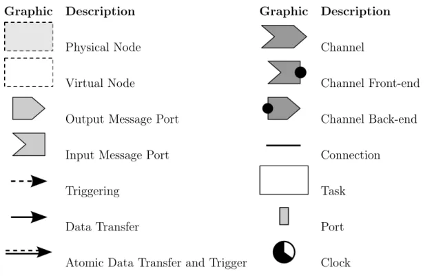
Graphic Description Graphic Description
Physical Node Channel
Virtual Node Channel Front-end
Output Message Port Channel Back-end Input Message Port Connection
Triggering Task
Data Transfer Port
Atomic Data Transfer and Trigger Clock Table 3.1: Graphical elements
Physical Nodes 21 Before we present the design description, we provide information about a graphical nota-tion of elements in Table 3.1. The graphical notanota-tion is similar to ProCom elements notanota-tion and there is a clear corresponding coupling between them. We have created the different no-tation to express that the diagrams are showing synthetized elements of the ProCom model.
3.1
Physical Nodes
When the system grows in number of connected components (e.g. car systems) we have to deal with its complexity and possible resource over-utilization. To avoid this problem some extra-functional properties of the components allocated to defined hardware are kept in the system model and compared with the hardware capabilities during the design time. Whenever reallocation of some components is required we would like to achieve a maximal reusability of the previously generated code.
The deployed system is decomposed to one or many physical nodes that can be con-nected. When we talk about a physical node, we mean a hardware device containing a CPU capable of task execution. Several properties such as hardware platform, operating system and communication ports have to be defined for each node. The middleware participates in the initialization of hardware components and establishing connections based on informa-tion gathered from the overall system model.
There is a complicated communication part of the initial connection check. But first we elaborate why the check is (or is not) necessary. Because system can consist of more than one physical node and it is needed to ensure that all nodes are fully functional before a message is sent. For example in the situation when one node sends message to another one, but the task located on the second node has not been activated yet. Hence it can not handle and react to incoming message.
This situation implies that the sender should check if the reader is ready or not, and only when the reader is ready the sender can activate its tasks. However, this can lead to a cyclic dependency between physical nodes. We can also see the fact that even if the connection is successfully established, the system may not be able to run correctly. From this point of view we have the system where every message (including the first one) has to be delivered and we should be also able to detect that. However our channel communication has only one-direction, hence we would need to extend its functionality. The current solution uses unreliable TCP connection, hence we decided to ignore the possibility of message loss and we assume that the node is ready when all its connections are established.
Furthermore, let us shortly discuss the possibility of accessing specific hardware parts (sensors, buttons, displays, etc.) required by tasks included in a virtual node. The first option is to create an universal drivers library, however it would be hard to cover differences in the hardware capabilities. Another way is to develop specific components with defined interfaces, which are usually tightly bound to the used hardware. Even if we consider using some abstract ProCom drivers or hard-coded functionality inside components there is still a tradeoff between reusability and effective utilization of resources.
Virtual Nodes 22
3.2
Virtual Nodes
As we mentioned in section 2.4, a virtual node is a set of ProSys subsystems. From a de-ployment point of view, we can look at virtual nodes architecture as an abstraction of target hardware devices which allows flexible allocation of the subsystems to different platforms. Information about these subsystems (periodic and event driven functionalities and appropri-ate data structures) is collected during the synthesis process and the virtual node definition is formed by combining the information. Therefore, the virtual node structure describes a set of functionalities (realized by tasks) and data structures.
The internal structure of task (shown in section 4.2.1) unifies the way how to store the in-formation about functionalities of different type. This virtual node implementation uses the advantage of simplified access to the information about tasks structured as an array. The start-up procedure easily calls initialization functions (init_routine) of each task and than it creates threads from methods periodic_task or sporadic_task depending on type of the task. Besides information about the tasks in the definition of the VN there are included lists of incoming and outgoing message ports.
However, we would like to mention that this structure was created for testing purposes and for further use it is necessary to consider the problems of multiple allocation of the same VN to one physical node. Consequently the support of multiple instances on the same physical node is missing for now and to use the same functionality of a virtual node multiple times it is necessary to create the copy of its code and change variables names.
3.3
Channels
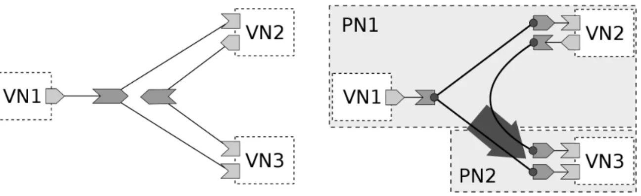
The objective of this section is to show steps of the designing system communication. We focus on top two layers — physical and virtual nodes. Let us remind that channels are used for virtual nodes composition. Virtual nodes are not connected to each other directly, but they are using channels instead. This section also discuss general issues of the message channels from the runtime point of view.
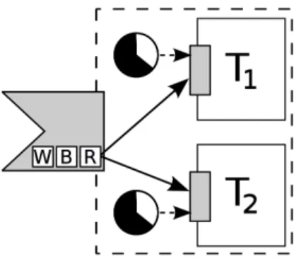
Example 1. To simplify the architecture example we will focus only on the physical layer and virtual nodes communication. Let us start with three virtual nodes (see Figure 3.1) communicating by passing messages through one message channel. More specifically the first VN sends messages to the other two. Now we have designed communication and the next step is to allocate VNs to physical nodes. For illustration, we deploy VN1, VN2 on PN1 and VN3 on PN2. A challenging phase of the realization is the right division of channel implementation to the right physical nodes and their connections. One possible approach, how this channel structure could be deployed, is presented in Figure 3.2 where the gray arrow illustrates direction of inter-node network communication.
In general, we create a channel front-end/back-end for each physical node if there is at least one writer/reader associated with the channel. Let N be a number of front-ends and
Channels 23
Figure 3.1: Single channel design Figure 3.2: Local and network connection
M be a number of back-ends of the same message channel. Then we need to define M ∗ N connections. In the previous example we have shown a simple one way communication where a shipped message was distributed to different nodes. However, consider the following scenario.
Example 2. Assume that we need to send replies back to the first physical node as it is shown in Figure 3.3. Therefore we add a new channel to the system model and connection between its back-end and front-end. We could straightforwardly define another connection, but if the type of physical connection provides two-way communication we take this advantage into account and use it for both channels (see the double-headed gray arrow grouping connections to the single network connection in Figure 3.4). An important motivation is the reduction of allocated resources on both physical nodes.
Channels 24
This solution was chosen because embedded systems typically have resource limitation in terms of maximum open connections. For example LwIP library uses a single task for each open connection. On the other hand, sharing a connection between multiple channels leads to the problem of message delivery to the right channel on the receiver side as we present in following example.
Example 3. Let us slightly arrange previous example as it is displayed in Figure 3.5. We keep the deployment layout same then we get the collocation of multiple channels to one physical connection (the gray arrow in Figure 3.6). The problem arises when the received message should be moved to the right channel on physical node PH2. Our solution consists of an additional channel identifier in the message structure. A small disadvantage is the larger size of transmitted data.
Chapter 4
The ProCom Middleware
The term runtime environment, as it is used in the context of this thesis, describes a set of services providing an API intended to allow running of the same component’s code allocated at virtual nodes (VN) on different platforms. To design and implement an API we have to look closer at the used operating systems (OS) features and communication semantics. In the following sections the platform abstraction layer and middleware API are described.
Because there are no dynamic changes allowed after the deployment process is finished, all the information about nodes and physical connections among them can be included directly in the generated code. This solution has many advantages in embedded systems, where it would be complicated to implement the reading of configuration files. Because of the fixed configuration storage there is no need for change mechanism implementation.
According to the requirements it would be beneficial to design the library architecture as two-layered to expandable parts. The top layer provides the API defined in section 4.2 that supports tasks creation, inter-component communication and virtual node creation. The underlying part, (described in section 4.1) provides an unified access to shared resources, operating system, and some common hardware.
4.1
Platform Abstraction Layer
To create an easily maintainable runtime library implementation it is necessary to define a certain level of platform abstraction. It helps not only with maintaining but also with porting the library to other hardware architectures or operating systems and in an ideal case without any changes in the top layer. The abstraction layer provides simplified access to system primitives such as threads, semaphores, mutexes and timers. Most of these primitives are same in the major part of used real-time operating systems. However, several problems have appeared.
The operating systems running under the middleware provide varying hardware abstrac-tion. We have focused only on hardware needed for communication such as Ethernet and serial ports. The hardware initialization is normally provided by the operating systems, but the function hardware_init is implemented to initialize the hardware of embedded systems,
Platform Abstraction Layer 26 where in some situations the initial values need to be written to the hardware registers. How-ever, this part is hard-coded in the middleware which is not the optimal solution. The func-tion connecfunc-tion_init is intended to initialize communicafunc-tion ports and library for network communication (e.g. Ethernet listener thread in the LwIP library, interrupt handlers and peripheral devices).
4.1.1
Threads
The basic purpose of the runtime environment is to enable independent execution of multiple components. In embedded or real-time systems threads are mostly called tasks. They are performing an activity in their own context.
Functions progress_thread_create and progress_thread_exit wrap system specific calls for creating and exiting system thread. These functions are available only on systems that support dynamic task creation.
4.1.2
Synchronization
Process synchronization support is needed to ensure that certain parts of code do not execute concurrently while they access to shared resource. If one thread attempts to get access to a resource that is already in use by another thread, the thread will be blocked until the resource is released.
However, blocking the thread is undesirable for many reasons mainly while high-priority task is running. Blocking in real-time systems brings more problems with their analysis and improper usage of locks or interactions between them can lead to undesirable state of system (deadlock, live-lock or priority inversion). In any case system has to provide at least one type of synchronization primitive.
We have implemented support for basic operations with semaphores (progress_sem_init, progress_sem_signaland progress_sem_wait) and also mutexes (progress_mutex_init, progress_mutex_lock and progress_mutex_unlock).
4.1.3
Sleeping
In some situations it is useful to resume task execution. A sleep system call places the running process into an inactive state for a defined period of time. The time parameter usually specifies only minimum amount of time that the process is inactive. The passive waiting is provided by progress_usleep function. More accurate timed sleeping that takes into account priority of the sleeping task (if it is supported by OS), is implemented in function wait_for_next_periodand introduced in section 4.2.1.
4.1.4
Memory Allocation
There is a problem with dynamic memory allocation, because of lacking or restricted support of functions like malloc in many RTOS. For example the dynamic allocation is not allowed
API proposal 27 after a scheduler is started in some systems. In case that dynamic allocation is unavoidable, it is possible to use a statically allocated memory pool.
4.2
API proposal
The API is supposed to help with producing reusable code for components by the developers as well as easily generated code for virtual and physical nodes. To achieve these goals we use the abstraction of the system primitives for synchronization (e.g. semaphores, mutexes), threads creation and sleeping for periodic actions. The set of auxiliary functions is also a part of the library to facilitate initialization of the hardware components and ProCom runtime environment in cooperation with underlying abstraction layer.
Before describing individual functions from the API, we provide an overall information about major functions. The middleware aims to provide easily usable data structures and functions for modeling, initialization and creation of elements at different ProCom modeling levels. Note that since the components are hierarchically composed, it is not necessary to use some of initialize functions explicitly, but they are called from the upper level initialization function automatically.
Let us provide a simplified list of the most important functions divided into categories according to model layers (full list can be found in appendix A.1):
1. Task (a) Get_message (b) Send_message (c) Write_data (d) Trigger_port 2. Virtual node (a) Init_task (b) Create_task 3. Physical node (a) Init_virtual_node (b) Create_virtual_node
In addition to the above functions we provide a wide range of extra macros (full list with description is provided in appendix A.2) for generating static data structures required for system modeling. These macros simplify the code generation templates and serve as inter-layer allowing small changes in library functions and structures without requiring a change in a previously created template.
API proposal 28
4.2.1
Task Creation
Model transformation for the system synthesis generates two types of tasks that differ in the way they are activated. The first type of task, called periodic, is formed by the combination of a clock element and the entry function of a connected ProSave component. We need to ensure further periodical activations at defined time, regardless of possible vary-ing execution time of the component entry function. The second task type is called sporadic and the name comes from the nature of the task to be executed in response to sporadically incoming messages to a connected message port.
Looking for solutions we focused on the question of providing easily maintainable code, that is open to slight modifications whenever new requirements on the middleware are dis-covered. The final implementation came from solution dealing with the problem of creating a common function for virtual node initialization, which is described later section.
The initial idea was to have one initialization function for each task type as it is described subsequently: create_periodic_task (create_sporadic_task) initializes the data struc-ture of a periodic (sporadic task) activated by timer (activated by incoming message) and is used as the entry function of corresponding thread.
However, during the implementation it became clear that it would be better to use only one function for creating tasks no matter of its type. The proposed solution has advantage in easier code generation, because all information are stored in a single data structure (shown in listing 4.1) and can be also referenced from virtual node to which they are allocated. Init_task executes initialization routine.
Create_task creates new thread from functions sporadic_task and periodic_task that include infinite loop with different internal implementation (described below).
Listing 4.1Task data structure
t y p e d e f s t r u c t _ _ p r o g r e s s _ t a s k { enum { T A S K _ P E R I O D I C , T A S K _ S P O R A D I C } type ; void (* i n i t _ r o u t i n e ) () ; void *(* s t a r t _ r o u t i n e ) (void *) ; void * arg ; u n i o n { c o n s t p r o g r e s s _ t i m e _ t p e r i o d ; p r o g r e s s _ s e m _ t * t r i g g e r ; } info ; int p r i o r i t y ; /* p r i v a t e : */ p r o g r e s s _ t h r e a d _ t t h r e a d _ h a n d l e r ; s t r u c t _ _ p r o g r e s s _ n o d e * v i r t u a l _ n o d e ; } p r o g r e s s _ t a s k _ t ;
API proposal 29 The process of creating tasks is split to two phases. In the first phase init_routine is called and internal task data are set up. This task memory initialization can usually be executed in any order, however there is problem with hardware initialization (in general with any shared resource) that does not have any abstraction layer handling multiple accesses.
During next phase the corresponding thread is initialized and then suspended until all tasks of all virtual nodes have been initialized and all physical nodes are ready to communi-cate. Detailed description of system startup problem is introduced in section 3.2.
Internal Implementation
The internal implementation of tasks uses the following functions to achieve desired behaviour while preserving platform independence. They are not directly part of the API, but they are closely connected to task definition.
Wait_for_other_tasks_init performs synchronization step. It waits for all the tasks of a vir-tual node to be initialized.
The next two functions are used in the periodic task loop. Their implementation is platform dependent with a view to gain benefits from operating systems that directly support periodic actions.
Compute_next_period enables to know when the task needs to be waken up based on time from previous task execution. It does not seem useful using FreeRTOS or RESCH1.
Wait_for_next_period waits until next period when the tasks can be executed again. It is called at the end of the working loop of the periodic task.
The last function is intended to wait for an external trigger at the beginning of the task loop. The activation can currently come only from an input message port that is associ-ated with the task. When the task is woken up, the incoming message must be read from the message port.
Wait_for_activation waits for a trigger to execute the routine of a sporadic tasks.
4.2.2
Virtual Node Creation
A virtual node is a set of ProSys subsystems, however for its successful initialization we need access to the tasks of each subsystem. Moreover, every virtual node will have a generated list of the message ports which have to be initialized before task activation.
Init_virtual_node initializes the tasks and message ports allocated to a virtual node. Create_virtual_node creates and initializes the data structure of a virtual node.
1A Loadable Real-Time Scheduler Suite for Linux (RESCH) is available on web page
Data structures 30 Before tasks can be activated, all virtual nodes (not only on same physical node) have to be ready.
Wait_for_other_nodes_init is a synchronization function that waits for the other VNs initialization before to launch the VN tasks.
4.2.3
Inter-node Communication
The only allowed way how a task can communicate with the other tasks located at a different virtual node is realized by message passing.
Send_message function packs data into a message and sends the message to an associated message channel. The action of packing and sending is atomic.
Get_message function reads data from an incoming message.
Because the semantic of message sending allows some special cases, we decided to split the functionality of message sending into two following independent functions. Together they do the same as send_message, but a message in the message port can be overwritten before it is triggered.
Write_data only packs data into a message and stores it in the associated message port. Trigger_port sends last stored data from the message port to the associated message
chan-nels.
If data are sent over network, it is necessary to convert them into the expected format for the communication protocol. Functions should be implemented for converting simple data types before they are sent. A typical examples of functions converting integers to and from the network format are htonl and ntohl.
4.3
Data structures
This section describes data types used on different levels of a system composition. We have experimented with dividing the information into two sets. The first one includes the informa-tion needed for establishing a connecinforma-tion and the other one contains the runtime informainforma-tion about the connection (e.g. socket identifier). This approach has shown to be really helpful, because it simplifies code generation and it also allows to hide the implementation of physical connections.
Based on the communication design introduced in previous sections following structures were implemented to achieve desired behaviors.
Data structures 31
4.3.1
Task Port
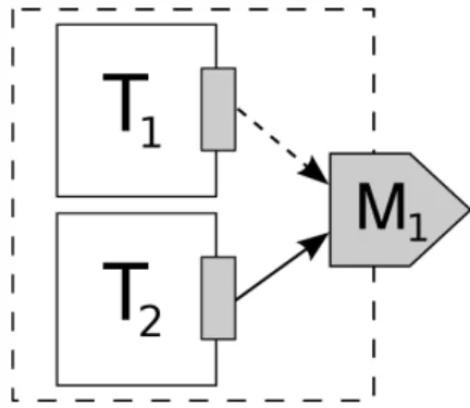
As the name suggests, this structure is used by tasks (services) to read data from an input message port or store data into associated output message ports. There are three supported ways how the task port can be connected to an output message port — only write data, only trigger port and atomic write and trigger. Similarly, the task can read the latest data from an input message port. The term – latest data – indicates content of message that has not been read by all associated sporadic tasks (triggered by event of the incoming message). In case that there are only periodic tasks reading from the message port they will read data from the newest received message.
Output task port is connected to possibly multiple message ports with attributes defining if the data connector between task port and message port is present and if the message port should be triggered when the data is written. We use the attributes rather than different methods in the API for the different types of message port associations. Input task port can be connected only to a single input message port. In addition to
the connector it includes only one other attribute that is true if the task is activated by the message port.
4.3.2
Message Port
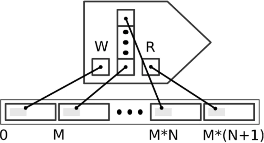
Message ports provide a mapping between message passing and trigger/data communication [2]. Taking into account various demands to reliability of message delivery we have decided to add buffers to the message port instead of channel. Moreover, it saves coping of data in case that the port is assigned to multiple channels. Another advantage of this solution is in simplifying the analysis of necessary buffer size to avoid message overwriting.
During the implementation work we faced a problem of minimizing data coping while using only statically allocated memory. Moreover, it is desirable to reduce the length of critical sections (buffers are possibly shared by multiple writers). After a closer examination
0
M
M*N
M*(N+1)
W
R
Data structures 32 of several possibilities (e.g. data stored in the task port, cyclic buffer for whole messages in the message port), it has been concluded that the message port should contain a cyclic buffer of the pointers to space for whole message and extra pointers to free memory for writing (W ) and reading (R) message. The extra space for writing message was chosen for keeping the message outside the buffer before the message port is triggered. Hence, the messages from the buffer can be sent by other task meantime. This also applies symmetrically for reading and sending messages from the message port.
During initialization phase all pointers are initialized as it is displayed in Figure 4.1.The main advantage is in the minimization of unnecessary data copying because we swap only pointers W and R with first unused and used item from buffer respectively. Let N be size of buffer and let M be size of the message. Then the memory of size (M + sizeof (void∗)) ∗ (N + 2) is used.
Input message port contains the defined space for at least one whole message. Whenever the message is received, the message data are written to the message port buffer. If all tasks triggered by the message port have read the message data from R, then the pointer to the oldest message data in the buffer is swapped with R pointer and the associated tasks are activated.
Output message port is an inverse to the input message port. When the trigger is acti-vated, the port stores a message with the data currently available on the input data port to its buffer and wakes up the sender task. Whenever the sender task is waken up, it sends messages from buffer belonging to the message port that woke him up to all associated channels.
Experiments have shown that the manual generation of structures of message ports with various options brings a lot of mistakes and, in addition, for minor modifications of the library it was needed to rewrite a large amount of already created code. To solve that problem we have defined a set of macros for the code generation which also makes possible to do some minor changes in the library without affecting existing code, and most importantly without changing the code-generating templates in the Pride tool. Equally important facts shall be revealed that this can solve most problems with generating different code for various platforms.
4.3.3
Channel
The channel is a kind of abstraction that stores information about connections used to send messages to the other virtual nodes possibly located on different physical nodes. It partici-pates in ensuring compliance of transmitted data.
A channel is logically composed of a set of front-ends and back-ends as was already de-scribed in Section 3.3. This approach brings several advantages. First, when a virtual node is deployed to different physical node only the information about connection between physical nodes is changed in channel front-end structure of the sender. Similarly, information about