59 Charles Burt
ABSTRACT
A major constraint for implementation of automated canal control is the complicated, tedious, and potentially error-ridden task of programming the control algorithm and associated overhead into PLCs (Programmable Logic Controllers). A typical control program may easily occupy 100 pages of Ladder logic that must be painstakingly developed and programmed. The most common argument in favor of Ladder logic – that local electricians can get into the
program and modify it if needed – is flawed because (1) local electricians do not understand the logic, and (2) Ladder cannot easily perform many mathematical tasks that are simple in other programming languages. In addition, the Ladder programmed on one brand of PLC is not directly programmable onto another brand because each brand has its own variation of the Ladder language.
ITRC’s approach to canal automation simulation includes building a model with an excellent hydraulic simulation program, characterizing each pool for storage and resonance, Matlab optimization of the control logic’s parameters based on hydraulic properties, and writing the logic in ISaGRAF. These services cannot be performed by integrators, who rarely, if ever, understand the theory behind
modern canal control. This has been misunderstood by districts when planning their long-term canal automation strategy, putting at stake large investments into the controller and software programming.
INTRODUCTION
When assisting districts in developing automated irrigation control systems, the Irrigation Training and Research Center (ITRC) of California Polytechnic State University (Cal Poly) has historically provided integrators with large detailed flow charts of logic. However, the ITRC’s approach has changed since learning about a new programming language used by PLC manufacturers – typically sold under the ISaGRAF® label. The interesting thing about ISaGRAF is that if a control program is written in this language in a sufficiently simple manner (which, though simple, is still extremely powerful), that program can be used in most of the major, industrial-strength Programmable Logic Controllers (PLCs).
1 Control Specialist, Irrigation Training and Research Center (ITRC), California
Polytechnic State University, San Luis Obispo, CA 93407 xpiao@calpoly.edu
There is no need to rewrite the program to match the PLC. ISaGRAF allows the programmer to use any combination of five IEC 1131-3 languages plus flow charts within the same, inter-linking shell. ITRC prefers to use the flow chart language for the backbone, with background details programmed in structured text. C and Ladder are other options.
ITRC has now worked on two large projects in which all of the integrator company’s skills in selecting/configuring hardware, radios, sensors, HMI, etc. were utilized, but the traditional integrator role of doing the actual algorithm programming into the PLCs was bypassed. Based on the success of these projects, ITRC has decided to follow this path on all future endeavors.
HYDRAULIC SIMULATION
Over the past few years, ITRC has continuously improved the canal automation procedures that include developing and optimizing the control logics inside an unsteady, open-channel hydraulic simulation model and implementing those control logics in the field.
The first step is to decide upon the control strategy to use. Once that is done, one must build the canal model inside the simulation program, which has been
tailored by ITRC over the past 10 years to examine the control of gates and pumps in canals. It simulates actual flows, velocities, and water depths throughout a complete system and can provide specific information for any position within a pool in time increments as small as one second. ITRC normally starts a simulation by building the canal model based on district-provided canal physical dimensions, roughness, and other information, or actual data surveyed by ITRC using GPS and/or Total Station instruments.
The simulation program provides the following capabilities:
a. Customize the control file based on the actual control scheme and availability of the sensors;
b. Export the data that can be used to plot out the actual workings of automatic controllers on each check structure in response to simulated changes in flow at turnouts and at the entrance to the canal for visualizing the canal system response.
Basically, the effects of any control logic with the chosen parameters for any specific multi-pool canal system can be simulated.
Optimizing the Control Algorithm’s Associated Parameters
The general control algorithm by ITRC for upstream or downstream control (there are many variations of these) usually utilizes either Proportional or Proportional-Integral or Proportional-Proportional-Integral-Differential. Most algorithms selected by
integrators are some variation of a “littleman” control. Almost all of the
parameters of these algorithms are chosen empirically by integrators either in the field or while programming regardless of the high/low flow conditions or the pool and gate dimensions. This is a shortcoming since there is no control effect
verification of these logics and their associated chosen parameters.
It is known that in most cases, the wave travels along the pool; when it hits a check structure, it is reflected back and travels up to the next check structure on the upstream side. The wave travels back and forth forming resonance, which can be amplified along the canals and results in gate/pool instability at the 1st
downstream control check structure and at the last upstream control check structure. This phenomenon is most common in flat canals using downstream control, and can cause serious control problems with canal control systems that did not use simulation, and where the control logic and associated parameters were empirically chosen.
With hydraulic simulation, ITRC is able to simulate how the wave travels along the pools as well as simulate the best performance of each gate and the associated controlled pools under different control logics and optimized parameters. ITRC found that the PIF (Proportional-Integral-Filter) control logics, which are obtained by adding a Filter to the Proportional-Integral-Differential control logics with optimized parameters, can greatly eliminate waves and improve upstream and downstream control. The optimized parameters are specifically obtained from the Matlab routines that were developed by P.J. Van Overloop and J. Schuurmans of the Netherlands. These Matlab routines have been continuously updated over the past five years, and are based on the hydraulic characteristics of surface area, resonance peak and delay time of the pools to optimize the control logic
parameters. Currently, these Matlab routines are getting to a start-of-art point that can directly optimize a set of parameters without the need to finely tune them.
LIMITATIONS OF LADDER LOGIC OR OTHER PLC LANGUAGES After the control logic and the optimized parameters are chosen with the
simulation, ITRC would previously draw the control logic in a non-executable flow chart. Then the integrator would program the control logic according to the ITRC-provided flow chart in the language environment of Ladder logic or another modular language that is proprietarily supported and supplied by the PLC
manufacturer.
Different PLC manufacturers may provide totally different software programming environments though they provide the common digital/analog inputs/outputs. The most common are:
• A Ladder logic programming environment provided by the manufacturer; • A modular programming environment provided by the manufacturer, with the
• The manufacturer’s own software combined with a 3rd party software such as
ISaGRAF as a software programming tool. In this case, users have the option of choosing which language to use when programming the control logics. It is worthwhile to mention that some PLCs are only suitable for monitoring and performing simple control actions such as turning pumps on and off or raising and lowering gates with extremely simple logic. Additionally, some PLCs are unable to receive or transmit ASCII commands/characteristics through a COMM port, which means they do not have the potential to take readings from some electronic flow meters. Some simple modular PLC software cannot be programmed for multiple gates and the combination of both the gate and pump controls, because they lack a clear execution sequence between the modules that perform the arithmetic and logic functions. In this case, even if the PLCs already exist at a site, the user must use another PLC of the same type but of a higher quality, or switch to another type of PLC – if better control is needed. Because the cost of a PLC is only a very small part of the total cost of hardware, programming, and implementation, there should be absolutely no hesitation about purchasing excellent PLCs.
Most industrial PLCs use the Ladder language. But we have found that (i) the Ladder language used in a Modicon controller is different from that used in a SCADA-Pak, for example, and (ii) integrators often prefer a specific PLC brand because they have already programmed their “proprietary” code to do certain functions, such as calibration of instruments. When programming some PLCs, the ITRC-provided flow charts needed to be created from scratch each time by each integrator for each PLC. This limits development possibilities, since every programming inevitably includes error, which takes time and effort to correct. On one project, ITRC found that programming a control logic by a well-known integrator took seven tries and more than one year to review and correct after the integrator first programmed the ITRC-provided control code in Ladder logic. To avoid such hassle and frustration, ITRC has decided to switch to ISaGRAF software, which allows the programmer to easily transfer a control code that has been tested in the field to other, different PLCs that also accept ISaGRAF.
ISaGRAF: INTRODUCTION AND EXPLANATION
ISaGRAF is a product of ICS Triplex. The ISaGRAF program is consistent with the standards of IEC 61131-3 industrial control languages, and is sold to PLC manufacturers. ISaGRAF was originally introduced in 1990 for bridging the gap between microcomputer systems and PLCs; currently, it is suitable for both centralized and distributed control systems that support 32, 64, 128, 256, or unlimited input/output points.
a. Version 3.32 (latest version 3.54): Most PLCs support this version, a 16-bit application. One ISaGRAF 3.## control code is run within one PLC. b. Version 4.5 Work Pro: Newest version with some new features such as
language editing enhancement and XML (eXtended Markup Language) that provides the basis for the well-known HTML (Hyper Text Markup Language). It is a 32-bit application; one ISaGRAF 4.5 Work Pro can control many PLCs, and is capable of centralized control.
With ISaGRAF, the controller gains features such as data quality, millisecond time stamping, and sequence of events, etc.
PLC manufacturers rarely buy ISaGRAF Version 2.4 Enhanced anymore, though it is still available. This version was provided earlier and many of its features have been incorporated into the 4.5 version by ICS Triplex.
The relationship between ISaGRAF and the PLC is shown in Figure 1.
Figure 1. Relationship between ISaGRAF and the PLC.
The driver and runtime module are normally obtained from the PLC manufacturer at an insignificant or no cost. The ISaGRAF license fee may also vary depending on how many PLCs need to be run. Some PLCs need to be upgraded with an ISaGRAF chip.
ISaGRAF is independent of hardware and software during the control code
development. In order to program and simulate the control code inside ISaGRAF, the user needs to have a WorkBench module, which can be purchased from either ISaGRAF (ICS Triplex) or from the PLC manufacturer. The simulation tool inside ISaGRAF enables the programmer to examine how the code is running and what the value/state for each variable is when the actual PLC is not connected. This is a powerful tool since it provides the capability to run and debug the control code before the PLC controller is chosen. The debug tool inside
ISaGRAF requires the PLC to be connected, in which case the user needs to have the ISaGRAF Runtime module that normally can be provided by the PLC
manufacturer. ISaGRAF Programmable Logic Controller Communication Driver, Runtime module (Establishes the links between ISaGRAF and PLC hardware)
ISaGRAF IEC1131 Compliance
IEC 61131-3 is the basis on which the organization PLCopen operates
(http://www.PLCopen.org). This standardized programming interface allows people with different backgrounds and skills to create different elements of a program during different stages of the software lifecycle: specification, design, implementation, testing, installation and maintenance. Via decomposition into logical elements, modularization and modern software technique, a program that meets IEC 61131-3 standards is structured with the goal of increasing its re-usability, reducing errors and increasing programming and user efficiency. Since the release of the IEC 61131-3 programming standard, users are able to exchange their programs, libraries and projects between development environments.
There are other software packages such as MULTIPROG® (KW Software, www.kw-software.com) and 4Control (Softing, (www.softing.com), which also meet the criteria established by IEC 61131-3. ISaGRAF commands 60% of the market because of its nice interface and wide compliance with various brands of PLCs. Users such as integrators purchase an ISaGRAF program that may contain the PLC-specific modules (depending on the PLC) or the ISaGRAF license from the PLC manufacturer.
The ISaGRAF Application Development Workbench supports all of the standard IEC 6-1131 control program languages plus Flow Chart. These six languages are:
1. Sequential Function Chart (SFC) 2. Function Block Diagram (FBD) 3. Ladder Diagram (LD)
4. Structured Text (ST) 5. Instruction List (IL) 6. Flow Chart (FC)
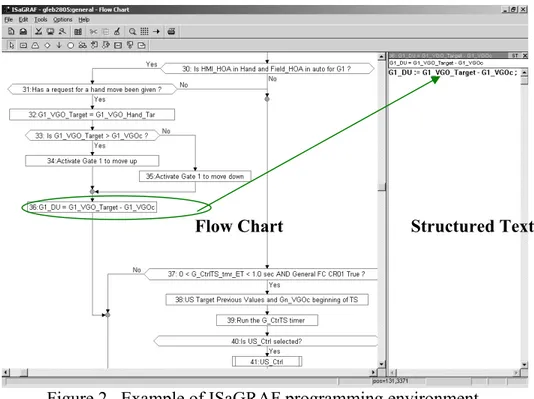
Any or all of the control languages may be needed in an application. Typically, a Flow Chart in Structured Text can do almost all of the programming; this is the style used by ITRC for all control logic programming in ISaGRAF. Figure 2 is an example of the ISaGRAF programming, in which a Flow Chart (left window), along with Structured Text (right window) is used. The execution sequence follows the arrow that is drawn out in the left side of the flow chart.
Figure 2. Example of ISaGRAF programming environment. Customized Libraries
PLC companies such as Allen-Bradley, ABB, Divelbiss, ICS, NEC, Omron, Philips, Sixnet, Control Microsystems, and many more have taken this "basic" programming environment and have developed customized libraries or extensions with functions that duplicate common and often unique capabilities that reside within their controllers. In general, ITRC does not use those customized libraries, because it limits our ability to use a “universal” version of ISaGRAF. We have not found a need to use any of the special routines; the standard ISaGRAF provides sufficient flexibility and ease of use.
Some special functions such as feed and forward variables between controllers may require using some special functions from the PLC manufacturer’s
customized library, but this can be easily added as separate modules or language functions inside ISaGRAF. Since this is normally just a small amount of
programming work, it does not constitute a shortcoming for ISaGRAF. Engineers and ISaGRAF
Some might say that it is much more difficult to learn the ISaGRAF languages than it is to learn standard Ladder language, and there may be some discussion regarding the merits of an integrator or electrician’s ability to understand Ladder versus ISaGRAF. For a programmer who has used Ladder logic for a long time, it might be true that he is very used to determining which function block is being executed by looking for the energized shunts inside the Ladder language.
However, for the same arithmetic and/or logic function, there is no doubt that the Structured Text language is more understandable than the Ladder logic block function for a first-time learner, and ISaGRAF takes less time and less effort to grasp than Ladder logic.
For an organization such as ITRC, the problem comes in the field where the electricians understand Ladder logic but don’t have a clue about the control logic, flow charts, or other languages. If they do make changes to the Ladder, the electricians more often “correct” something that is already right, or do not make any improvement to the thing that is wrong. It is very typical for an electrician to never “touch” the control code that is programmed by the integrator in Ladder language, even when the electrician understands the Ladder. Therefore, it is not necessary to program the control code in Ladder for the electricians’ sake. Moreover, if the electrician were able to familiarize himself with ISaGRAF, it would be easier for him to make changes if needed.
If the programmer sticks with the standards of the IEC 1131 programming language, then he/she will be able to compile and run the control code in most applicable PLCs. Another merit of ISaGRAF is that all variables (tags) can be used as in C or Fortran without assigning the registers while doing the
programming or debugging. After everything has been compiled and is running correctly, only those tags that will be input through or displayed in the Human Machine Interface (HMI) software need to be assigned with registers. This makes the programming procedures less painful and avoids the confusion of registers being repeated for different purposes.
DISTRIBUTION OF IMPLEMENTATION TASKS BETWEEN ITRC AND INTEGRATORS
Currently, ITRC is responsible for providing:
• ISaGRAF control code for the proposed control logic, to minimize the hassles
of leaving the programming to the integrators and reviewing their work to correct errors;
• correct control actions in both manual and auto movement mode and the
correct alarm generation when needed. The integrator is responsible for:
• sensor selection and installation; • PLC wiring and labeling;
• radio and repeater; • alarm auto-dialing; • HMI design.
The line that distinguishes the ITRC-provided ISaGRAF control code and the integrator’s work is the assigned registers for each site. ITRC provides to the
integrator a full explanation of the tags and the assigned registers and their associated recommended values that need to be designed and displayed in HMI. The integrator ensures that the ITRC-listed HMI variables that are assigned with the associated registers can be either input through or displayed in HMI either through radio or other communications mode.
The key in such a co-operation is a clear line between tasks and responsibilities. Using this approach, ITRC has completed control logic programming in
ISaGRAF and it has passed the bench-testing for upstream water level,
downstream water level, flow control and some special spill control situations for on-site parallel check structures. One customer has already finished transferring the previously programmed Ladder logic to ISaGRAF for the upper part of the canal’s upstream level control, and finished the programming in ISaGRAF for lower part of the canal’s automation with some additions of customized changes such as downstream level control and flow control for gates and pumps, both with and without Variable Frequency Drives (VFDs). ISaGRAF has facilitated the transfer of the control code between controllers, and the development of the control code for a new system takes much less time. This, combined with the revised roles of ITRC and the integrator, makes the field implementation of the control code much quicker and more efficient.
REFERENCES http://www.PLCOpen.org
http://www.isagraf.com
Burt C.M and X.Piao. 2002. Advances in PLC-Based Canal Automation, Proceedings of USCID/EWRI Conference held in San Luis Obispo, CA. pp 409-421.