MATERIAL FLOWS IN THE
WATERJET INDUSTRY
An environmental perspective
Master of Science Thesis
Environmental Technology and Management
Linköping University
Author: Daniele Abbatelli Supervisor: Joakim Krook Examiner: Niclas SvenssonMATERIAL FLOWS IN THE WATERJET INDUSTRY
AN ENVIRONMENTAL PERSPECTIVE
Master of Science Thesis
ISNR: LIU-IEI-TEK-A--14/01963—SE
Author: Daniele Abbatelli Supervisor: Joakim Krook Examiner: Niclas SvenssonEnvironmental Technology and Management
Linköping University
June 2014
A
CKNOWLEDGEMENTS
The inspiration for this work has been provided by Anders Jönsson, from the Swedish Waterjet Lab, who also provided knowledge and contacts in the world of waterjets without which this study would not have been possible.
Special thanks also go to Donald Bengtsson, from Tebeco, and Kjell Lauritzen, from GMA Garnet, for the useful discussions and the precious information on the abrasive market.
I would also like to thank my supervisor, Joakim Krook, and my examiner, Niclas Svensson, for their guidance and their suggestions throughout the whole work.
Finally, I would like to thank all the Växjö people, without whom I wouldn’t be here now, and all the friends I met in these two years in Linköping, who all contributed to make this period unforgettable one semester after the other.
Last but not least, I would like to thank Mariana, for standing me when I am in bad mood like just few other people can do.
A
BSTRACT
Abrasive Waterjet cutting (AWJ) presents many advantages over competing machining techniques, but several issues are related to the high volume of materials (and in particular of abrasive) used in the process. In this study, the environmental impact of the material flows in the abrasive waterjet industry has been analyzed adopting a life cycle perspective in order to individuate which phases place the largest burden on the environment. Moreover, three alternative abrasives (crushed rock, recycled glass and synthetic abrasive) and three disposal practices (in-site recycling, off-site recycling and recycling as construction material) have been also evaluated to estimate the benefits that can be achieved if these could be used in place of garnet abrasives and landfilling. The transportation of the abrasive resulted to be the phase that has the largest influence in every case and thus should be reduced as much as possible. For what concerns the alternative options, the usage of recycled glass and the in-site recycling of the abrasive were the two alternatives with the best environmental performances. However, crushed rock could be the best option for what concerns the global warming potential if carbon sequestration due to carbonation of silicate rocks is taken into account. Off-site recycling and recycling as construction material are good options only if the transportation to the recycling site can be reduced. Synthetic abrasive are instead found to have a much larger impact compared to every other alternative examined.
T
ABLE OF
C
ONTENTS
Acknowledgements ... III Abstract ... IV Table of Figures ... VII Table of Tables ... VII Table of Charts ... VIII List of abbreviations ... IX
1 Introduction ... 1
1.1 Background ... 1
1.2 Aim ... 3
2 Material flows in AWJ industry... 4
2.1 Origin and applications of AWJ ... 4
2.2 Description of an AWJ machine ... 5
2.3 Abrasive characteristics ... 7
2.4 Abrasive market and garnet production ... 8
2.4.1 Alternative abrasives ... 10
2.5 Management of the waste flows ... 11
2.5.1 Alternative recycling and disposal practices ... 12
3 Theoretical framework ... 15
3.1 Industrial ecology ... 15
3.2 Environmental system analysis ... 15
3.3 Life Cycle Assessment... 16
4 Research design and methods ... 17
4.1 Scope definition ... 18
4.1.1 Scenarios development ... 19
4.2 Inventory analysis ... 21
4.2.1 Reference scenario: Alluvial abrasive and landfilling ... 22
4.2.2 Production scenario 1: Crushed rock abrasive ... 24
4.2.3 Production scenario 2: Recycled glass abrasive ... 25
4.2.4 Production scenario 3: Synthetic high-performances abrasive ... 26
4.2.5 Disposal scenario 1: In-site recycling ... 26
4.2.6 Disposal scenario 2: Off-site recycling ... 28 V
4.2.7 Disposal scenario 3: Recycling as construction material ... 29
4.3 Impact assessment ... 30
4.4 Interpretation ... 30
5 Results ... 32
5.1 Analysis of the scenarios ... 32
5.1.1 Reference scenario: Alluvial abrasive and landfilling ... 33
5.1.2 Production scenario 1: Crushed rock abrasive ... 37
5.1.3 Production scenario 2: Recycled glass abrasive ... 40
5.1.4 Production scenario 3: Synthetic high-performances abrasive ... 41
5.1.5 Disposal scenario 1: In-site recycling ... 43
5.1.6 Disposal scenario 2: Off-site recycling ... 44
5.1.7 Disposal scenario 3: Recycling as construction material ... 47
5.2 Comparison of the scenarios ... 49
5.3 Validity of the results ... 51
6 Conclusions ... 58
6.1 Implications for the AWJ industry ... 58
References ... 60
Appendix I: Processes modelled in SimaPro ... 65
Service processes ... 65
Production alternatives ... 67
Use phase ... 69
Disposal alternatives... 69
Complete scenarios ... 72
Appendix II: Illustration of the scenarios ... 74
Reference scenario ... 74
Crushed rock scenario ... 75
Recycled glass scenario ... 76
High-performance abrasive scenario... 77
In-site recycling scenario ... 78
Off-site recycling scenario ... 79
Recycling as construction material scenario ... 80
Appendix III: LCIA Results ... 81
T
ABLE OF
F
IGURES
Figure 1: Schematic of an AWJ system. Source: Pi, 2008 ... 6
Figure 2: Schematic of the material flows through a waterjet cutting machine. ... 17
Figure 3: Life cycle of an abrasive material. ... 18
Figure 4: Schematic of the alternative materials flows in waterjet industry. ... 20
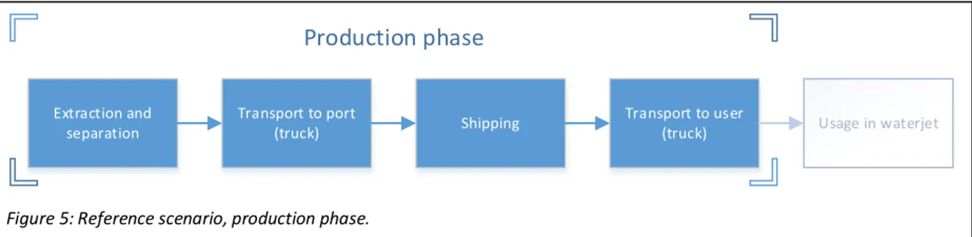
Figure 5: Reference scenario, production phase. ... 22
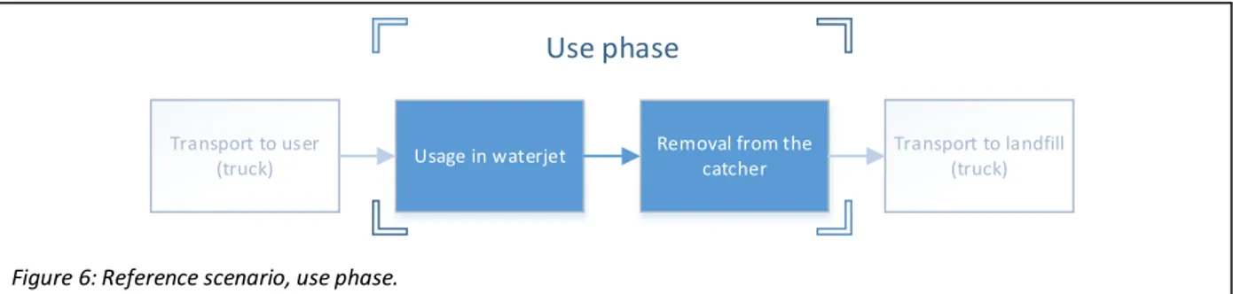
Figure 6: Reference scenario, use phase. ... 23
Figure 7: Reference scenario, disposal phase. ... 24
Figure 8: Crushed rock scenario, production phase. ... 24
Figure 9: Recycled glass scenario, production phase. ... 25
Figure 10: Synthetic abrasive scenario, production phase. ... 26
Figure 11: In-site recycling scenario, disposal phase... 27
Figure 12: Material and energy flows within an abrasive recycling unit ... 28
Figure 13: Off-site recycling scenario, disposal phase. ... 28
Figure 14: Recycling as construction material, disposal phase. ... 29
T
ABLE OF
T
ABLES
Table 1: Garnet production in tons, per country. Based on data of Olson (2014, 2002). ... 9Table 2: Abrasive use, each abrasive used at least some of the time. Based on data by Mort (1995). ... 10
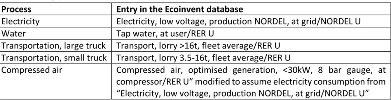
Table 3: Modelling of the basic processes. ... 21
T
ABLE OF
C
HARTS
Chart 1: Overview of the reference scenario ... 33
Chart 2: Reference scenario, production phase ... 34
Chart 3: Reference scenario, use phase. ... 35
Chart 4: Usage of the abrasive, contribution of different factors. ... 35
Chart 5: Reference scenario, disposal phase. ... 36
Chart 6: Crushed rock scenario, different modelling options for the abrasive extraction and milling. ... 37
Chart 7: Crushed rock scenario, production phase. ... 38
Chart 8: Crushed rock scenario, overview ... 39
Chart 9: Crushed rock scenario with carbonation, overview ... 39
Chart 10: Recycled glass scenario, production phase. ... 40
Chart 11: Recycled glass scenario, overview. ... 41
Chart 12: Comparison of the production phase of high-performances abrasives ... 41
Chart 13: High-performance abrasive scenario, production phase. ... 42
Chart 14: High-performance abrasive scenario, overview. ... 42
Chart 15: In-site recycling scenario, disposal phase. ... 43
Chart 16: In-site recycling scenario, overview. ... 44
Chart 17: Off-site recycling scenario, disposal phase. ... 45
Chart 18: Off-site recycling scenario, overview. ... 45
Chart 19: Comparison of different recovery rates for off-site recycling. ... 46
Chart 20: Comparison of different construction materials... 47
Chart 21: Recycling as construction sand, disposal phase. ... 47
Chart 22: Recycling as limestone for construction, disposal phase. ... 48
Chart 23: Recycling as construction sand, short transportation. ... 48
Chart 24: Comparison of the production phase of different abrasives. ... 49
Chart 25: Comparison of different disposal options. ... 50
Chart 26: Comparison of the different scenarios over the whole life cycle. ... 51
Chart 27: Comparison of the different modelling options for the production of 1 kWh of electricity. ... 52
Chart 28: Overview of the reference scenario if electricity is modelled as Swedish mix. ... 53
Chart 29: Comparison of different scenarios assuming electricity as Swedish mix. ... 53
Chart 30: Comparison of the different modelling options for the transportation of 1 ton over 1 km. ... 54
Chart 31: Comparison of the different scenarios assuming a large truck for all transports... 55
Chart 32: Comparison of the different scenarios assuming 18000 km of naval transportation. ... 56
Chart 33: Overview of the reference scenario assuming 18000 km of naval transportation. ... 57
L
IST OF ABBREVIATIONS
AWJ Abrasive Water Jet
PWJ Pure Water Jet
LCA Life Cycle Assessment
LCI Life Cycle Inventory
GWP100 Global Warming Potential at 100 years
ODP Ozone Depletion Potential
CNC Computer Numerical Control
EDM Electro Discharge Machining
EPD Environmental Product Declaration
1 I
NTRODUCTION
The word “waterjet” is used to indicate a stream of water forced out through a small aperture and its meaning extends to all the equipment and processes that pertain to, or are operated by a waterjet (Random House, 1999). It is therefore a generic term whose meaning spans a wide range of different uses and technologies: waterjets are employed for many different purposes, ranging from the simple cleaning to high-pressure machines that are able to cut through almost every material.
In this paper, unless otherwise stated, the term will be used to indicate those applications of waterjets that are employed in the industry for machining of various kinds of parts. These kind of operations are usually carried out indoor, with the jet forming equipment mounted on a CNC table, allowing to effectively cut intricate shapes in a wide range of materials also thanks to the addition of an abrasive medium to the water flow.
1.1 B
ACKGROUNDWaterjet machining is a non-conventional manufacturing process that involves the use of a jet of water to cut through a material. In this process, a large amount of energy is concentrated into a small quantity of water in the form of pressure. The pressurized water is then forced through a small orifice, producing a narrow stream of water that travels at high speed and is able to produce a cut into a soft material such as paper or rubber. In order to increase the cutting power of the jet, small solid particles are often added to the pure water, allowing the jet to also cut through harder materials such as metals or ceramics. Hence, from a materials point of view, two different variations of the waterjet machining technology can be distinguished: one uses water alone to produce the cut and is therefore called Pure Water Jet (PWJ) while the other also makes use of the erosive power of an abrasive material and is thus called Abrasive Water Jet (AWJ).
While PWJ presents several advantages over competing techniques for a number of specific applications, the flexibility of AWJ when cutting a wide range of materials proved to be a key asset for the increasing diffusion that this technology has experienced in recent years: indeed, AWJ can cut through almost every material, including those that are too hard, to brittle or too soft to be effectively cut with other technologies (Khan and Yeakub, 2011).
From an environmental perspective, an AWJ does not produce any dust, fume or airborne particle and operates without chemicals. The waste material produced is mainly composed by water and spent abrasive with traces of the machined material. Since garnet or other inert minerals are generally used as abrasive, the solid waste is usually suitable for landfilling, while wastewater is simply drained to the sewer, even if water treatments may be necessary in some cases (Arleo, 2010).
On the other hand, the technology also presents some drawbacks: even if the waste is most frequently of easy disposal, the volume of effluents produced by this technique is substantially higher than any other competing technique, and the costs for material supply and disposal can be important. In particular, the cost for abrasive can represent a large share of the total operating cost (Babu and Chetty, 2003; Hoogstrate et al., 2006). In addition, if hazardous material (such as lead) is processed, an appropriate treatment of the waste flow is required. Recycling of water and abrasive is possible, but not common practice (Holmqvist and Honsberg, 2007). Finally, the abrasive material is usually extracted in few sites in
Australia, India or United States and thus transportation is a factor that must be taken into consideration, especially if the abrasive is utilized in locations that are far away from the extraction sites.
Since abrasive plays a major role in the total operating cost, several scientific contributions aiming at reducing the cutting cost also consider different ways to reduce the expenses for abrasive: a certain number of investigations has been carried out to evaluate alternative abrasives materials (see as example Fang et al., 1998; Foldyna et al., 2000; Martinec et al., 2002; Vie, 1983), including those that may potentially be produced with recycled material (as example crushed glass, as mentioned by Gent et al., 2012) or as byproduct of other industries (as example copper slag, as in Vie, 1983). However, these alternative abrasives failed to penetrate in the market, and 90% of the AWJ shops uses garnet as abrasive material (Mort, 1995). Pi (2008) developed a framework evaluating in detail the possibility of improving the profit rate of AWJ shops through an optimization of the process parameters and also assessed the recycling of the abrasive as a way of reducing operating cost, while other contributions aimed at assessing the technical feasibility of abrasive recycling and recharging (Babu and Chetty, 2003, 2002; Pi et al., 2012, 2009). Only reduced scientific literature has been found analyzing the possibility of recycling the spent waterjet abrasive in other non-waterjet processes, such as concrete or asphalt production (Mathews, 1998) but similar studies have been carried out for sandblasting abrasive, that presents similar characteristics (Heath and Nelson, 1998; Sua-iam and Makul, 2013; Webster and Loehr, 1996). Other research efforts are instead aimed at eliminating the need of dedicated abrasive material, as example replacing it with ice; while ice can be an effective replacement for garnet for some uses, it cannot effectively replace it when it comes to cut harder materials; moreover, the technology is still at a prototypal stage (Life+ project ICEJET, 2013).
Very little literature specifically dealing with waterjet cutting from a sustainability perspective was found: Aurich et al. (2013) uses general literature dealing with performance and surface quality to extract knowledge about the sustainability of a series of abrasive processes, including waterjet cutting. Duflou et al. (2012) reports a general lack of data in the life cycle inventory (LCI) databases regarding the environmental impact of manufacturing processes, especially in case of unconventional ones like waterjet machining.
A simplified life cycle inventory of the technology is performed by Ny et al. (2009) within a paper that focuses on the application of system analysis tools to support strategic decisions. The authors analyze the global warming potential of the production phase of a waterjet machine and compare it to 1500 operation hours of the same machine. It is noted how most of the sustainability problems of the technology are tied to its material consumption in the use phase: indeed, the relatively large amount of water and sand used in the process (which represents in itself a sustainability issue) also implies the consumption of significant fossil energy supplies for their transportation and creates a large amount of waste sediments that can cause land occupation and emit hazardous cutting remainders. The same authors also identify the abrasive sand as the main material that needs to be in focus for future efficiency measures, since its impact (on the GWP100) is much larger than the one of water, mostly due to its transportation from the extraction site (considered in Australia). Among its final recommendations, Ny et al., (2009) suggest to replace virgin sand with locally produced abrasive and introduce a system that allows recycling of the materials, but no options are evaluated and future sustainability analysis of the available alternatives is advised. Moreover, the life cycle inventory in itself is only intended to be a case study to demonstrate the applicability of this tool to the framework defined by the authors, and therefore is highly simplified. As of today, no other study was found in the literature evaluating from a sustainability perspective the
performances of different waterjet abrasives nor those of different management practices for the spent materials.
At the present time, the lack of focus on the environmental sustainability of the waterjet process and in particular on the management of the water and abrasive material used does not appear to have a negative impact on the diffusion of this technology, since the solutions currently adopted (garnet sand as abrasive material and landfilling of the produced waste) seem to offer an acceptable tradeoff between cost, performances and environmental impact. On the other hand, it can be foreseen that other options offering better environmental performances may become desirable in the future under the pressure of stricter environmental regulations and increased costs related to resource depletion.
This is particularly true for AWJ activities carried out in Scandinavia: due to the distance from the main garnet production sites, importing abrasive presents significant difficulties, while the regulations on landfilling of solid waste are among the strictest in the world and, if further tightened up, may imply the impossibility of disposing of solid waste from waterjet machining in an economical way. There is therefore a demand, from the industry organization, for a detailed analysis of the material flows in the waterjet machining industry.
1.2 A
IMThe preset study has been commissioned by the Swedish Waterjet Lab in cooperation with the Scandinavian Waterjet Association with the purpose of carrying out a detailed analysis of the material flows in the AWJ machining industry in relation to their environmental impact.
The aim of the study is therefore to perform an environmental evaluation of different material flows and waste disposal practices for the AWJ industry, identifying which activities cause the largest burden on the environment and examining how different alternatives may improve the current situation.
These information may thus be used by organizations operating at all levels in the AWJ industry for purposes such as decision support or strategic planning, providing a guidance to improve the environmental performances of the waterjet technology while maintaining its economical sustainability. This report is consequently intended for a target audience of entities operating at all levels in the waterjets industry. Examples of such organizations are:
• Producers and distributors of abrasive material
• Producers, assemblers and distributors of AWJ equipment • AWJ users of every type and size
• Waste haulers • Trade associations • Research entities
Since this study stems from necessities that are specific of the Scandinavian AWJ industry, the results are to be considered fully representative for the Scandinavian AWJ industry only, and special care should be used if these are to be utilized in other settings. Finally, even though a certain number of comparisons between materials and management practices has been carried out, these are not intended to be representative of any specific commercial product and the results should only be presented as integral part of the present paper to subjects within the waterjet industry.
2 M
ATERIAL FLOWS IN
AWJ
INDUSTRY
In order to evaluate the different material management practices in use, the AWJ industry must be described first, identifying and quantifying the substances in use, illustrating their origin and characteristics and thus defining the predominant material flows and the operations required for their support.
This chapter will carry out this task in the following way:
• Section 2.1 will describe the origin of the AWJ technology, clarifying its relation with PJWs and describing its potential applications also beyond the machining of parts.
• Section 2.2 depicts the internal functioning of an AWJ machine in order to catalogue and quantify the different materials involved in its use phase, providing an idea of the influence that the different substances have in the process.
• Section 2.3 describes the characteristics of the abrasive material.
• Section 2.4 illustrates the market and the production of almandine garnet, the most common abrasive for waterjet cutting, and introduces some possible alternatives.
• Section 2.5 finally describes the handling of waste and all the other processes happening after the machining of a part.
2.1 O
RIGIN AND APPLICATIONS OFAWJ
The waterjet technology originally developed in the mining sector and dates back to ancient times, with documents illustrating the usage of water to facilitate the mining of valuable material in Egypt and later in Roman times. More recently, pressurized water was used in California to excavate gold during the 1853-1886 period and later on the technique was applied to coal mining in the Soviet Union during the 1930s (Summers, 2003).
A first application of water as industrial cutting device was developed in 1933 by the Paper Patents Company, in Wisconsin, which patented a machine using a waterjet to cut a sheet of paper (Fourness and Pearson, 1935). From that starting point, the water pressure (and thus the cutting capability) of waterjets continuously increased: in the 1950s, short burst of very high pressure able to cut wood were obtained (Flow International Corporation, 2014), but no commercial application of the technology was developed. This had to wait until the 1970s, when the first equipment was installed and waterjets became for the first time a viable option for the manufacturing industry (Summers, 2003).
Despite the high pressure used, the cutting capability of the pure water jet (PWJ) was still limited to a small range of softer materials. A breakthrough in this sense arrived in 1979, when Dr. Mohamed Hashish developed a nozzle which was able to combine an abrasive material (such as garnet) into the high-pressure water jet, drastically increasing its cutting power and allowing it to cut materials such as glass, steel and concrete. By 1983, the first commercial abrasive waterjet (AWJ) cutting system were sold (Flow International Corporation, 2014). Since then, the technology further developed, allowing Abrasive Waterjets (AWJ) to efficiently machine virtually any material.
AWJs present a number of important advantages that fostered the diffusion of this technology in a large number of industries, with their extreme flexibility being the most important one: as mentioned in section 1.1, AWJs can cut through almost every material (Khan and Yeakub, 2011) and they can be used on both
thin and thick pieces, including stacked or multilayer materials, executing rough cuts as well as fine edge finish on complex contours; Using water jets, parts can be nested very close to each other in order to maximize material utilization, and very little material is removed from the workpiece due to the narrow kerf (Kulecki, 2002). During the cutting process, almost no heat is produced and only minimal reactive forces act on the material, thus preventing the introduction of heat affected zones or residual stresses (Hlaváček et al., 2012). The low sideway reactive forces applied to the workpiece also allow to machine honeycomb structures that would otherwise be too fragile to cut (Hunt et al., 1987). On the other hand, the technology also presents some limitations: as it travels through the workpiece, the water jet is deflected to some extent, especially affecting the accuracy in case of thick materials (Kulecki, 2002). Moreover, the total cutting cost is relatively high, in large part due to the expenses related to the abrasive material (Pi, 2008).
Today, both AWJs PWJs are widely used in the industry for a large number of applications: PWJ is in used for cutting softer materials such as rubber, leather, fabrics, paper, wood and some kind of plastics (Kulecki, 2002). The technology is also particularly suitable for the food industry, since the absence of knives prevents the transmission of bacteria and other contaminants from one portion to another (Calabrese, 2011). Another industry that can take significant advantage of the cold-cutting characteristics of PWJ is the explosive industry (Borkowski et al., 2008).
Given the ability to cut through harder materials, AWJ is commonly used for cutting metals, stone, glass, ceramic and composite materials, in particular when these are particularly hard to machine with traditional techniques, such as titanium and Inconel alloys (Kulecki, 2002), but also fibrous materials like Kevlar, that cannot be machined by conventional techniques because of pullouts of the fibers (Khan and Yeakub, 2011). AWJ can also be used in combination with traditional machines, as example oxy-fuel cutting (for deburring) or EDM machining (to predrill holes, as in Kulecki, 2002) and for decorative and artistic applications (Carrino et al., 2001). AWJ also presents several outdoor applications that are not related to the machining of parts: some examples are the dismantling of offshore or military structures and nuclear power plants (Louis et al., 2007), the drilling of hard rock in the mining industry (Lu et al., 2013) and the grinding of tires in the recycling industry (Holka et al., 2013). Finally, a last example that well illustrates the capability and the potential of the AWJ technology is represented by its applications in medicine, using a sterile solution as cutting fluid and soluble substances (such as sugar) as abrasive to perform surgeries (Hreha et al., 2010).
2.2 D
ESCRIPTION OF ANAWJ
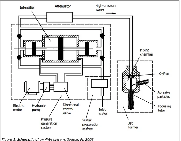
MACHINEA waterjet cutting machine can be divided in several different sub-systems: as schematized in figure 1, a water preparation system, a pressure generation system and a jet former are required to produce the high pressure jet used for cutting the material (Pi, 2008).
The water preparation system is used to pre-treat the inlet water in order to meet the quality requirements and reduce wear of the components in both the pressure generation system and the jet former. Suspended solids in the water can impact the orifice, causing premature wear, while dissolved solids can precipitate out of solution. On the other hand, water that is too pure also causes problems, since it tends to dissolve the materials it comes in contact with (xinology.com, 2014). Water should therefore be treated with appropriate equipment: softening, deionization or reverse osmosis are all processes that can be used to pre-treat the water according to the quality of the original supply (WARDJet Inc., 2014a). Another factor that must be taken into consideration is the water temperature, since the water warms up when it is pressurized. In warm locations, this may represent a problem, and a chiller system is required to reduce the temperature (to approximately 20 °C) and thus slow down pump’s wear (xinology.com, 2014). Finally, a last task that may be carried out in the water preparation system is the addition of polymeric additives to the water to improve the jet characteristics. Although promising, this last technique is not widely adopted for AWJ machining, since concerns exist about the mixing of the abrasive in the water jet (Kulecki, 2002; Louis et al., 2003);
The pressure generation system includes an electric motor with an output power that lies in the range between 20 kW to 200 kW driving a pump that increase the pressure in a separate hydraulic system. This pressure moves a cylinder (named intensifier) that raises the water pressure up to the required level, usually in the range between 300 and 600 MPa (Lorincz, 2009). In some intensifier designs, the alternate motion of the cylinder causes excessive pressure fluctuations, that must be dampened through a tank with approximately 2 liters of capacity, marked “attenuator” in figure 1 (Arleo, 2010); alternative pump designs, with direct drive and no need for attenuators are also possible (Pi, 2008);
Figure 1: Schematic of an AWJ system. Source: Pi, 2008
In the jet former (also named cutting head) the high-pressure water is forced through an orifice, producing a high-speed jet of water. At this point, the abrasive material is introduced, together with some air, inside the mixing chamber, where the abrasive particles are accelerated by the high-pressure water before the water-abrasive jet enters the focusing tube (or nozzle) to be directed towards the workpiece. The cutting head include several parts that are subject to wear and tear, such as orifice and focusing tube, and they must therefore be replaced at intervals that depend on various factors, such as water quality, accuracy requirements and materials used: orifices can be made of sapphire, ruby or diamond, with lifetime varying consistently between the different materials, while nozzles are usually made from carbides and can be affected, among other factors, by type of abrasive used.
For machining operations, the cutting head is mounted on a CNC system that allows to control in details all the different parameters. With a properly dimensioned system, it is possible to mount two or more cutting heads powered by the same pump on the same CNC machine, usually achieving better economies (Pi, 2008).
Two other subsystem must be mentioned, in addition to those indicated in figure 1: the catcher and the abrasive supply system. The catcher is a container that has the purpose of collecting the water and abrasive jet after it passes through the workpiece: since the jet still retains much of its initial energy, the catcher must contain some kind of absorbent material in order to slow down the jet without damage. Typically, water with a depth of at least 60 cm is used as absorbent material, but other catcher designs have been developed for mobile applications (Kulecki, 2002).
Finally, the abrasive supply system is designed to provide the right amount of abrasive in the mixing chamber and it is usually computer-controlled to provide an optimal value of the abrasive mass flow (Henning and Westkämper, 2006; Zeng and Munoz, 1994); Holmqvist and Honsberg (2007) developed a model which ties the optimal abrasive mass flow to the water flow through the abrasive/water ratio, which usually lies around 0,2.
Typical abrasive mass flow rates range from 0,1 kg/min to 1 kg/min (waterjets.org, 2014). Water consumption depends on the pressure and diameter of the orifice, and typical consumption ranges from 1,9 liters/min to 4,7 liters/minute (xinology.com, 2014). These values for the water consumption are comparable to the ones of a common household tap and well explain why it is not usually considered to be a problem in the waterjet industry.
From a cost perspective, garnet is by far the largest component of the operative cost, with a share that different studies set in the range between 50% and 75% (Babu and Chetty, 2006; Hashish, 1983; Hoogstrate et al., 2006; Kurd, 2004). Nozzle and orifice costs account respectively for approximately 3% and 1%, while water cost is only responsible for 1,3% of the total (Hoogstrate et al., 2006);
2.3 A
BRASIVE CHARACTERISTICSAs mentioned above, the abrasive material plays a key role in the AWJ cutting processes, significantly influencing its cost, performances and reliability. This is not surprising, since the whole cutting power of an AWJ derives entirely from the cumulative effect of the impact of a large number of abrasive particles on the workpiece. This process is known as abrasive erosion and has been examined in a large number of studies in an attempt to obtain a reliable model that could be applied to AWJ cutting: most of these
models also include some elements regarding the characteristics of the abrasive particles (see as example Hashish, 1987, 1984) or the more recent Gent et al., 2012);
AWJ cutting performances vary with the material, and different and optimized erosion models have been developed for different types of material, such as metals (Hashish, 1984), ceramics (Zeng and Kim, 1996) or composites (Wang and Guo, 2002). Despite the large amount of research, the abrasive erosion process is still not completely understood, and while the studies contributed to an accurately describe the effect on the cut of machine parameters (such as traverse rate and pressure) it is still unclear which is the effect of the abrasive characteristics such as hardness, shape or particle size. Generally speaking, the harder the material that needs to be cut, the slower the speed and the larger the abrasive consumption, while coarser abrasive allows to achieve faster cuts, but increase the surface roughness (Gent et al., 2012).
However, the lack of a comprehensive scientific model describing the influence on the cut of the physical characteristics of the abrasive particles has not prevented the AWJ industry from building up a list of abrasive qualities that are commonly requested to a good abrasive material (waterjets.org, 2014):
• Hardness is often considered the most important requirement of an abrasive material, since the depth of cut increases with it. On the other hand, this increase can only be observed up to a certain value of the ratio between abrasive and workpiece material hardness (Hashish, 1983); • Sharpness of the particles is also considered an important characteristics, since particles with
sharp edges offer better performances compared to more rounded particles (Gent et al., 2012; Hashish, 1983);
• High density (specific weight) is considered an advantage, since heavier abrasive particles can hit the workpiece with more energy (Gent et al., 2012);
• Consistent particle size of the abrasive implies that most of the larger and smaller particles have been removed. This is a desirable quality, since both can cause problem such as nozzle plugging and inefficient cutting (Ohman, 1993); Moreover, the particle size distribution is able to influence the cutting performances (Momber and Kovacevic, 2000).
• Purity of the abrasive is another desirable quality, since softer or harder particles in the abrasive may lead to reduce performances or increased nozzle wear (Ohman, 1993);
• Price is another fundamental factor that must be considered in the choice of abrasive, being responsible for a percentage that varies between 50% and 75% of the total operative costs (Babu and Chetty, 2006; Hashish, 1983; Hoogstrate et al., 2006);
• Low free silica content in the abrasive is finally another advantageous characteristics of waterjet abrasive, since inhalation of silica particles may lead to silicosis, a serious lung disease. Even though the waterjet cutting process in itself produces little or no dust given its wet characteristics, additional precautionary measures should still be taken during the life cycle of the abrasive if this contains high levels of free silica.
2.4 A
BRASIVE MARKET AND GARNET PRODUCTIONEven though a large number of materials presents all the aforementioned characteristics, the abrasive market seems to be dominated by a single, specific abrasive: almandine garnet, a naturally inert mineral, with a hardness of between 7,5 and 8,5 on the Mohs scale and a density of 3,9 to 4,1 g/cm3.
Almandine garnet generally occurs in schists and gneisses or in placer deposits derived from these rocks. The latter are the source of the majority of the world’s production, since garnet occurs as sand or gravel that with a concentration of approximately 30% and can be easily mined (NSW Department of Primary Industries, 2007; Olson, 2000) either alone or together with other minerals such as ilmenite, rutile and zircon (VV Mineral, 2014). Extracting the garnet through blasting and crushing the rock is also possible and usually this method produces a higher quality abrasive, since the particles have sharper edges compared to the alluvial garnet which has been subject to erosion. After the extraction, the garnet is sifted and divided into different particle sizes. For waterjet cutting applications, these range from 425 µm (for faster cuts with reduced precision) to 125 µm (for minimum tolerances), with most applications carried out with an average particle size of approximately 200 µm.
A survey carried out in 1994 among a sample of waterjet users (with a strong prevalence of North American users) showed that 90% of the survey respondents used garnet at least some of the time, with most of the high volume users using exclusively garnet (Mort, 1995); the large adoption of this abrasive material has been also confirmed for the Scandinavian market in recent times (Bengtsson, 2014).
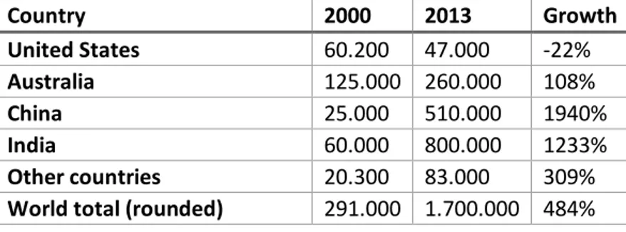
Even though garnet is a common mineral, large economically viable deposits of high-quality garnet are relatively rare, and the production is concentrated in a limited number of countries: in 2013, approximately 1.700.000 tons of raw garnet were mined worldwide, with a sharp increase since 2010, when garnet production was estimated in 291.000 tons (Olson, 2002). The growth is in large share due to the manifold increase of the production in China and India, as shown in table 1:
India is the single largest garnet producer, with a production of approximately 800.000 tons, followed by China (510.000 tons), Australia (260.000 tons) and United States (47.000 tons). Other countries (like Russia and Turkey) only contributed for 83.000 tons, mainly destined to internal use (Olson, 2014). Only 55% of this amount is considered to be suitable for the market after the refining process, with AWJ industry being the single most important end user in the United State, accounting for approximately 35% of the refined garnet. Other uses include blasting (30%), water filtration (20%) and abrasive powders (10%) (Olson, 2014).
Table 1 also shows how garnet production is highly concentrated in a handful of countries, with little or no garnet produced in Europe. As a consequence, waterjet operations must rely entirely on garnet supplies originating in India, Australia, China or the United States, with transport and logistic operations contributing for a large share to the cost and the environmental impact of waterjet cutting.
The Scandinavian market (including Denmark, Finland, Norway and Sweden) imported approximately 16.000 tons of garnet for different uses, mainly from India and United States. Sweden alone imported approximately 8000 tons of garnet (Bengtsson, 2014).
Table 1: Garnet production in tons, per country. Based on data of Olson (2014, 2002).
Country 2000 2013 Growth United States 60.200 47.000 -22% Australia 125.000 260.000 108% China 25.000 510.000 1940% India 60.000 800.000 1233% Other countries 20.300 83.000 309%
World total (rounded) 291.000 1.700.000 484%
2.4.1 Alternative abrasives
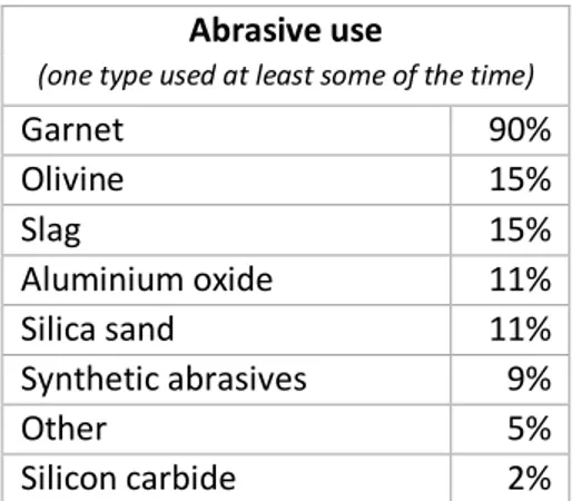
As mentioned above, even though almandine garnet seems to be the preferred choice when it comes to waterjet abrasives, a certain number of other materials present most of the characteristics listed in section 2.3. In the survey realized by Mort (1995) a detailed overview of the abrasives that are most used in the industry is given. As reported in table 2, garnet is by far the most used material, followed by olivine, slag, aluminum oxide and silica sand. Other synthetic abrasives (such as crushed glass) also played an important role.
The scarce utilization of most of the abrasives reported in table 2 can be ascribed to different factors: generally speaking, olivine, slag, silica sand and crushed glass are cheaper than almandine garnet, but they are considered to be less effective. Aluminum oxide and silicon carbide are instead scarcely used for opposite reasons: they are sharp, hard and very aggressive and therefore can be used for high cutting performances, but they are also more expensive than garnet and cause an increased wear of the nozzle and mixing chamber. As a result, cheaper abrasives are usually employed whenever the variable costs of abrasives is more important than a high production rate, while more expensive abrasives are only used for applications where the cutting performance is critical (Kulecki, 2002).
Even though the industry expresses a clear preference for almandine garnet over other materials, Gent et al., (2012) notes the low acceptance of some of the alternative abrasives may be in some cases based on wrong assumptions or partially unjustified. The same authors also point out how the results of the existing research on alternative abrasive varied considerably depending on the material cut and the test parameters, and how all AWJ models currently in use have been developed using garnet. On the other hand, for some applications alternative abrasives displayed good capabilities in a number of researches: olivine was successfully used for cutting glass (Martinec et al., 2002) and showed a reduced surface roughness when compared to garnet (Hloch and Valíček, 2007) while high-density crushed glass demonstrated good performances when cutting aluminum (Gent et al., 2008). Finally, also some non-almandine garnet minerals showed satisfying performances when tested by Engin et al., (2011).
Alternative abrasives such as olivine or crushed glass may also be employed for cutting composites and other softer materials, where their reduced hardness compared to garnet may still be sufficiently high to guarantee optimal performances with the positive addition of preserving the focusing tube. Even though the idea of alternative abrasives for softer materials seems to be present to some extent in the industry (waterjets.org, 2014) and in some cases it is translated into current practice (Bengtsson, 2014) no studies were found in the scientific literature investigating the behavior of alternative abrasives on softer materials.
Given the scarce knowledge about the actual performances of alternative abrasives and their promising results for some applications, one could argue that a certain share of the actual waterjet application may be switched from garnet to other abrasives maintaining acceptable performances.
Table 2: Abrasive use, each abrasive used at least some of the time.
Based on data by Mort (1995).
Abrasive use
(one type used at least some of the time)
Garnet 90% Olivine 15% Slag 15% Aluminium oxide 11% Silica sand 11% Synthetic abrasives 9% Other 5% Silicon carbide 2% 10
The usage of alternative abrasive materials could, in some cases, also imply a reduction of the environmental impact: this is especially true for those materials that can be produced from recycled materials (such as crushed glass) or as a byproduct of other industries (like slag). Given the distance of the main production sites of almandine garnet and the resulting emissions due to its transportation, the possibility to use other non-almandine garnet minerals mined in Europe could also be worthy, at least for the European waterjet industry.
Another alternative abrasive that may sensibly reduce the environmental impact of waterjet operations is olivine: this mineral is extracted in large quantities in Norway, which is by far the world largest producer (Norwegian Ministry of Trade and Industry, 2013) thus limiting the emissions related to transportation, at least for AWJ operations located in Scandinavia. Olivine is also one of the silicate minerals that can be used for CO2 capture and sequestration making use of the carbonation reactions that naturally happen
during the weathering process of this type of minerals. Indeed, the olivine (and similarly other silicate minerals) reacts with carbon dioxide in presence of water, forming a stable carbonate and thus effectively storing the CO2. However, this process normally takes place over a geological time scale, and thus it needs
to be sped up in order to have any practical applications. However, carbon sequestration through mineral carbonation has been proposed since the 1990 as a method to absorb CO2 from the atmosphere to reduce
the greenhouse effect (Seifritz, 1990), and among the different techniques that have been proposed to accelerate the natural weathering process, grinding olivine into small-sized seems to be one of the most promising, with ample research on the topic that can be found in the literature (see as example Haug et al., 2010; Kleiv and Thornhill, 2006). Once the olivine has been reduced to a suitable particle size, the reaction is much faster, and complete dissolution can be achieved in a reasonable time scale if the material is placed in an acidic environment; some even propose that the olivine could be simply spread in shallow seas to achieve a complete dissolution within a time horizon that can be estimated in years, even if the actual dissolution rate under this conditions is still object of debate (Hangx and Spiers, 2009; Schuiling and de Boer, 2011). This solution has yet to find any concrete application, with the costs related to the olivine extraction, transportation and grinding representing the main obstacle (Newall et al., 2000). On the other hand, if a similar solution is considered in symbiosis with waterjets operations, this could result in a much easier application, since the olivine would be already reduced into small particles.
2.5 M
ANAGEMENT OF THE WASTE FLOWSFor most applications, the waste flow from AWJ doesn’t present any specific hazard, and can thus be treated as regular waste: after having allowed most of the suspended particles to settle, wastewater is therefore run through the sink, while the abrasive sludge is removed from the catcher, either by hand or through an automatic system.
As the water jet cuts through the workpiece, it removes small particles of material that end up in the bottom of the catcher together with the spent abrasive. Therefore, the abrasive sludge also contains a small amount of particles of the workpiece material, in a concentration that can vary from 0,5% to 5% in weight (Kurd, 2004; Louis et al., 1995), with the exact value changing with the process parameters: rough cuts require less abrasive compared to precision cuts to remove the same amount of material, which is proportional to the kerf width, workpiece depth and length of the cut. Moreover, the specific gravity of the machined material also plays an important role if weight percentages are considered. Depending on the value of the material cut, the metal particles mixed with the abrasive may reach a concentration that
makes their recovery an economically attractive alternative: this is especially true for precious metals like gold or platinum (Volpe, 2010).
The particle size of the removed workpiece material is usually smaller than original size of the abrasive, but only slightly smaller than the abrasive size after the cutting process, and it is influenced by the quality of the cut (quality cutting causes smaller particles than rough cutting) and, to a minor extent, from the type of abrasive used (Louis et al., 1995).
Once the spent abrasive material has been removed from the catcher, a number of option are viable for its treatment. These can be organized in a number of different categories that are similar to those defined by Urbánek (2001):
• In-site recycling: the abrasive material is processed by a dedicated machine in the same workshop, and it is reused for waterjet cutting operations.
• Off-site recycling: the abrasive is placed to dry and it is then sent in a separate process facility for recycling for waterjet cutting or other similar applications.
• Recycling for other uses: the abrasive material is dried and sent in a separate process facility to be employed in other non-waterjet uses, such as raw material for bricks, asphalt or concrete production.
• Landfilling: the spent abrasive is handled to a waste hauler and it is disposed in a landfill.
In practical application, a large predominance of the last option has been observed, with approximately 80% of the abrasive used in Scandinavia ending up in landfill right after the first use (Bengtsson, 2014); the remaining fraction is usually recycled in a separate process facility, while the two remaining options are only sporadically chosen.
Since garnet and most of the other abrasives in use are inert, the characterization of the solid waste from waterjet cutting is entirely dependent upon the composition of the workpiece material that has been processed. However, most of the materials that are usually cut with waterjets do not present any hazard and therefore the solid waste for waterjet operations can usually be landfilled as inert waste, even if sometimes high contents of specific substances (such as copper), although below the limits, may suggest landfilling as non-dangerous waste instead (Gustafsson and Nayström, 2009);
The classification of the spent abrasive as inert waste makes its landfilling an economically attractive option (Lauritzen, 2014). Moreover, this solution allows to drastically reduce the transportation distance. Special treatment of the waste flows becomes instead needed when the machined workpiece is made of hazardous materials, such as lead. In this case, landfilling of the waste represents an important cost, since it can no longer be considered inert and thus it is subject to a strong taxation. In order to avoid this, the concentration of the hazardous material in the waste must be reduced, either removing the fragments or mixing the polluted abrasive with fresh material. Although the first option is preferable from an environmental perspective, the second could present some economic advantages if the pollutant is present in low concentrations that are very close to the limit set by the law.
2.5.1 Alternative recycling and disposal practices
As mentioned above, a certain share of the abrasive used in Scandinavia is recycled, either as waterjet abrasive or as raw material for other industries. Given the importance of the abrasive cost, a large amount
of efforts, both from the academia and the industry, has been directed towards the possibility of reusing the spent abrasive, analyzing the problem from several different perspective.
The recycling process for an abrasive material used for waterjet operations essentially involves a separation of those particles that still maintain suitable characteristics from the fragments of the workpiece material and the abrasive particles that have broken down in the cutting process, resulting in a size that is too small to be effectively reused. For this reason, several studies have been carried out to understand the mechanism of particle fragmentation in waterjet cutting. A number of authors (Galecki and Mazurkiewicz, 1987 as in Pi, 2008; Guo et al., 1992; Labus et al., 1991; Ohlsen, 1997) noted that a large number of the particles did not fragment in the impact with the work material but in the mixing process, with the exact number depending on a number of process parameters. Junkar et al., (2003) further analyzed this phenomenon, concluding that most of the abrasive fragmentation takes place for rebounds against the focusing tube in the acceleration phase, when the difference of velocity between the waterjet and the abrasive is highest.
A number of studies demonstrated the feasibility of abrasive recycling for different kind of commercial garnet and under different conditions, with the recycled abrasive often showing better performances. Ohlsen (1997) analyzed the possibility of recycling Barton garnet, noting that recharged abrasive has better performance than the new one if the particle size distribution is carefully chosen. Babu and Chetty (2003, 2002) evaluated positively the usage of recycled Indian garnet, both alone and recharged with fresh abrasive, resulting in increased waterjet performances if particles smaller than 90 µm are discarded and achieving high recycling rates. The recycling capability of GMA Garnet (from Australia) was positively evaluated by Pi et al. (2009). The recycling of Supreme garnet (from India) was also examined in (Pi et al., 2012), with results in accordance with the studies of Babu and Chetty (2003); Aydin (2013) developed a model for the abrasive recyclability when cutting granite. In every case, the percentage of abrasive that could be recycled was consistent, ranging from 50% to 80%, and using recycled abrasive did not have any detrimental impact in most cases, but resulted instead in slightly better performances. These improvements can be attributed to a better particle size distribution, sharpened particle edges or reduced amount of impurities in the recycled abrasive.
From an economical perspective, (Kretschmer and Aust, 1999) concluded that, for a recycling system to be convenient, the share of reusable abrasive ranged from 15% to 40%, well below the recycling capability observed in the studies above. Pi (2008) estimated an increase in the profit ranging from 20% to 38% if abrasive is recycled or recharged to some extent.
Because of its relative simplicity, abrasive recycling does not require any particular equipment and can be carried out directly on the shop floor, integrating the abrasive removal system of the waterjet machine with a recycling unit. Nonetheless, at the present time only a limited number of manufacturers offers a recycling unit, and the choice seems to be restricted to a handful of models available on the market. Even if with different design choices, all the models on the market offer an optional patented nozzle to remove the abrasive material from the catcher tank and transport it to the recycling unit, where the spent abrasive is screened, separating the reusable abrasive from the workpiece material and the undersized particles. The moist reusable fraction is then conveyed to a drying unit, where the abrasive is dried by a number of electrical resistances. After the drying process, the abrasive is then screened a second time to remove any large particle and it is then placed in a container, ready for being used again (Kurd, 2004). Some recycling units optionally offer the possibility to separate the recycled abrasive into coarser and
finer particles for different uses (WARDJet Inc., 2014b). The residues of the process, usually composed by fine particles and fragments of the workpiece, is generally landfilled. Since the concentration of fragments in the waste sludge is higher than in the rest of the abrasive, recovering the fragments may be economically viable. On the other hand, if the workpiece material presents some kind of toxicity, but this is beneath the limits set by the law, the recycling process may elevate the concentration of toxic compounds above the limits, significantly increasing the recycling costs.
Direct abrasive recycling on the shop floor does not seem to be a common option, and the scarce diffusion of this technique may have a number of different reasons: among the others, a large number of concerns exist about the quality of the recycled abrasive, the fraction that can be effectively recovered and the reliability of the recycling machine. Also, the size of the available models and the large initial investment required make the process convenient only for large abrasive consumption. Because of the design of the recycling process, this machines cannot be used if the cutting pressure is particularly high or if the workpiece material is made of wood, plastic or easy melting composites (WARDJet Inc., 2014b). Finally, the workshops may just not be willing to go through the possible hassles of taking care of the spent abrasive, preferring to delegate this task to specialized companies.
A second solution for abrasive recycling, that possibly overcomes all the limitations mentioned above, is the recycling in a dedicated facility, that also processes garnet for blasting or other uses: in this case, the larger scale allows the use of the same machinery designed for abrasive refining in a mining context, limiting the influence of possible disturbances and perhaps increasing the process efficiency. This kind of plants usually also handle abrasive used for blasting, and can produce abrasive of different particle sizes for different operations. On the other hand, large investments are still needed and they can only be justified if the plant can collect a large amount of suitable abrasive from users in the vicinity. Moreover, depending on the abrasive origin and usage, quality concerns may raise as well as issues related to the amount and typology of the impurities contained in the abrasive. Finally, this solution still involves a transport phase between the abrasive user and the recycling facility, reducing the benefits that can be obtained from this practice and often making it economically inconvenient. For all these reasons, the number of plants recycling abrasive is very limited, and only one facility is currently operating in Scandinavia (GarnetGreenline, 2014).
Finally, a last possibility for recycling of the spent abrasive involve its use for a number of applications as construction material: usage of waterjet abrasive as a filler or as concrete constituent was positively evaluated by Mathews (1998), while a large number of papers exists in the literature regarding the usage of recycled sandblasting abrasive in construction applications (see as example Heath and Nelson, 1998; Sua-iam and Makul, 2013; Webster and Loehr, 1996). Even though no specific data is available, this solution is effectively applied in Scandinavia, although only for a small fraction of the abrasive, with the material used for the production of bricks (Bengtsson, 2014); yet, in this case, the spent abrasive only replaces relatively inexpensive and widely available material without exploiting any of the specific characteristic of waterjet abrasive and thus the benefits of this practice are limited.
3 T
HEORETICAL FRAMEWORK
During this study, the problem described in chapter 1 has been approached from a specific perspective that makes use of a number of concepts, theories and tools lying within the field of the environmental engineering that proved to be particularly applicable in this specific case and that have therefore served as a guidance throughout the duration of the whole study.
In this chapter, the most relevant concepts of these theories will be outlined, also clarifying their linkage to the analysis of the material flows in the AWJ industry and explaining how they have contributed to the realization of the present paper.
3.1
I
NDUSTRIAL ECOLOGYIndustrial ecology is an emerging science that merges together different disciplines and whose formal definition is still object of debate (Allenby, 2006; Lifset and Graedel, 2002; Seager and Theis, 2002). Its origin can be traced back to the characterization of industrial ecosystem used by Frosch and Gallopoulos (1989) and implies the study of an industrial system not in isolation from its surroundings, but rather in concert with them, to achieve and maintain sustainability (Graedel and Allenby, 2009). In such a system “the consumption of energy and material is optimized, waste generation is minimized and the effluents of one process serve as the raw material for another process” (Frosch and Gallopoulos, 1989); a key concept of industrial ecology is therefore the rejection of the idea of waste as useless or worthless material, replaced by a vision inspired by the biological systems, where nothing is eternally discarded and all materials are reused in various ways (Graedel and Allenby, 2009). Biological organisms and industries alike utilize resources and emit a variety of waste products, but million years of evolution have ensured that the firsts can carry out this task in a way that is way more efficient than the seconds. In this sense, industrial ecology is a mean by which one seeks to optimize the total material cycle, ideally achieving a close loop where no waste is created.
Analyzing from this perspective the material flows within the AWJ industry, it appears evident how they are today prevalently unidirectional, with the raw material extracted from the heart crusts and transported for thousands of kilometers only to be discarded right after first the use. In this sense, industrial ecology provides a number of tools and suggestions for improving this process
3.2 E
NVIRONMENTAL SYSTEM ANALYSISAs mentioned in the previous section, an important characteristic of industrial ecology is its comprehensive approach to the study of an industrial system. As expressed by Seager and Theis (2002), “if the boundaries of a system expand…the most favorable outcome may be found by coordinating the activities of all system components, rather than by combining the best option of each subsystem”; it is therefore important to adopt a holistic perspective when approaching a problem, including not only the product or process itself, but also the related systems.
The expansion of the system can be carried out in many different ways according to the object and the goal of the study, and the boundaries can be set based upon a number of different criteria to include a geographical region, a certain product, a specific substance or an organization (with or without its supply chain), considering or not economic and social aspects and so on. A natural consequence of this variety of
alternatives is that identifying the appropriate system level may be challenging. Moreover, the resulting system often presents an elevate complexity, and modelling the complex interactions between the different subsystem is most often a challenging task.
To reflect this complexity, a large number of tools is available for assessing the environmental impact of different type of systems, each one focusing on different environmental impacts and with different focus on the spatial and temporal dimensions. Different tools are hence only suitable for different circumstances (for a review of the different tools and the situation in which they are appropriate, see Finnveden and Moberg, 2005).
During this study, the boundaries were set to include not only the industry in focus (the AWJ industry) but also the main suppliers (abrasive producers and distributors) and the different entities operating for the management of the waste flows. Moreover, also activities that don’t have any immediate relation with the AWJ, such as the production of construction material or the recycling of glass, have been taken into consideration, in an effort to further optimize the material flows.
3.3 L
IFEC
YCLEA
SSESSMENTThe inclusion in the system of the steps that precede and follow the use of a product or a service implies the assumption of a life cycle perspective for the study. This approach aims at evaluating a product or service not only during its operative life, but also during the extraction of the raw materials, during its manufacturing and finally during all the processes that take place after that it has been disposed as waste. This perspective is at the basis of all modern approaches to environmental issues (Allenby, 2006) and has generated a number of analytical tools that use a life cycle (or cradle-to-grave) standpoint to evaluate the environmental effects of a product or an activity. The most famous and widespread of these tools is the Life Cycle Assessment (LCA), used both in the industry and in the academia for a number of different application ranging from research to support in decision making to marketing of products.
The most common approach to LCA follows a four step methodology consisting of scoping, inventory analysis, impact assessment and interpretation of the results. This methodology is highly standardized, and a number of organization have published standards and manuals intended to provide guidance during the LCA process (see as example EC, 2010a; ISO, 2006). The scoping process begins with a precise definition of the goal that must be fulfilled, followed by the definition of the system boundaries, the impact category analyzed, the choice of a functional unit to be used for comparison and the level of detail which needs to be achieved to fulfill the goal. The second component of a LCA is the inventory analysis (also known as Life Cycle Inventory, or LCI) where all the relevant energy and material flows used throughout the life cycle of a product are mapped (Graedel and Allenby, 2009). This phase requires quantitative data that needs to be directly collected from the process, extracted from the literature or from a specific LCI database containing data from the most common processes. In the third phase, named impact analysis, the outputs to the environment mapped during the LCI are related to the environmental impact they have on the environment, while in the last phase (the interpretation) the findings from the previous stages are used to draw conclusions. This process, although easy to describe linearly, is in reality iterative, and most often these steps must be repeated several time before the final conclusions are reached. Moreover, all the steps are carried out with an accuracy that is proportional to the purpose of the LCA, and therefore large differences can exist between different analysis of a same product or process, resulting in a comparison that is not always easy.
4 R
ESEARCH DESIGN AND METHODS
As described in chapter 2, the abrasive cutting process only involves a limited number of substances: water, abrasive and the workpiece material that needs to be cut. No chemical reaction is involved in the process, and the materials that were introduced as an input are discharged with only minimum transformations. A schematic of the material flows through a waterjet cutter is depicted in figure 2 below:
Out of these three materials, the abrasive is the one that causes most concerns: from an economical perspective it can represent as much as 70% of the total operating costs (Pi, 2008), while Ny et al. (2009) clearly indicates the abrasive as the material that causes most of the technology’s environmental issues; in comparison, the water flow only causes a minor impact, since the consumption of a waterjet is overall limited and the wastewater does not usually contain any dissolved contaminant, but only a certain amount of suspended solids. Similarly, even in case of a potentially hazardous workpiece material, only the small fragments contained in the abrasive sludge represent a problem, since the finished piece and the scraps of larger size can be collected and handled in ease.
For all these reasons, the flow of abrasive material can be considered, on a first approximation, representative of the environmental impact of the AWJ process as a whole, and it has been therefore placed in focus during this study. This approximation is especially valid if it is observed that many other flows (such as water or energy) can, if necessary, be linked to the abrasive flow with a fixed ratio once the operative conditions have been set.
The abrasive flow has then been analysed using an LCA methodology, iteratively repeating the steps listed in section 3.3 until a conclusion in accordance with the aim of the study was reached. For this process, the LCA software SimaPro (PRé Consultants, 2011) was employed, and data from the Ecoinvent (Swiss Centre for Life Cycle Inventories, 2010) and ELCD (EC, 2010b) LCI databases has been used whenever information
Figure 2: Schematic of the material flows through a waterjet cutting machine.
Waterjet
Water
Abrasive
Wastewater
Abrasive sludge
Raw
material
Finished
piece
17from the specific process was not available. In the following sections, the operations and assumptions that have been made in each step will be described, while a complete overview of the data used as input is available in appendix I.
4.1 S
COPE DEFINITIONAnalysing the abrasive life cycle, it is clear that this can be conceptually divided into three phases taking place before, during and after its usage in the waterjet. With this division, the first stage involves the abrasive production (whether mining it from the ground or manufacturing it in an industrial facility) and its transportation to the location where it will be employed in an AWJ machine. The operations taking place within the workshop are considered to be the use phase, while the last stage includes all those processes aimed at disposing of the spent abrasive sludge after it has been removed from the waterjet catcher, including eventual efforts for recycling it. This process is represented in figure 3:
Since the focus of this analysis is on the abrasive material, the functional unit for the LCA was chosen in direct relation with its mass flow. Other alternatives, such as a functional unit based upon the operative time or one related to the value added to the workpiece, were also evaluated, but this choice presents several advantages: on the first place, relating the functional unit to the mass of abrasive allows an easy comparison between different production processes and disposal practices; moreover, the abrasive mass flow can be directly linked to other quantities such as water, electricity consumption and operational time once the operative conditions in the specific case have been defined. The reference flow was therefore fixed as one metric ton (dry weight) of abrasive material.
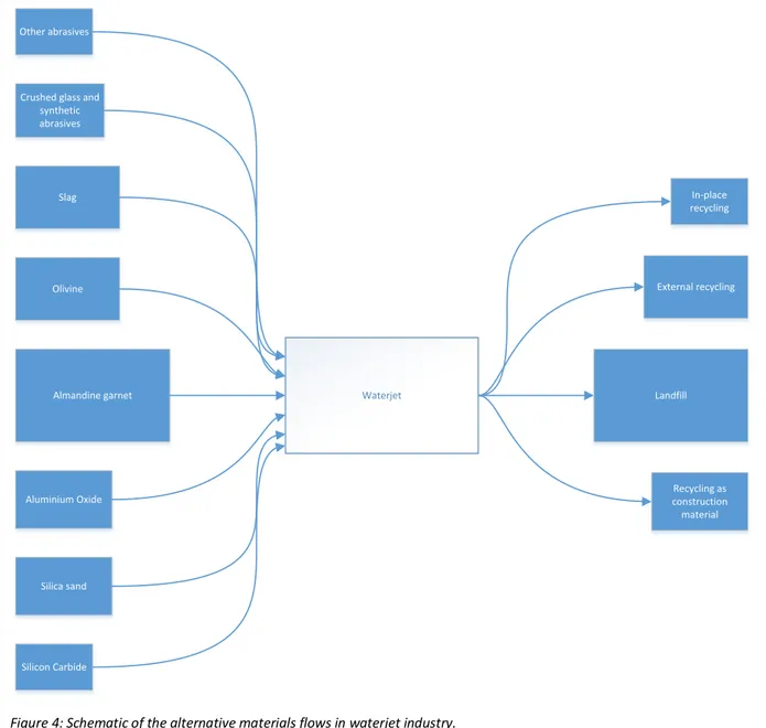
As described in section 2, the large majority of waterjet operations are carried out using garnet as abrasive material and disposing of the solid waste in a landfill after the use; there are, however, a number of other alternatives which deserve to be investigated since, as mentioned in section 3.2, the best solution may be found combining activities from different interrelated systems; hence, in accordance with the aim expressed in section 1.2, a number of other alternatives regarding both the choice of abrasive and its disposal have been selected from the options presented in sections 2.4.1 and 2.5.1, with the purpose of developing a set of scenarios to be compared with the current practice: a more detailed description of the criteria used for this process is reported in section 4.1.1. However, every scenario includes in the system boundaries all the three phases mentioned above, defining them as follows:
• The production phase includes the retrieval of the raw material, whether from the lithosphere or technosphere, all the processes needed to transform the raw material into a suitable abrasive and its transportation to an AWJ workshop located in Scandinavia.
Figure 3: Life cycle of an abrasive material.
Usage in waterjet Removal from the catcher Transportation
Production Transportation Recycling or disposal
Production phase Use phase Disposal phase