This is the published version of a paper published in .
Citation for the original published paper (version of record):
Abdoli, S., Semere Tesfamariam, D. (2014)
Investigation on Machine Tools Energy Consumptions.
International Journal of Mechanical, Aerospace, Industrial and Mechatronics
Engineering, 8(6): 1136-1143
Access to the published version may require subscription.
N.B. When citing this work, cite the original published paper.
Permanent link to this version:
Abstract—Several researches have been conducted to study consumption of energy in cutting process. Most of these researches are focusing to measure the consumption and propose consumption reduction methods. In this work, the relation between the cutting parameters and the consumption is investigated in order to establish a generalized energy consumption model that can be used for process and production planning in real production lines. Using the generalized model, the process planning will be carried out by taking into account the energy as a function of the selected process parameters. Similarly, the generalized model can be used in production planning to select the right operational parameters like batch sizes, routing, buffer size, etc. in a production line. The description and derivation of the model as well as a case study are given in this paper to illustrate the applicability and validity of the model.
Keywords—Process parameters, cutting process, energy
efficiency, Material Removal Rate (MRR). I. INTRODUCTION
UE to increasing in sustainable production attitude, energy efficiency has been point of interest in most of the industries including manufacturing, which eventuate considerable amount of research in this area.
It has been established that the share of cutting process is considerable out of total consumption [1]. Small percentage saving on consumption brings a significant reduction in overall energy consumption and manufacturing cost.
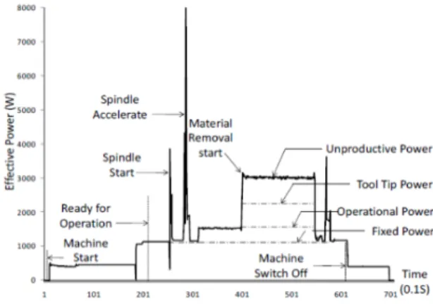
A close observation to the machine energy consumption profile, like the one shown in Fig. 1, illustrates the variation in the consumption as the operation goes to different states, idle, setup, start of cutting, cutting, etc. [2]. Thus the profile is very much dependent on factors related to planning and cutting conditions. Hence, this kind of profile showing consumption with respect to the corresponding states of machining system holds essential information which can support process and production planning.
Developing an energy consumption model for characterizing Machine Tools Energy Consumption (MTEC) helps to analyze the estimated energy consumptions with respect to the influencing factors such as cutting conditions and machine type. We aim to formulate the energy consumption of machine tools as the function of cutting parameters (cutting depth, spindle speed and feed rate). This model can be undertaken as a decision based framework for process and production planning in real manufacturing systems.
S. Abdoli is with the Royal Institute of Technology, Stockholm, Sweden (e-mail: abdoli@kth.se).
D. T. Semere is with the Production Engineering Department, Royal Institute of Technology, Stockholm, Sweden (e-mail: danielts@kth.se).
Fig. 1 Energy profile of a turning machine II. MOTIVATION
MTEC has been a topic of interest for investigation regarding energy saving measures in order to minimize the production cost or to fulfill objectives towards green and sustainable manufacturing perspectives. A number of research works have been conducted and various results have been proposed as described in the next section. High level of complexity in existing MTEC models, limits their applicability in production floors. This research is motivated to accomplish a practical model for appraising MTEC in terms of process parameters.
In a wider perspective, this work is towards integrating energy and cost minimizing measures to the overall production processes, i.e., for any energy and cost saving measures to be effective, it has to be integrated into the process and production planning activities. To realize this, the behavior of the resource consumption profile as a function of the states resource undergoes, should be captured and modelled.
For a process planer, the effect of cutting parameters on energy consumption in all machine states is a useful input during selection of the process parameters and quantifying the environmental footprints of the product or manufacturing system. Similarly for production planning, the energy consumption profile as a response to the state changes is a crucial information in setting production planning parameters like batch sizes and setting production schedules.
Related Work
MTEC has been studied using various methods in terms of cutting force or thermal equilibrium in machining process. Some research studies have been done to investigate the energy consumption of the different machine’s units. Diaz shows that in Mori Seiki NV1500DCG milling machine, servo and spindle motors have the biggest share of energy consumption in idle state [3]. Mori suggests general tips to
Shiva Abdoli, Daniel T.Semere
Investigation on Machine Tools Energy Consumptions
D
reduce energy consumption such as setting the cutting conditions in such a way that it reduces machining time or synchronizing the spindle acceleration and deceleration with feed system at rapid traverse stage [4].
Draganescu proposed a model to calculate metal cutting state consumption based on cutting power, machine tool efficiency and material removal rate [5].More practical consumption model developed by Kara as a function of material removal rate and cutting volume [6]. Rajemi presented a model to calculate MTEC for all machine states separately, based on power demand by machine modules, energy requirement in cutting operation and material removal rate. He also considered tool life in its model to calculate energy consumption in tool changing state [7]. Y. He developed a comprehensive model to calculate the consumption for the whole machining operation. In that work CNC codes were used to specify state transition. The proposed model is based on power requirement and time interval in each state [8].
III. APPROACH
There are a wide variety of options in order to measure MTEC including current flow and voltage measurement from wires of the electricity main supply. Measuring devices such as digital clamp meters in conjunction with DAQ (data acquisition system) enables a continuous record of machine power demand. Exploiting interacting software’s with real-world (e.g. Matlab or Labview) enables to interpret raw data and demonstrate MTEC variation with respect to machine state transitions.
A structured design of experiments (DOE) such as Response Surface Method (RSM) ensures sufficient and comprehensive experiments which enables understanding the effect of variables manipulation on results (MTEC in this research). Statistical analysis on MTEC measurements in different experiments gives the opportunity to propose the final mathematical model of MTEC depending to input variables (cutting parameters here).
Process planners can effectively utilize these kinds of models in order to estimate the effect of changing process parameters on MTEC in different states. This also provides a test bed for production planners to analyse the long term effect of changing cutting parameters and production strategies on related indexes and criteria.
IV. CASE STUDY
The machining operations studied in this research are turning and milling as the basic operations of the gear manufacturing process. Turning performs machining on the work piece to reach the required diameter and continues by milling to grove it. Since energy efficiency is the main concern of this research, dry machining is studied in this paper. Due to all limitations for direct measurement on machine tools, (1) is utilized for estimating MTEC in cutting state [6].
/ (1) The SEC is the required MTEC for removing 1 of material from the work piece. and are the machine specific coefficients. To use the proper values for constant coefficients in (1), studied machines in [6],Mori Seiki Dura Vertical5100 for milling and Colchester Tornado A50 for turning, are assumed for machining experiments in this research.
Considering the rough estimation of energy consumption, we tried to find accordance cutting tools and work piece in literatures to increase reliability of the results. Work piece material assumed to be a cold-rolled steel bar. Cutting tool in milling and turning are respectively solid-uncoated cobalt alloyed HSS and TiN coated tungsten carbide triangular inserts [9], [10]. Tested cutting parameters are selected from their practically possible spectrum, considering cutting tool and work piece material. Cutting depth, spindle speed and feed are input variables with two variance levels, shown in Tables I and II, respectively for turning and milling operation. As explained earlier, RSM method used for DOE, which provides dependent experiments for monitoring of the cutting parameters effect on MTEC.
TABLEI
CUTTING PARAMETERS LEVEL IN TURNING EXPERIMENTS
Cutting depth Feed rate Spindle speed
1mm 0.14 mm/rev 425 rev/min
2mm 0.2 mm/rev 500 rev/min
mm = millimeter, rev= revolution, min= minute. TABLEII
CUTTING PARAMETERS LEVEL IN MILLING EXPERIMENTS
Cutting depth Feed Spindle speed
1mm 0.06 mm/rev 390 rev/min
2mm 0.2 mm/rev 450 rev/min
mm = millimeter, rev= revolution, min= minute.
V. ENERGY CONSUMPTION FORMULATION OF CUTTING STATE
A. General Effect of Cutting Parameters on MTEC
Generally the power demand of machine tools can be divided into fixed power rate and variable demand. Fixed demand ensures operational readiness for running basic equipment features and basically depends to machine type [1], [2], [5]. The variable section refers to the operational state energy consumption. This energy enables axis movement, spindle rotation and tool tip power demand and obviously influenced by cutting parameters [2].
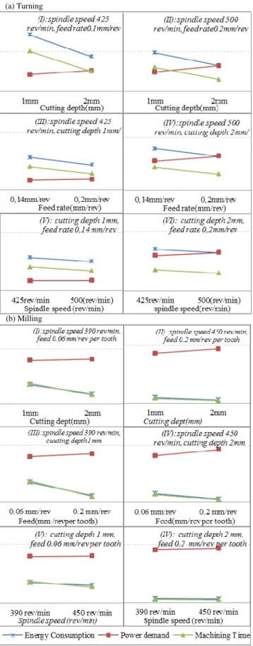
The effect of changing cutting parameter on power demand, MTEC and cutting time, in turning and milling operations has been analyzed. The design settings for the experiment and the results obtained are depicted in Fig. 2. For example in turning, the effect of increasing cutting depth, from 1 to 2 mm, is observed independently in two separate experiments (I) and
(II). In the first one,(I), two non-experimental parameters have
their lowest values (spindle speed 425rev/min and feed rate 0.1mm/rev) whereas in second one (II), they are given their International Journal of Mechanical, Aerospace, Industrial and Mechatronics Engineering Vol:8 No:6, 2014
highest values.
Fig. 2 cutting parameters effect on MTEC in turning & milling operation
All experiments, demonstrate an obvious reduction trend in MTEC by increasing related cutting parameter’s value. Observing Fig. 2 with existing similar pattern in all experiments, reveals that even power demand increases by increasing cutting parameters values, but the gross reduction in machining time, not only covers excessive power demand rate, but also eventuates in reduction of total MTEC in cutting state.
Comparing each two experiments related to one specific parameter (e.g. and II related to cutting depth), the absolute reduction in MTEC slope is bigger when non-experimental parameters have low values, comparing with the case when they have high values. This means, if all 3 cutting parameters have high values, reducing one factor won’t increase MTEC considerably. On the other hand, if all parameters have low values, increasing one parameter constitute an impressive reduction in MTEC. This result can be greatly helpful, if selection spectrum for one parameter is limited due to some reasons. For example in the feed rate selection, lower values are more preferred because of its direct influence on surface quality especially in finishing operations.
A. Effect of Cutting Parameters on MTEC
Regression method is used for analysing the results and for formulating MTEC in cutting state. MRR represents all parameters simultaneously, hence, cutting time and MRR are considered as independent variables. The regression equations for turning and milling are shown in Tables III and IV, respectively. In given equations, X refers to MRR, t to machining time and Y is estimated energy consumption. Correlation coefficient calculated for each equation [11].
Tables III and IV show the second degree polynomial equation for turning and third degree polynomial equation for milling have highest correlation coefficients and sufficiently fit to estimate MTEC for turning and milling operations. The final models are given in (2) and (3) for turning and milling respectively.
TABLE III
REGRESSION EQUATIONS FOR ESTIMATING MTEC IN MILLING OPERATION
Regression equation Correlation coefficient
Y=(1.4 +64.5)×t 0.985
Y=(-0.023 +1.619 +64.14)×t 0.998
Y=(-0.001 -0.002 +1.5 + 64.23)×t 0.9999
Y=(64.42× . )×t 0.8915
TABLE IV
REGRESSION EQUATIONS FOR ESTIMATING MTEC IN TURNING OPERATION
Regression equation Correlation coefficient
Y=(0.743 +65.903)×t 0.999
Y=(-0.00001 +0.7446 +65.865)×t 0.9998
Y=(0.000002 -0.0003 +0.8 +63.69)×t 0.999
Y=(27.08× . )×t 0.99
MTEC (Turning)= 0.00001 0.7 65.8 time (2)
MTEC (Milling)= 0.001 0.002 1.5 64.2 time(3)
(a) Turning
(b) Milling
In regression method, depending to more coefficients in high degree equations may reduce estimation accuracy. Since the linear equations in both operations, have an acceptable correlation coefficient too; they can be utilized for MTEC estimation.
The proposed models are function of process parameters which are well understood for process and production planners. This provides a better perspective of MTEC with respect to cutting parameters. It helps to find acceptable cutting parameters, meeting production goals and increasing energy efficiency simultaneously.
Furthermore, time dependency of these equations enables consumption monitoring over time. This feature provides an approximation of electricity load on system imposed by machining operations. This helps to manage production operations, which ensures the system load balance. In this case, the optimum cutting parameters may differ in different working hours, due to difference on machine power demand as a function of selected cutting parameters. For example in peak hours, even reducing cutting parameters value increases total consumption, but machine power demand rate will reduce which eventuates electricity load reduction in the system.
B. Methodology to Analyze Specific Cutting Process
Proposed models estimate MTEC as a function of each set of given cutting parameters. However, it is also desirable to acquire an overall perspective of MTEC profile which identifies critical cutting parameters sets in a specific case. This paper introduces a methodology to answer this requirement. It consists of five steps which are applicable in the investigation of particular operation with determined cutting volume and required final geometry.
Step1. Estimating MTEC, using (2) or (3) with different MRR
and related machining time values.
Step2. Developing regression equations, using MRR as the
only independent variable and MTEC as dependent.
Tables V and VI display regression equations for these turning and milling operations.
Step3. Selecting the best estimating equation. Best fit
functions in these milling and turning operations are the power equations.
Step4. Calculating the root(s) of second derivative equation of
selected equation in step 3. Generally the roots of second derivative equations are point of inflection. If the second derivative equation of a graph does not have any acceptable root, ensures no change in graph inflection. It means the graph has its ascending or descending tend over changing input variable without any local minimum or maximum.
As concluded, a reduction tendency in MTEC was observed by increasing the cutting parameters or equivalently MRR. Therefore, acceptable roots of second derivative equations here bring the issue of increasing MRR may change consumption tendency.
TABLE V
REGRESSION EQUATIONS FOR ESTIMATING POWER DEMAND IN TURNING
Regression equation Correlation coefficient
Y=(-0.001 + 0.207 -15.7 +563.7 0.99
Y=0.00002 -0.005 +0.5 -26.8 + 689.4 0.99
Y=2281.8 . 0.996
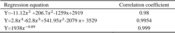
TABLE VI
REGRESSION EQUATIONS FOR ESTIMATING POWER DEMAND IN MILLING
Regression equation Correlation coefficient
Y=-11.12 +206.7 -1259x+2919 0.98
Y=2.8 -62.8 +541.95 -2079 + 3529 0.9954
Y=1938 . 0.999
In studied operations in this case study, the second derivative, don’t have any acceptable roots. Considering hidden inherited error in all regression equations and neglect able difference in correlation coefficients of forth and power equations, forth degree equations are analyzed too.
Equations (4) and (5) are the second degree derivative of forth degree regression equations for estimating power demand in turning and milling operations respectively.
0.000024x 0.0318 1.094 0 (4) Y 33.6x 376.8 1083.9 0 (5) Since these equations do not have any acceptable roots, ensure that increasing MRR never increases MTEC in these specific operations.
Step5. Calculating the roots of the first derivative equation of
the selected equation in step3. Generally the roots of the first derivative equation of a function represent the stop point of ascending or descending tends in that function (the stop point for positive or negative slope). In this case, the root represents a value for MRR, which slight increment in MRR won’t decrease the energy consumption.
0.00008 0, 0159 1.094 26.802 0 (6) 11.2 188.4 1083.9 2079 0 (7) In turning case, the first derivative equation does not have an acceptable root which means increasing MRR always reduces MTEC in the cutting state. In milling, (7) has as an acceptable root which is 4.44 / . This means by increasing MRR to the next possible value, MTEC may remain constant.
Utilizing general proposed models (2) and (3), for estimating MTEC, integrated with proposed methodology, can greatly help process planner to acquire a deep understanding of machine consumption profile in cutting states with respect to cutting parameters. This not only enables estimation of MTEC, but also provides a comprehensive sight of the MTEC profile with its critical cutting parameters in a specific machining operation.
International Journal of Mechanical, Aerospace, Industrial and Mechatronics Engineering Vol:8 No:6, 2014
VI. CASE STUDY
Cutting parameters influence some process specifications such as tool life which can affect machine utilization and alter total energy consumption in idle state. While this interaction is overlooked in current research so far, the tool life contribution on MTEC is analyzed in this research section.
Reviewing carried out researches in tool life and comparing the results illustrates the tremendous negative impact of increasing spindle speed on tool life [3], [7], [12].
Increment in spindle speed leads to reduction in tool life, this equivalently boosts tool replacement actions which in turn may affect machine energy consumption in various ways. In case of manual tool changing, since machine is in standby state, fix energy consumption increases, whereas in automatic changing, variable energy increases. Accordingly, increasing the speed of the spindle may bring some tradeoffs in system dynamic perspective. We analyze these interactions deeply in this section.
On the other hand, selecting each cutting parameter narrows down selection range of other cutting parameters. Considering the same effect of all the mentioned cutting parameters on MTEC, their different effects on tool life, determine the best selection order for them. Since the effect of cutting depth and feed is not noticeable on tool life, they should be parameterized with the maximum value initially. However, spindle speed should be set at the end of the selection process, but the approach regarding giving high or low values is analyzed and determined in this section.
A model based case study is performed to illustrate the approach and do analysis. The production line in case study, aims to produce 3 product variants. In the first station, a robot loads part to lathe and unloads them to the next conveyor. In the next station, the second robot loads parts to an idle milling machine (2 machines in second station) and unloads the final products to the next conveyor, which navigates them to storage. Cutting time, setup and cutting tool differ for each variant.
Taylor equation (8) was used to calculate tool life in machining operations. denotes cutting speed, T represents tool life, D indicates cutting depth, S is feed rate, x and y are determined experimentally. C and n are constants which are selected with respect to tool and work piece material in this case study [9], [10].
In this paper, tool life refers to the number of operations with the same tool, which is calculated by dividing tool life time to cutting time [10].
V T D S C (8)
A. Model Configuration
The model holds several subsystems which maps required properties of the described production line. To avoid the prolixity only the relevant sections are described.
The model interface enables setting the cutting parameters for turning and milling operations. Accordingly, it calculates and sends machining time, material removal rate and tool life to the other related subsystems.
Items (representing parts) get service from turning station subsystem if both machine and robot are idle, and setup conditions are satisfied. Moreover, tool replacement is required in case that tool life has ended. State flow charts and logical operators check these conditions satisfactions.
Blocks and subsystems representing different actions (e.g. loading, unloading and machining actions) broadcast several signals about their states with an energy flowchart which includes two main states; busy and idle. Fig. 3 shows a brief presentation of states relations in energy flowchart. As soon as an item enters to machining subsystem, the chart transits from idle to busy state and calculates consumption in idle state by multiplying idle time and consumption rate in idle state.
Fig. 3 Turning station flowchart; brief representation of state relation Machine operational cycle consists of several states (e.g. clamping, rapid move of tool to part vicinity, spindle acceleration, air cutting, metal cutting), and each has its own power demand profile. Since changes of the cutting parameters only affect metal cutting state, a certain constant consumption is considered for each state excluding cutting state. We utilized (4) for calculating consumption in cutting state, which changes with different given cutting parameters. As soon as an item enters to each state related subsystem, a state signal is sent to the energy flowchart. This triggers activation of related state in energy flow chart. Activation of each state accumulates the relevant energy value to the assigned variable for machine energy consumption in the busy state. Flow chart transits to idle state as soon as the item is released from machining subsystem.
Failure modes and repair times with particular probability
distributions are considered in the model to increase outputs reliability. In case of failure occurrence, the chart activates fail state and transits to idle state as soon as repair time elapsed. Milling station: Main structure and energy state flow of milling subsystem is similar to turning subsystem.
B. System Dynamic Analysis
Subsidiary effects of production planning and cutting parameters on consumption are investigated in this section by simulating the described model and analyzing the results.
1) Cutting Parameter Effect Analysis
All the three mentioned cutting parameters have the same effect on the MTEC profile in cutting state. As mentioned earlier, spindle speed has the highest contribution on tool life comparing to cutting depth and feed rate. As a result, spindle speed noticeably affect the idle or the changeover states frequency and consequently total consumption of machine tools (this does not affect the profile of consumption in these states, but their occurrence frequency and accumulated consumption in a specific time interval). Therefore, in order to understand the comprehensive influence of spindle speed on consumption, its value is manipulated in different simulations while other parameters are kept constant. Each run of simulation with the given cutting parameters are termed as experiment.
The model with the different given cutting sets simulated for 2 working months. The results are shown in Fig. 4. Turning section compares all those experiments results where highest possible MRR was given to milling operation. Hereupon, all the differences in results, address the effect of changing cutting parameters in turning operation. Respectively, milling section compares the results of those experiments which turning has got highest MRR in all the experiments. In turning related experiments, cutting depth and feed are respectively 2mm and 0.2 mm/rev, and in milling are respectively 2mm and 0.2 mm/rev.
Several indexes are defined to attain more pervasive analysis. Total energy consumption; represents consumed energy in machines in all the states, Machine busy energy
consumption refers to consumption of machines in busy state, Idle energy consumption represents consumption in idle state
during simulation time, Total output reflects total production outputs, Average energy consumption per product is calculated by dividing the total energy consumption to total
output.
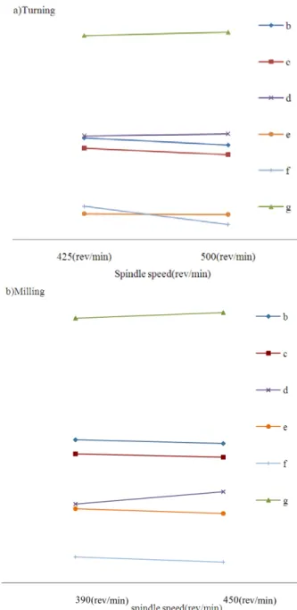
The below conclusions about the effect of spindle speed on busy state consumption are also applicable for other two parameters, since all 3 parameters have the same effect on consumption profile in cutting state.
In both milling and turning sections of Fig. 4, by increasing spindle speed, an obvious reduction pattern in average energy
consumption per product is observed while total idle energy consumption and total output show an increasing tendency. Busy and total energy consumption show slight reduction
trend by increasing spindle speed.
Fig. 4 Spindle speed effect on energy consumption indexes. In turning section; b is total energy consumption in machines, c: total
energy consumption in busy state of machines, d: total output, e: average energy consumption, f: tool life in turning, g: total energy consumption of machines in idle state. In Milling beside f which is
tool life for milling, the rest are the same as turning
Tool life reduction causes more new tool replacement actions, which increases machine idle times, and justifies increment in total idle consumption. Existing trends in the indexes in Fig. 4, clarify that, even increasing spindle speed and consequently tool life reduction, eventuates in increment in idle consumption, but its positive effect on consumption reduction in cutting state, reduces total consumption in busy state. Since consumption during the cutting state is the
dominant part in total consumption, reduction in this state will
reduce total and average energy consumption per product by increasing spindle speed. Total output increment also International Journal of Mechanical, Aerospace, Industrial and Mechatronics Engineering Vol:8 No:6, 2014
aggregates positive effect of increasing spindle speed on reducing average consumption per product. So in conclusion,
spindle speed should be valued high to benefit on total consumption reduction.
Generally, increasing spindle speed or other cutting parameters reduces machining time, which increases total outputs. More outputs need more loading and unloading actions. This increases machine standby frequency which also justifies increment in the total idle energy consumption.
On the other hand, more output increases the number of machining operations which may increase total busy energy consumption, but Fig. 4 shows a slight reduction on it. Increasing cutting parameter values reduces cutting state consumption for each part. As a result, even cutting parameter increment boosts machining operations number, but its positive reducing effect on MTEC in the cutting state is so significant which in turn causes reduction in total consumption of cutting state in mass production as well.
The case study here was a balanced production line, so the results may differ in case of bottleneck and different utilizations of machines in production system. Modeling and simulating integrated with proposed equations; enables process planners to find the best cutting sets for various operations existing in the system. This increases system energy efficiency with respect to each production line specification.
If the production system aims to produce as much as possible, the average energy consumption per product criterion greatly helps to select the best cutting parameters but if it has planned to produce a specific amount of product, total energy consumption should be considered too.
2) Production Planning Effect Analysis
This research section opens a window in the topic of the production planning effect on energy efficiency, by analyzing batch mode production influence on machine energy consumption.
The described model adjusted to batch mode production requirements. In each batch the items variants are the same. It is assumed that all machine setup, fixture adjustment and tool changing actions are performed manually, so the machine is in idle state during these actions which are termed generally
setup actions.
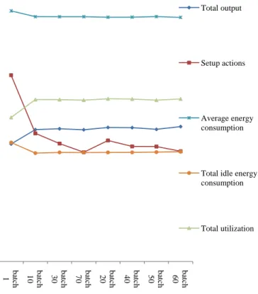
Since batch mode production does not affect machining process, so target index here is the total consumption of machine in idle state. The tuned model has been simulated for 2 working months with the same given cutting parameters but different batch size in each simulation run. The results of the experiments are demonstrated in Fig. 5.
In Fig. 5, an impressive reduction in the average energy consumption is illustrated by increasing batch size from 1 to 10. Batch mode production reduces set up actions due to variant difference. This increases machine utilization which accordingly eventuates in increment in total output and reduction in machine idle consumption. Increment in total output and reduction in idle state consumption, while consumption profile in cutting state is the same, reduces
average consumption per product by increasing the batch size.
Fig. 5 Batch size effect on energy consumption
As shown in Fig. 5, there is an impressive improvement in all related indexes form ‘batch size 1’ to’ batch size 10’, whereas no noticeable change exists from ‘batch size 10’to other values. So, from energy efficiency point of view, it seems the best batch size is 10, since bigger batch, don’t increase energy efficiency, while increases work in progress.
VII. CONCLUSION
This paper presents applicable models and methodologies helping to find better process planning for cutting parameters selection that accounts energy efficiency. The result and insight from this work can provide a reliable perspective of machine energy consumption related to cutting parameters. State dependency of the consumption profiles helps to monitor power demand of machine tools through the operation, giving the opportunity to adjust cutting parameters in order to achieve electricity load balance in production system. Furthermore this research brings up new research area regarding the effect of production planning on energy efficiency by investigating the effect of batch mode production on consumption. There would be wide variety of effective practices to reduce consumption which is recommended for future research, such as, formulating the effect of tool path on cutting state consumption or buffer size between work stations.
ba tc h 1 batc h 10 ba tc h 30 ba tc h 70 ba tc h 20 ba tc h 40 ba tc h 50 ba tc h 60 Total output Setup actions Average energy consumption
Total idle energy consumption
Total utilization
REFERENCES
[1] Jeffery B.Dahmus, Timothy G.Gutowski. Anhaeim, “An Environmental Analysis of Machining,”. ASME International Mechanical Engineering Congress and RD&D Expo, 2004.
[2] Wen Li, Andre Zein, Sami Kara, Christoph Herrmann, “An Investigation into Fixed Energy Consumption of Machine Tools,” 18th CRIP
International conference on Life Cycle Engineering Technische Universität Braunschewig, Braunschewig, 2011.
[3] Nancy Diaz, Moneer Helu, Andrew Jarvis, Stefan Tönissen, David Dornfeld, Ralf Schlosser, "Strategies for Minimum Energy Operation for Precision Machining," Laboratory for Manufacturing and Sustainability in UC, Barkely, 2009.
[4] M. Mori, M. Fujishima, Y. Inamasu, Y. Oda, “A study on energy efficiency improvement for machine tools,” CIRP Annals
-Manufacturing Technology, vol. 60, no. 1, 2011.
[5] F.Dragannescu,M. Gheorghe, C.V.Dion “Models of Machine Tool Efficicency and Spesific Consumed Energy”, Materials Processing
Technology 141(1).P9-15.
[6] S.Kara, W. Li., “Unit process energy consumption models for material removal processes,” Manufacturing Technology, vol. 40, no. 1, P. 37-40, 2011.
[7] M.F. Rajemi, P.T. Mativenga, A. Aramcharoen, “Sustainable machining: selection of optimum turning conditions based on minimum energy considerations,” Cleaner production, vol. 18, no. 10-11, 2010.
[8] Yan He, Fei Liu1, Tao Wu, F. P Zhong, B. Peng, “Analysis and Estimation of Energy Consumption for Numerical Control,” Proceeding
of the Instituation of Mechanical Engineers, Part BJournal of Mechanical of Engineering Manufacture, P. 255-266, 2012.
[9] M.Alauddin, M.A. El Baradie, M.S.J. Hashmi, “”Prediction of tool life in end milling by response surafce methodology,” Material Processing
Technology, vol. 71, no. 3, P. 456-465, 1997.
[10] D.K. Ojha, U.S.Dixit, “an economic and reliable tool life estimation procedure for turning,” Advance Manufacuring Technology, P. 726-732, 2005.
[11] WANG Ting, ZHANG Shiqiang, "Study on Linear Correlation Coecient and Nonlinear Correlation Coecient in Mathematical Statistics," Studies
in Mathematical Sciences, vol. 3, P. 58-63, 2011
[12] DuraiMatinsuresh Babu, Mouleeswaran Senthil Kumar, Jothiprakash Vishnuu., "Optimization of Cutting Parameters for CNC Turned Parts Using Taguchi’s Technique," International journal of engineering, no. FASCICULE3(ISSN1584-2673), 2012.
International Journal of Mechanical, Aerospace, Industrial and Mechatronics Engineering Vol:8 No:6, 2014
International Science Index Vol:8, No:6, 2014 waset.org/Publication/9998612