SKI Report 96:77
Common Cause Failure Analysis of
Hydraulic Scram and Control Rod Systems
in the Swedish and Finnish BWR Plants
Tuomas Mankamo
December 1996
ISSN 1104-1374 ISRN SKI-R--96/77--SE
SKI Report 96:77
Common Cause Failure Analysis of
Hydraulic Scram and Control Rod Systems
in the Swedish and Finnish BWR Plants
Tuomas Mankamo
Avaplan Oy
Itainen rantatie 17, FIN-02230 Espoo
Finland
December 1996
Avaplan Oy Document ID: SKI-CCF-RS\Doc\RS-SummR.doc
This report concerns a study which has been conducted for the Swedish Nuclear Power Inspectorate (SKI). The conclusions and viewpoints presented in the report are those of the
Summary
The hydraulic scram and control rod systems of a Boiling Water Reactor (BWR)
represent ultra-highly redundant systems. In the current Probabilistic Safety Assessment
(PSA) studies, these systems are quantified in a crude way and by using engineering
judgment, which means significant uncertainties.
This project continues the earlier work done in the analysis of the safety/relief valve systems, which served as a basic development for the Common Cause Failure (CCF) analysis of highly redundant systems.
The main tasks of the project included the analysis of the operating experiences at the BWRs of ABB Atom design, comprising 9 units in Sweden and TVO I/II in Finland. Also international experience and reference information were surveyed. A reference application was done for the Barsebäck 1/2 plant. This pilot study covered all systems which contribute to the reactor shutdown, including also the actuation relays at the interface to reactor protection system. The Common Load Model was used as the quantification method, which proved to be a practicable approach. This method provides a consistent handling of failure combinatorics and workable extension to evaluate localized dependence between adjacent control rod and drive assemblies (CRDAs). As part of this project, instructions of handbook style were prepared for the CCF analysis of high redundancy systems. The instructions give step-wise description of the procedures for data analysis, quantification of CCFs and integration of off-line calculations with the PSA framework.
The primary focus in the analysis of operating experience was placed on the scram valves and CRDAs. In this task evolved a new logical scheme to classify interconnected failure modes of the two redundant functions of the CRDAs:
• fast hydraulic insertion and • slower screw drive function
The developed classification frame makes an explicit distinction between the different attributes of the failure event:
• affected function • movement direction • detectability
• criticality, i.e. inoperable versus only degraded component state
A novel idea emerged for grouping the events according to generic failure mechanism. The generic classes will help to organize and structure the information very effectively, because in most cases within a class, the failure modes prove to be same, or there are only a few alternatives to chose from.
Due to the limited component population, the experiences for the scram valves constitute only a few single failures and some potential but none actual CCF events. These insights are compatible with the generic data for these valves.
The experiences for the CRDAs include several single failures, and some actual and many potential CCF events of varying degree of functional impact. Special emphasis was placed to identify any multiple failure or degradation indicating that adjacent rods would be more vulnerable to failure, because such phenomena are far more critical for the scram function as compared to failure of randomly placed rods. Only slight
tendency of position correlation could be determined. Another positive insight was that the events, where foreign objects caused the failure of rod insertion, were separated by both substantial time difference and/or spatial distance within the core.
Regarding the quantitative results of the reference application, the estimated failure probability per demand, due to high order CCF of CRDAs, ranges from
• about 1E-4 for only the screw drive function to
• about 1E-6 for both the hydraulic insertion and screw drive function failing The developed methods and collected data are utilized in the ongoing PSA updates for the Swedish BWRs and TVO I/II. The collected data will also form a contribution to the International CCF Data Exchange (ICDE).
Sammanfattning
Det hydrauliska snabbstoppsystemet (system 354) och systemen för drivdon/styrstavar (221/222) i kokvattenreaktorer (BWR) representerar s k högredundanta system.
I nuvarande Probabilistic Safety Assesment (PSA) studier behandlas dessa system på ett relativt grovt sätt. Ingenjörmässiga bedömningar har använts till stora delar i dessa analyser och detta innebär att stora osäkerheter råder i dessa studier.
Detta projekt är en direkt fortsättning på de tidigare Common Cause Failure (CCF) analyserna och datasamlingarna för säkerhets- och avblåsningsventiler i system 314 i de svenska och finska BWR anläggningarna.
Projektets huvudsakliga syften har varit att sammanställa och klassificera verkliga och potentiella beroenden utifrån de kända driftserfarenheterna hos ABB Atom BWR anläggningarna, som omfattar 9 reaktorblock i Sverige och TVO I/II i Finland. Även internationella drifterfarenheter har kartlagts i projektet. En pilotstudie har utförts för Barsebäck 1 och 2, var system som bidrar i reaktoravställnings funktionen, inklusive ändreläer med gränssnitt mot reaktorskyddssystemet (516) har analyserats. Som
kvantifieringsmetod har använts den s k Common Load Model. Modellen har visat sig fungera på ett förträffligt och konsekvent sätt vid behandlingen av bl a felkombinato-riken. Metoden har även kunnat utnyttjas för att ta hänsyn till identifierade CCF
mekanismer av närliggande drivdon/styrstavar. En produkt som tagits fram i projektet är en handbok om hur CCF analyser i högredundanta system kan utföras. Instruktionerna i handboken beskriver i steg för steg, t ex hur man kan genomför själva
datainsamlingen, kvantifieringen av CCF och integrationen av externa beräkningar m h a PSA.
En detaljerad analys av drifterfarenheterna riktades på snabbstoppsventiler och drivdon/styrstavar, vilka prioriterades i pilotarbetet för Barsebäck 1 och 2. En ny klassificeringstruktur utvecklades som tar hänsyn till de två diversifierade funktionerna för reaktoravställningen, nämligen:
• den snabba hydrauliska inskjutningen av styrstavar • den långsammare elektriska inskruvningen av styrstavar.
Klassningen som utförts skiljer på väsentliga egenskaper i felhändelserna: • förhindrad eller degraderad funktion
• rörelseriktning
• möjlighet att upptäcka felet
• felets kriticitet, d v s funktionshindrande alt ej funktionshindrande I pilotarbetet har händelserna grupperats i s k generiska felmekanismer, för att möjliggöra en effektiv hantering av händelseinformationen.
Det begränsade antalet komponenter och driftår på snabbstoppsventilerna har resulterat att vi i den genomförda CCF analysen har endast kunnat identifiera ett fåtal enkelfel och ett fåtal potentiella CCF händelser på dessa ventiler.
Driftserfarenheterna på drivdon/styrstavar uppvisar flertalet enkelfel samt ett större antal potentiella CCF händelser av olika funktionell betydelse. Stor vikt har lagts ner på att identifiera multipla fel av intilliggande drivdon/styrstavar. Fel av denna typ är mycket mera kritiska för funktionen - utebliven reaktoravställning än slumpmässigt inträffade fel i härdgeometrin. I analysen kunde vi inte identifiera några starka tendenser för denna typ av fel. En annan intressant iaktagelse var för händelser, där främmande föremål förhindrat inskjutning eller inskruvning, att dessa uppvisade en stor spridning vad avser tidpunkter för inträffandet och vilka härdpositioner som berörs. Kvantitativa resultat från pilotstudien har givit följande sannolikheter p g a CCF i drivdon/styrstavar med hög multiplicitet:
• cirka 1E-4 för utebliven inskruvning
• cirka 1E-6 för samtidig utebliven inskruvning och hydraulisk inskjutning Den utvecklade metodiken och datainsamlingen används idag i pågående PSA
updateringar vid de svenska BWR anläggningarna samt vid TVO I/II. Datainsamlingen som utförts i detta projekt kommer att på ett direkt sätt gagna CCF data insamlingen inom det nu pågående och aktuella internationella ICDE-projektet.
Acknowledgments
The author will thank the Swedish Nuclear Power Inspectorate (SKI) for the principal funding of the project and support to the development work. Special thanks are due to Lennart Carlsson, the project supervisor, and Ralph Nyman who extracted the Swedish events from the STAGBAS and provided valuable help in gathering further information. The author will also thank the Finnish Centre for Radiation and Nuclear Safety (STUK) and Teollisuuden Voima Oy (TVO power company) for co-funding the project. Thanks are due to Reino Virolainen and his collaborators at the STUK, specially for providing access to the NEA/IRS data base for international events. At the TVO Jari Pesonen, Raimo Nieminen and Pekka Nousiainen provided technical information and many useful comments which promoted to the development of the failure analysis.
Thanks are due to Peter Moriz and Peter Jacobsson at the Sydkraft power company and engineering group, who provided valuable help in accomplishing the reference
application for Barsebäck 1/2.
Finally, Anders Forss at the Vattenfall Energisystem AB and Sven Ordeus at the Forsmarks Kraftgrupp AB are thanked for the help in gathering information for the events at the Forsmark and Ringhals plants.
Notice
This project is conducted within the research program of the Swedish Nuclear Power Inspectorate (SKI), under Contract Nr. 92339/13.5.2-920403. The project is co-supported by the Finnish Centre for Radiation and Nuclear Safety (STUK), the Swedish nuclear power companies and the Finnish Teollisuuden Voima Oy (TVO).
Table of Contents
Summary i Sammanfattning iii Acknowledgements v Notice v 1 Project Outline...1 1.1 Background 11.2 Reactor shutdown systems and failure criteria issue 1
1.3 Special aims and scope of the project 3
1.4 Project documentation 4
2 Survey of the Swedish and TVO I/II Experience ...5
2.1 Survey of the information bases 5
2.2 Scram Valves 6
2.3 Failure Modes of CRDAs 9
2.4 Qualitative Insights per CRDAs 14
2.5 Quantitative Insights per CRDAs 18
3 Comparison and Application of CCF Models...21
3.1 Handling Combinatorics 21
3.2 Ultra-Highly Redundant Systems 22
3.3 Localized CCF Mechanisms 24
3.4 Discussion of other approaches 26
3.5 Instructions for CCF analysis of highly redundant systems 28
4 Reference Application to Barsebäck 1/2...29
4.1 Overview of RS systems 29
4.2 Failure paths 30
4.3 CCF quantification of RS actuation relays 30
4.4 CCF quantification of hydraulic scram system 30 4.5 CCF quantification of control rods and drives 31 4.6 Combined failure probability of RS function 32
5 Review of World-Wide BWR Experience ...34
5.1 International Operating Experience 34
5.2 Comparison of PRA Data 34
6 Conclusions and Recommendations ...36 References ...37 Acronyms and abbreviations...38
1 Project
Outline
This project is conducted within the research program of the Swedish Nuclear Power Inspectorate (SKI), aimed to develop the methods and data base for the Common Cause Failure (CCF) analysis of highly redundant reactor scram systems. The project is co-supported by the Finnish Centre for Radiation and Nuclear Safety (STUK), and the Swedish nuclear power companies and the Finnish Teollisuuden Voima Oy (TVO).
1.1 Background
This project is continuation to the work done in the CCF analysis of the safety/relief valve systems [HRed_FRX], which served as basic development for the CCF analysis of highly redundant systems. For an ultra-highly redundant system represented by the control rod and drive system, the early development done within TVO I/II PSA was utilized as a starting point [TVO/PSA-89].
In the current PSA studies, these systems are quantified mostly in a crude way and by using engineering judgment, which means significant uncertainties.
The current project phase is aimed at a survey of existing data bases for the main components of the BWR hydraulic scram and control rod systems, and at a reference application for the Swedish BWR plant Barsebäck 1/2. This phase should serve planning and focusing of efforts for the more detailed data analysis and thorough qualitative analysis of the CCF mechanisms in an optional continuation phase. In the future, the developed methods may be extended to applications for the PWR shutdown systems.
1.2 Reactor shutdown systems and failure criteria issue
By reactor shutdown (RS) system is meant in this context the systems (of a BWR plant) which are used to
a. accomplish a prompt transition to subcritical condition by hydraulic insertion of control rods into the reactor core (so called hydraulic scram)
b. shut down the reactor in a smooth way by inserting control rods by motor drives (so called screw insertion)
c. trip reactor coolant pumps (RCPs) which facilitates both rapid transition to and retaining the subcritical condition in the shutdown state
d. complete the transition and secure subcritical state in longer term by boron injection
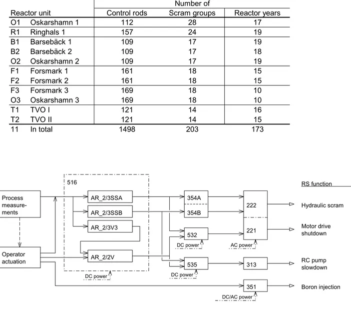
The RS systems and there principal connections are schematically presented in Fig.1.1 for Barsebäck 1/2.
Table 1.1 General population information for the reactor shutdown systems of the Swedish and Finnish BWR plants.
Number of
Reactor unit Control rods Scram groups Reactor years
O1 Oskarshamn 1 112 28 17 R1 Ringhals 1 157 24 19 B1 Barsebäck 1 109 17 19 B2 Barsebäck 2 109 17 18 O2 Oskarshamn 2 109 17 19 F1 Forsmark 1 161 18 15 F2 Forsmark 2 161 18 15 F3 Forsmark 3 169 18 10 O3 Oskarshamn 3 169 18 10 T1 TVO I 121 14 16 T2 TVO II 121 14 15 11 In total 1498 203 173 AR_2/3SSA AR_2/3SSB AR_2/3V3 AR_2/2V 354A 354B 532 535 313 351 222 221 Process measure-ments Operator actuation 516 AC power Hydraulic scram Motor drive shutdown Boron injection RC pump slowdown RS function DC power DC/AC power DC power DC power
516 Reactor protection system Skyddsystem med anslutande mätsystem AR_2/3SSA Actuation relays, SS signal, group A Utlösningsreläer, SS-villkor, grupp A AR_2/3SSB Actuation relays, SS signal, group B Utlösningsreläer, SS-villkor, grupp B AR_2/3V3 Actuation relays, V3 signal Utlösningsreläer, V3-villkor AR_2/3V Actuation relays, V signal Utlösningsreläer, V-villkor 532 Rod drive control system Manövrering av styrstavar
535 RC pump slowdown control system HC-pumpnedstyrning
221 Control rods Styrstavar
222 Rod drives Drivdon
313 RC pumps HC-pumpar
351 Boron injection system Borsystem
Control rod and drive system is an ultra-highly redundant system with more than one hundred identical, redundant control rod and drive assemblies (CRDAs), compare to Table 1.1.
In many transient cases, the hydraulic insertion and screw insertion are redundant functions. Mechanical jamming of the control rods, which disables both functions, constitutes the most critical failure mode, even though its probability is relatively low. The screw insertion function is more vulnerable to jamming as compared to hydraulic insertion, especially due to slip coupling, which protects equipment for mechanical damage (this local protection is called here as moment trip). The failure mechanisms shared by the two functions may have developed critical for screw insertion while still incipient for hydraulic insertion. Part of the failure mechanisms are specific to screw insertion or hydraulic insertion, but not common to both. This means complicated relationship between the failure modes, which necessitated the development of a new logical structure of failure classification as will be discussed in Chapter 2.
In severe LOCAs and special transients, crediting screw stop is questionable due to its low speed, which means that in those cases the reliability of hydraulic scram system is critical. It is also a highly redundant system, comprising of 14-28 modules at the Swedish BWRs and TVO I/II, compare to Table 1.1.
There use to be six RCPs. Consequently this system belongs also to the category of highly redundant systems.
1.3 Special aims and scope of the project
The most difficult topic is jamming of multiple control rods. The possible failure mechanisms may either affect randomly placed rods or adjacent rods due to a localized mechanism. Considering these with realistic failure criteria (for example, 4 or more adjacent rods, or 25% or more randomly scattered rods failing to insert) challenges the analysis method both with regard to failure dependence modeling and to proper
handling of failure combinations.
In order to learn about the actual failure mechanisms, the operating experiences of Swedish BWRs and TVO I/II were analyzed [RS_SweDB, TV_RSCCe]. Emphasis was placed on a careful evaluation of even noncritical faults and symptoms. In addition, the available information from the international data base NEA/IRS was reviewed, as well as foreign PSA studies [RS_WWExp].
Review of the US data, which had been available in raw form via INPO/NPRDS, was left out from this project phase due to resource limitations (soon available in a
processed form via the international exchange workgroup [ICDE]).
As part of this project, instructions of handbook style were prepared for the CCF analysis of high redundancy systems, in order to enhance wider implementation of the
methods [CA_HRedI]. The instructions contain more detailed descriptions of the procedures for data analysis, quantification of CCFs and integration with the PSA framework.
1.4 Project documentation
In addition to this summary report, work documentation is collected as work reports in a folder, being indexed as SKI/RA-26/96. Copies of this material are archived at SKI, STUK and TVO, and will be submitted on request. The folder contains the following work reports, denoted here by reference acronyms:
RS_PPlan CCF analysis of BWR hydraulic scram and control rod systems. Project plan prepared by T. Mankamo, Avaplan Oy, 18 October 1991.
CA_HRedI Instructions for CCF analysis of high redundancy systems. 2nd Version, T. Mankamo, Avaplan Oy, 22 November 1995.
CLM_LocZ Application of Common Load Model to localized CCF mechanisms of control rods. Work notes, T. Mankamo, Avaplan Oy, 15 April 1994. RS_WWExp World-wide BWR experience on CCFs affecting reactor scram function.
Work report, T. Mankamo, Avaplan Oy, 30 November 1996.
RS_BRAwr Barsebäck reference application. SKI/CCF Analysis of BWR reactor shutdown systems, Work report prepared by T. Mankamo, Avaplan Oy, 12 April 1994.
TV_RSCCE CCF analysis of BWR reactor shutdown systems, based on the operating experience at the TVO I/II in 1981-1993. Prepared by T. Mankamo, Avaplan Oy, for the Finnish Centre for Radiation and Nuclear Safety, Report STUK-YTO-TR 100, April 1996.
RS_SweDB BWR/Reactor shutdown systems, CCF data base, Swedish experience 1983-1995. Work report, T. Mankamo, Avaplan Oy, 30 December 1996. CR_RO22x Sammanställning av kommentarer vid RO-analys för drivdon/styrstavar
(BWR). Anmärkningar, Avaplan Oy, 1996-12-30.
T-BokenR T-Bokens data om drivdon/styrstavar (BWR). Anmärkningar, Avaplan Oy, 1996-12-30.
The last two work notes collect open items regarding the event analysis for the Swedish BWR plants; the scope of this work did not contain ordinary review of the event
classification by the plant staff. Only the data analysis for the TVO I/II is qualified in that meaning (referred to as [TV_RSCCE], published by the Finnish Centre for Radiation and Nuclear Safety, as Report STUK-YTO-TR 100).
2 Survey of the Swedish and TVO I/II Experience
Primary emphasis was placed in the analysis of the experiences at the BWRs of ABB Atom design. Similar approach as in the data analysis for safety/relief valves was
applied [HRed_FRX]. Components to be covered in the data analysis were decided after a preliminary survey of operating experience information from different sources. The general population information over the event analysis period is summarized in Table 2.1.
2.1 Survey of the information bases
The survey was started, using information from the PRA studies, with identification of the most critical components contributing to the reliability of reactor shutdown systems in the BWR plants of ABB Atom design; these systems include control rod and drive system, hydraulic scram system, RCP slowdown and boron injection system, as well as the associated actuation, control and instrumentation systems, and interfacing systems.
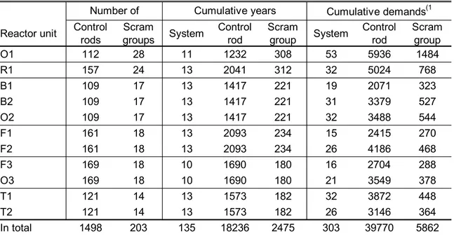
Table 2.1 Population information over the event analysis period Swedish BWRs: 1983-95
TVO I/II: 1981-93.
The demands include only actual reactor scrams, i.e. not periodic tests or other test demands.
Number of Cumulative years Cumulative demands(1
Reactor unit Control rods groupsScram System Control rod Scram group System Control rod Scram group
O1 112 28 11 1232 308 53 5936 1484 R1 157 24 13 2041 312 32 5024 768 B1 109 17 13 1417 221 19 2071 323 B2 109 17 13 1417 221 31 3379 527 O2 109 17 13 1417 221 32 3488 544 F1 161 18 13 2093 234 15 2415 270 F2 161 18 13 2093 234 26 4186 468 F3 169 18 10 1690 180 16 2704 288 O3 169 18 10 1690 180 21 3549 378 T1 121 14 13 1573 182 32 3872 448 T2 121 14 13 1573 182 26 3146 364 In total 1498 203 135 18236 2475 303 39770 5862
Information sources for the operating experience and reliability data were then surveyed covering:
- RO event base (Swedish LERs)
- reliability data base of the Swedish & TVO nuclear power plants (ATV system) - NEA/IRS data bank
- INPO/LER information
- component reliability data and CCF analyses by EPRI and USNRC - PRA studies
The more detailed analysis of the Swedish and TVO experience was focused on control rod and drive assemblies (CRDAs) and scram valves. The event analysis was first undertaken for the TVO I/II, covering years 1981-93 [TV_RSCCE]. During this stage evolved a new way to classify failure modes for CRDAs, to be described in Section 2.3. The interpretation of the events at the TVO I/II was done in co-operation with the plant staff.
In the next stage, the developed procedure was followed to analyze the much larger amount of events at the Swedish BWRs [RS_SweDB]. Because of the limited resources, no systematic verification by the plant personnel could be incorporated for the Swedish events, except a few selected cases of special importance. For the bulk of the events, interpretation and classification were done by the author based only on what is told in the RO-reports. Most important open questions and discrepancies found in comparison with the component data base [T-book 4] are collected into separate work notes
[CR_RO22x, T-BokenR], waiting for optional continuation with a more thorough event analysis.
The survey of the international information will be discussed in Chapter 5.
2.2 Scram Valves
The BWR units are equipped with varying number of hydraulic scram lines. Six to eight control rods, called as scram group, are driven by each hydraulic scram line.
The most important valves in the hydraulic scram line are the following:
• scram valves, which are air operated valves, normally closed; these valves are opened to execute hydraulic scram by using the high pressure from the scram tank, and reclosed after scram
• external isolation valves, which are also air operated valves, normally open; they are spring-forced open in case of loss of power or air supply; these valves are closed after scram
After the internal isolation valves the line is divided up into injection branches connected to the CRDAs in the scram group. At the inlet to the CRDA, there is so called drive check valve, which is considered as part of the CRDA.
Other components in the line are not handled separately, because most of their failure modes are self-revealing, while latent critical failure modes are unlikely. The monitored critical failure modes are designed to lead into automatic partial scram. The monitored non-critical failure modes cause repair unavailability of the hydraulic scram line (in power operation state within AOT), and mean decreased system redundancy, which is specifically taken into account in PRA models. The majority of the events affecting these other components are vent line leakage, other shortly detectable external or internal leakage, or alarms on the low level in the scram tanks.
The event base contained three actual failures of the external isolation valves, in mode failure to close. Two of the events were intra-line CCFs between external isolation valve and scram valve as will discussed in more detail in Section 2.2.2. The noncritical events include one potential CCF mechanism which affected all 14 valves at TVO I in 1986. The weld cracking in the actuator component can be considered as a potential degradation with respect to valve closure. Most of the events reported for the external isolation valves are concerned with internal leakage, which seem to be randomly scattered over time and redundant components, being mostly detected in the annual overhaul tests.
The events reported for the isolation check valves included one old event from TVO I in 1981, being classified as failure to reclose. Other events are mostly randomly scattered internal leaks.
The scram valves are tested monthly (a movement test). Scram tests are carried out when shutting down to and again when starting up from the annual overhaul outage. Most part of reported events are monitored noncritical failures, such as shortly
detectable air leaks. There are reported four critical failures, which will be discussed in the following subsections.
2.2.1 Scram Valves, Failure to Open
There is only one reported event where the scram valve failed to open. This occurred in Oskarshamn 2 in 1989, when scram valve V407 failed to open in periodic test. The top seal of the indicator pin was made with araldite (a two-component glue). This had loosened and clogged the relief hole for the pilot disc. Two months later, a slow leakage from scram valve 354 V406 was detected during an inspection tour. Air leakage was through pilot disc. A small mark was noticed in the valve seat. This mark derived from araldite which had come loose from the indicator pin. The valve was replaced with spare valve with new indicator pin design. The replacement action was told to be scheduled for all scram valves during the refueling outage in 1989 at the Oskarshamn 2. The above history involves a CCF mechanism which can be considered as one critical failure and one degraded state of the redundant component.
As the data base contains about 2475 component years for scram valves (compare to Table 2.1), we obtain the following point estimate for the failure to open (FO)
λFO
h
= 1 =
2475 8760* 4.6E - 8 / h (2.1)
This is significantly smaller than the generic data for air operated valves. The test interval of one month leads to the estimate for mean unavailability of 1.7E-5. No actual CCFs could be expected due to small data base.
2.2.2 Scram Valves, Failure to Reclose
One of the three actual failures of the external isolation valves, in mode failure to close, can be considered a random component failure, while the other two events deserve special attention, being discussed below. The failure to reclose is critical in order to prevent interfacing system LOCA.
Scram valve VD4 failed to reclose at Forsmark 3 in connection to reactor trip, in 1986, because actuation from low level in scram tank malfunctioned. The scram function for the group was successful. The cause was a latent defect in signal converter. As a result external isolation valve VD24 did not close either. A similar event affecting VD3 and VD23 occurred again in Forsmark 3, in 1994. These two intra-line CCF events (CCF of two series connected isolation valves) are particularly important, because only the internal isolation valve (check valve) was left in the affected lines.
2.2.3 Pilot Valve Defects
Scram valves are actuated by four magnet valves connected as 2/4 logic. A problem with a single magnet valve is hence not critical. The magnet valves were affected by a potential CCF mechanism in autumn 1992 at the TVO I/II, including four events at Unit I and three at Unit II. The events were distributed over separate test cycles. In the preceeding annual overhaul 1992, new magnet valves had been installed; the grease inside the valve caused jamming in the operating conditions; two from each group of four magnet valves were replaced in the following annual overhaul 1993. There are reported a few events at the Swedish BWR units concerned with the pilot valves, but no problems similar to those at the TVO I/II in 1992.
2.3 Failure Modes of CRDAs
2.3.1 Component boundary
A schematic diagram of the control rod and drive is presented in Fig.2.1. The concerned components belong to the following plant systems:
• control rod (system number 222)
• control rod drive including the electric motor and the mechanical accessories (system number 221)
• control equipment of motor drives (system number 532)
• instrumentation and mechanical equipment for position indication (system number 533)
It is impossible to make a workable physical division of the components related to hydraulic and motor drive functions. Generally, hydraulic function is stronger against jamming mechanisms, i.e. developing problems usually first affect motor drive function, and are then removed or taken under control. But the functions are much interconnected and share some failure mechanisms. Consequently, no internal division of the
components was implemented. Instead, the control rod and drive assembly (CRDA) is handled as a functional unit with multiple failure modes, physically comprising the components belonging to the four above mentioned systems (221/222/532/533). The boundary definition excludes the actuation relays which provide shutdown command from the reactor protection system (516), components in hydraulic scram system (354) up to internal isolation valve, and power buses.
Movement tests (2% up-down movement by the screw) are done biweekly in order to detect any jamming problem already at incipient status. Scram tests are carried out when shutting down to and again when starting up from the annual overhaul outage.
2.3.2 Position correlation
The failure of the adjacent rods to insert in reactor scram is far more critical as
compared to randomly placed rods. Depending on the plant, from three to five adjacent rods failing is considered critical, while only about 25% percent or more of randomly placed rods failing is likely not to anymore guarantee transition to stable subcritical state. Special emphasis was thus directed to identify any multiple failure or degradation indicating that adjacent rods would be more vulnerable to failure. The failure
mechanisms affecting adjacent rods fall into the following types:
• radially scattered: one CRDA is first affected and the failure mechanism then successively “escalates” to neighboring CRDAs
• band correlated: the necessary physical or other conditions for failure are confined at a specific distance from the core centre
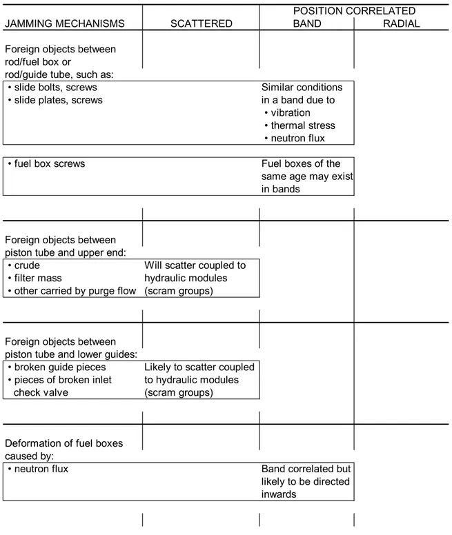
Possible failure mechanisms of these types are collected into Table 2.2. The efficient preventive measures against position correlation include movement of the fuel elements within the core during refueling, which partially follows a random pattern, as well as the design selection of how the control rods are placed into the scram groups.
Table 2.2 Failure mechanisms for control rods and drives resulting in jamming, classification with regard to position correlation.
POSITION CORRELATED JAMMING MECHANISMS SCATTERED BAND RADIAL Foreign objects between
rod/fuel box or
rod/guide tube, such as:
• slide bolts, screws Similar conditions • slide plates, screws in a band due to
• vibration • thermal stress • neutron flux • fuel box screws Fuel boxes of the
same age may exist in bands
Foreign objects between piston tube and upper end:
• crude Will scatter coupled to • filter mass hydraulic modules • other carried by purge flow (scram groups)
Foreign objects between piston tube and lower guides:
• broken guide pieces Likely to scatter coupled • pieces of broken inlet to hydraulic modules check valve (scram groups)
Deformation of fuel boxes caused by:
• neutron flux Band correlated but likely to be directed inwards
2.3.3 Classification approach
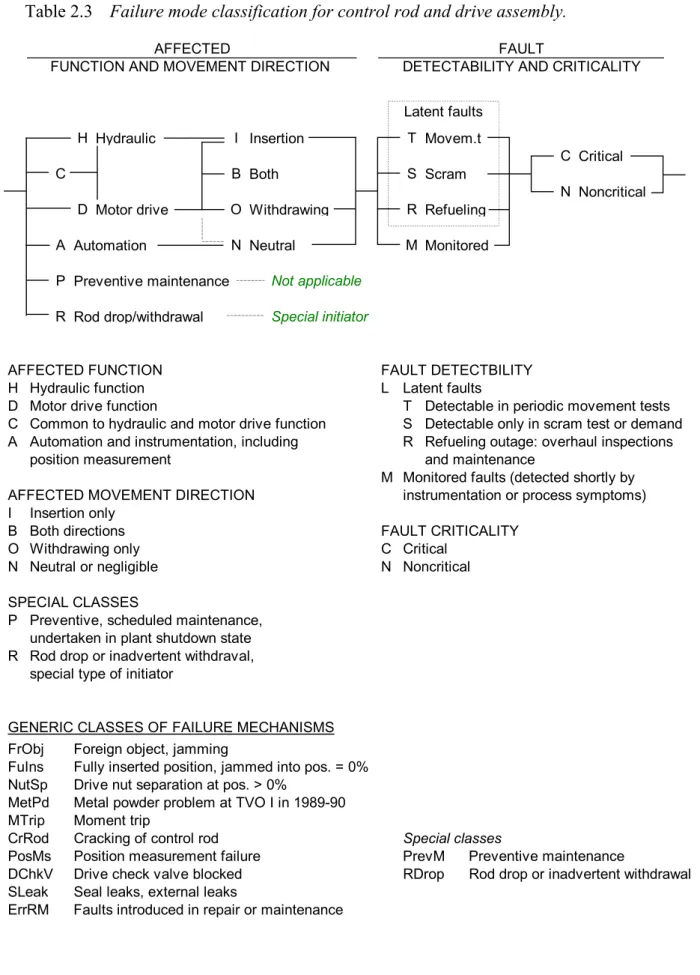
Because of the interconnections between the failure mechanisms affecting hydraulic insertion and motor drive function, a special logical frame was developed to consider the both functions in parallel, Table 2.3. This feature represents a new methodological approach developed in this study. The classification frame makes an explicit distinction between the different attributes of the event (actual or potential failure):
• affected safety function • affected movement direction • detectability
• criticality
The logical scheme in Table 2.3 shows principal relationships between various attributes. What is not shown is the rule to classify all events, in which the rod withdrawal only fails, as noncritical.
2.3.4 Generic failure mechanisms
The pioneering work with the TVO I/II data showed, that it is best to start with grouping of the events according to generic failure mechanisms [TV_RSCCe]. These are defined in the lower part of Table 2.3 representing another new methodological approach developed in this study. The generic classes will help to organize and structure the information very effectively, because in most cases within a class, the failure modes prove to be same, or there are only a few alternatives to chose from. About 10% of cases remain as miscellaneous, nongeneric type. Most of these “nonclassified” events are noncritical events.
Special emphasis was placed on the failure mechanisms which are - directly or
potentially - related to jamming: these include FrObj, FuIns, NutSp, MetPd (a specific problem which affected TVO I in 1989-90), MTrip and CrRod classes.
Failures of the position indication, generic class PosMs, have generally no direct influence on the reactor scram function. They are then classified as failure mode AN.*N. Most failures of position indication are recorded onto system 533, but not systematically. Some events which are related to mechanical devices for position indication may have been coded onto system 221.
The failure class of rod drop/inadvertent withdrawal is added for completeness. It represents a different category of failure consequence, being initiating events of transient sequences. Inadvertent withdrawal of control rods by operator error belongs also to this class.
Table 2.3 Failure mode classification for control rod and drive assembly.
AFFECTED FAULT
FUNCTION AND MOVEMENT DIRECTION DETECTABILITY AND CRITICALITY
H I T C C B S N D O R A N M P Not applicable R Special initiator
AFFECTED FUNCTION FAULT DETECTBILITY H Hydraulic function L Latent faults
D Motor drive function T Detectable in periodic movement tests C Common to hydraulic and motor drive function S Detectable only in scram test or demand A Automation and instrumentation, including R Refueling outage: overhaul inspections
position measurement and maintenance
M Monitored faults (detected shortly by AFFECTED MOVEMENT DIRECTION instrumentation or process symptoms) I Insertion only
B Both directions FAULT CRITICALITY O Withdrawing only C Critical
N Neutral or negligible N Noncritical
SPECIAL CLASSES
P Preventive, scheduled maintenance, undertaken in plant shutdown state R Rod drop or inadvertent withdraval,
special type of initiator
GENERIC CLASSES OF FAILURE MECHANISMS FrObj Foreign object, jamming
FuIns Fully inserted position, jammed into pos. = 0% NutSp Drive nut separation at pos. > 0%
MetPd Metal powder problem at TVO I in 1989-90 MTrip Moment trip
CrRod Cracking of control rod Special classes
PosMs Position measurement failure PrevM Preventive maintenance
DChkV Drive check valve blocked RDrop Rod drop or inadvertent withdrawal SLeak Seal leaks, external leaks
ErrRM Faults introduced in repair or maintenance Withdrawing Insertion Motor drive Hydraulic Movem.t Neutral Automation Preventive maintenance Monitored Critical Noncritical Both Rod drop/withdrawal Scram Latent faults Refueling
2.4 Qualitative Insights per CRDAs
The distribution of Generic Classes for BWR units is summarized in Fig.2.2, and the principal observations will be discussed in the following subsections. More compre-hensive summary tables are presented in work reports [TV_RSCCE, RS_SweDB].
2.4.1 Foreign objects (FrObj)
There are nine events where foreign objects caused a critical failure of rod insertion: six affected exclusively the screw function, three exclusively the hydraulic function, and in one event, at Forsmark 3 in 1985, both functions failed. All nine events show time or spatial separation, i.e. no actual CCF. However, rod withdrawal problems caused by foreign objects include CCF histories, which could be investigated further.
GenClass B1 B2 F1 F2 F3 O1 O2 O3 R1 R2 R3 R4 T1 T2 Sum NonCl 11 3 3 4 1 3 4 5 5 6 2 47 FrObj 2 1 13 3 14 4 2 15 9 4 67 FuIns 1 1 1 2 1 6 NutSp 1 5 1 7 MetPd 37 4 41 MTrip 13 15 12 14 18 27 7 6 7 119 CrRod 5 32 7 44 PosMs 13 27 9 12 8 41 58 11 46 11 28 264 DChkV 1 1 2 2 6 SLeak 4 2 6 ErrRM 1 1 3 1 2 1 5 14 PrevM 3 1 4 RDrop 9 1 1 1 12 All 41 46 37 55 16 78 97 20 110 89 48 637 0 10 20 30 40 50 60 70 80 90 100 110 120 B1 B2 F1 F2 F3 O1 O2 O3 R1 R2 R3 R4 T1 T2 Number of events Other MTrip FrObj
2.4.2 Moment trips (MTrip)
There are 99 events where moment trip, i.e. slip coupling or overcurrent protection was part of a critical failure of screw insertion. The prevalent causes are
- high friction in shaft seal/tightening as a result of crud accumulation and/or wearout
- back-leakage impact causing high friction in shaft seal/tightening
- crud caused binding of the drive nut and screw, particularly due to graphite dust - sticking due to castor oil used for lubrication of graphite O-rings
- high inertia/friction at the initial movement phase with respect to desired trip setpoint (eliminated later by trip delaying circuit)
- damaged ball bearings
Moment trips due to foreign objects are classified as FrObj, and metal powder problem at TVO I in 1989-90 are considered as a separate class MetPd.
In many cases the above mechanisms have contributed in combination. In quite many cases, the RO-report does not clearly describe the root causes, especially if they have not been evident by symptoms, but revealed only later when doing corrective
maintenance (often in the next refueling outage).
The events in this class include the following actual CCF events regarding the screw insertion function, based on CCF screening window of 2 weeks in accordance with the interval of periodic movement tests:
• eleven double failure events; two of these cases were separated by three weeks and can thus be considered a potential CCF of order 4 (the cause was back-leakage impact in shaft seal/tightening)
• one event of order 4, where the slip clutch tripped the screw insertion in periodic movement tests (Oskarshamn 2, May 1988); the failures of four CRDAs were distributed within 10 days’ time window; this CCF event is of particular interest because three of the failed CRDAs constituted a L-shape of adjacent rods; the cause was related to the use of castor oil to lubricate graphite O-rings; this generic problem presumably caused also the indication of high power consumption at five drives a week later; furthermore, slip clutch trips recurred about once every month for a single CRDA during the following year until the problem could be solved by installing a trip delaying circuit to prevent too sensitive tripping at the initial movement phase; similar but less severe problems with the small adjustment margin of slip clutch have affected also other units
• one event of order 5 at Barsebäck 2 in February 1993, caused by too small gap between microswitches and slide coupling; in this case the affected CRDAs were scattered over all core quadrants except one pair being placed at diagonally adjacent positions
Besides, there has been several potential CCFs in MTrip class. Clear indication of the position correlation was limited to the above discussed two occasions. In many cases the failure mechanism recurred in the same CRDA during a short time span, before the root cause was eliminated. In fact, about half of the events are clustered in time, when the CRDAs at the unit have been affected by a technical problem. In most cases the root cause has been eliminated rather soon. The other half of the events are randomly
scattered on time axis, indicating no special pattern, compare to a more detailed discussion of the distribution of time between failure events [TV_RSCCe, Chapter 5]. There were another about one hundred events, counting FrObj and MTrip together, where the rod withdrawal only was disabled, especially plenty of nut separations. As emphasized earlier, these events are classified as noncritical, and therefore not discussed in more detail.
In many cases of MTrip, the control rod could be manually driven after bypassing the protection. Besides, in quite many cases, jamming did not repeat after the rod was driven to opposite direction for a while (this was also a particular characteristic of FrObj class). Classification of criticality was, however, done consistently with respect to automatic screw insertion and first attempt. Crudely, in about half of the critical cases, manual recovery of insertion function was possible in short time.
Most failures in MTrip class could be detected in the periodic movement tests (2% down-up), but about one fourth prove to remain latent until next actual screw insertion.
2.4.3 Jamming into Fully Inserted Position (FuIns)
The cases, where a control rod is stuck in fully inserted position (so called 0-position), and not reported to be caused by a foreign object, are defined as a separate class. This is motivated because there are additional specific mechanisms which cause jamming in 0-position as compared to intermediate 0-positions. Besides, 0-0-position is a “safe” failure state, as the rod cannot fail to insert.
2.4.4 Metal Powder (MetPd)
The metal powder events in TVO 1, in 1989-90, are considered as a disjoint class, representing a special failure mechanism [TV_RSCCe]. The problem was acute over one power cycle. In the first instance in September 1990, four months from starting up from annual overhaul, 24 CRDAs were detected to be substantially affected with increased time of screw insertion and/or jamming into fully inserted position. One month later, 7 CRDAs revealed again substantial impact. Next month in the additional tests, only a single CRDA revealed symptoms, but in connection to next overhaul in May 1991, the problem recurred as 5 CRDAs jammed into fully inserted position. None of these cases can be considered directly critical with respect to rod insertion. The mostly affected CRDAs were generally somewhat concentrated towards the centrum, which can be explained by the higher coolant flow carrying with more metal powder.
2.4.5 Control rod cracking (CrRod)
Cracking was detected in several control rods at Forsmark 2, Ringhals 1 and both TVO units, at about the same time during power cycle 1992/93. The cracking phenomena was at incipient status, but represent, however, a possible CCF mechanism. As a special failure mechanism, these events were classified in a separate class. At the TVO units, the affected control rods showed a slight tendency of band correlation [TV_RSCCe].
2.4.6 Position measurement (PosMs)
Failures of position measurement and other instrumentation, which are functionally not critical, are considered as a separate class. This class contains plenty of CCF
mechanisms and recurring problems, being related to adverse conditions for the
measurement devices and limited accessibility for maintenance. Insights from this class are, however, not directly applicable for those mechanical components which are critical for the rod insertion.
2.4.7 Seal Leakage (SLeak)
Internal and external leaks are collected into a separate class.
2.4.8 Errors in Repair and Maintenance (ErrRM)
The reports include several cases where faults were introduced in maintenance and detected in post-maintenance test. These are classified separately due to special interest. A remarkable example is given by the event at Oskarshamn 1 in 1990. In conjunction with the control rod operation for starting up from the overhaul outage, a control rod drive tripped for overcurrent. A check of the motor cubicle revealed that one of the three fuses of the motor drive had been inadequately tightened. Shortly in connection to temporary shutdown, all 336 fuse holders were checked, and play was then found in 48. Retightening and checking of the fuse holders is normally included in preventive maintenance.
It should be noticed that in many other classes, a change or deviation in maintenance practices may have been among the causes, but the influence was not captured in post-maintenance test, remaining thus latent until the next test on power or actual demand.
2.4.9 Preventive Maintenance (PrevM)
These are scheduled maintenance periods during plant shutdown state, being reported only at the TVO units.
2.5 Quantitative Insights per CRDAs
2.5.1 Single Failure Probability
The critical failures of insertion divide up over different failure modes as presented in Table 2.4. Regarding the failure of both hydraulic insertion and screw drive function, the event base is extended to cover also the earlier years. The numeric estimates for the single failure probability are rather close to the generic data (to be discussed in
Chapter 5).
Table 2.4 Summary of the critical failure modes of the control rod and drive assembly, Swedish BWRs: 1983-95 and TVO I/II: 1981-93.
Number of events/detectability Function affected Moni-tored In movement tests Only in demand Any Event rate CRDA unavail-ability
Screw insertion 5 84 35 124 6.80E-3 /a 9.07E-4
Hydraulic insertion 1 /*1*/ 6 7 3.84E-4 /a 1.41E-4
Both 2 /*2*/ 2 8.71E-5 /a 1.94E-5
Notes: *1* Two FrObj events were found in scram tests performed due to jamming symptoms first revealed in periodic movement tests: divided 50-50% between falure modes HI.TC/HI.SC
*2* The events affecting both functions include one event from earlier time period (B1-RO-6/82); this is taken into account in the calculation of the annual rate and mean unavailability
2.5.2 Multiple Failure Probability of Screw Drives
For the screw drive function, the analyzed event base contains a few actual and several potential CCFs, which provide a reasonable basis to estimate the multiple failure probability. Such estimations are done in three cases:
• TVO I/II: all jamming mechanisms FrObj, MTrip, FuIns and MetPd combined [TV_RSCCe, Chapter 6]
• Barsebäck 1/2 and Oskarshamn 2: jamming mechanisms FrObj and MTrip [RS_SweDB, Section 3.5]
• Joint data for the Swedish and TVO units, all critical failure modes preventing screw insertion exclusively [RS_SweDB, App.2]
Regarding the predicted probability of 25% or more randomly scattered CRDAs failing, the joint data base resulted into best estimate of 8E-6.
2.5.3 Multiple Failure Probability in Hydraulic Insertion
For the hydraulic insertion function, the analyzed event base contains only one really relevant CCF mechanism. This was encountered at the startup tests of Ringhals 1 after annual overhaul outage, in January 1993. Altogether 7 rods were affected by the failure mechanism, which caused high friction in the graphite tightenings, resulting in low insertion speed and stopping of the rod at intermediate position. The root causes included following particular factors [RS_SweDB, App.1]:
• All affected drives had new graphite tightenings. Normally many drive maneuvers are executed after installing new graphite tightenings in order to get them well adapted. Afterwards it was observed that a smaller number of such
post-maintenance maneuvers were carried out this time due to unknown reason. The likely explanation to the velocity decrease in hydraulic insertion is increased friction at the fresh graphite tightenings
• The existence of nonvolatile gas in the hydraulic insertion line may have contributed to the transition into the dry friction state at graphite tightenings, which could be demonstrated in laboratory experiments. After a transition, the dry friction state can be self-sustaining
The transition into dry friction state showed certain randomness, which means the possibility that the failure mechanism had remained undetected in the primary startup test. This leads to a prediction of conditional CCF risk during the following power cycle. Considering the predicted probability of 25% or more randomly scattered rods failing given actual demand, the best estimate of 1.4E-6 was obtained regarding the conditional CCF risk for this instance of the specific failure mechanism [RS_SweDB, App.1].
2.5.4 Joint Multiple Failure of Hydraulic and Screw Insertion
Regarding the joint failure of CRDA for both hydraulic insertion and screw drive function, no experience of relevant CCF mechanisms can be expected because of low likelihood of such phenomena and (still relatively) small amount of reactor years. The earlier predicted probability is 2E-7 for 25% or more randomly scattered control rods failing given actual demand, for both hydraulic insertion and screw drive function [RS_BRAwr].
Considering the relative values of single failure probabilities presented in Table 2.4 gives crude ratios of 1 : 3 : 20 when the failure modes are set into descending order of severity. In the same sort order, the estimates for multiple failure probability of 25% or more randomly scattered control rods are 2E-7 : 1.4E-6 : 8E-6. The corresponding crude ratios are 1 : 7 : 40. Against this background, the predictions seem reasonably
2.5.5 Insights about Position Correlation
The preceding sections handled the multiple failure probability of 25% or more randomly scattered CRDAs. As discussed earlier, the crucial issue is whether there exists tendency of adjacent CRDAs being more likely affected by the CCF mechanisms. The position correlation was investigated visually by drawing the affected CRDAs onto core maps. This was done for the CCF events discussed in the preceding sections. As a result, no strong position correlation was found for the CCF events thus far. However, slight potential of such behavior can be seen. The correlation mechanisms listed in Table 2.2 may contribute to non-negligible extent. It is hence reasonable, until better evidence can be found, to preserve the assumption used in Barsebäck reference application, that 10% of the CCF mechanisms are handled as affecting more likely adjacent than a random choice of CRDAs.
3 Comparison and Application of CCF Models
By high redundancy systems is meant in this context CCF groups of size above four; ultra-high redundancy systems are CCF groups of size above about 20-30, when specific additional effort becomes necessary to handle rapidly escalating number of event combinations and eventual inhomogeneity of dependence mechanisms within the CCF group.
Extended Common Load Model (CLM) has proved to be an efficient tool in CCF quantification of high redundancy systems, being applied in several recent studies for Safety Relief Valve (SRV) systems of BWR plants [RESS_HiD, HRed_FRX,
T314_TrC]. This chapter outlines how CLM is implemented to ultra-high redundancy systems. The more detailed method descriptions are presented in Refs.[ECLM_Pub, CLM_LocZ].
3.1 Handling Combinatorics
The principal challenge in the treatment of ultra-high redundancy systems is handling of event combinations is a controlled way. For example, for the failure criterion of 4 or more adjacent rods failing to insert, the probability of the following event expression should be derived: P 4adj = P{ X * X * X * X }i1 i2 i3 i4 i# ≥
∑
(3.1) Combinations of 4 adjacent rodsConventionally in PSA studies, jamming of adjacent control rods is considered by taking into account only the "lowest" order terms
P ' = 4 P{ X * X * X * X }i1 i2 i3
i#
∑
i4 (3.2)Combinations of 4 adjacent rods
I.e., all higher order terms are truncated. This leads to an uncontrolled situation, because the amount of higher order terms is enormous. Due to prevalent dependence between the failure events, they may carry a significant portion of the actual probability mass for the system failure. A practical example on this dilemma is given in [CLM_LocZ, Chapter 5].
The developed approach of using CLM, and subgroup failure probability (SGFP) entities for probability derivations, has the great advantage of handling the event combinations and probability expressions in a precise and well-controlled way. There are no special additional difficulty of going to large CCF groups of say 109 control rods. Compare to the method description in [ECLM_Pub].
3.2 Ultra-Highly Redundant Systems
In an ultra-high redundancy system it is convenient to express the stress-resistance relationship by using exclusive SGFP entities:
[
] [
]
peg k n dx f xS F xR k F xR n k x ( | )= . ( ). ( ) . − ( ) − =−∞ ∞∫
1 (3.3) wherefS(x) = Probability density of the common load (stress)
FR(x) = Cumulative probability distribution of the common strengths
(resistances)
The other SGFP entities can then be derived through the following transformations [ECLM_Pub]: psg k n k m k peg m n m k n ( )= − . ( | ) − =
∑
(3.4) pts k n n m peg m n m k n ( | )= . ( | ) =∑
(3.5)The benefit of this way of calculation is that summing alternating positive and negative terms in transformation psg(k) -> peg(k|n) can be avoided; in CCF groups of size beyond 100 those terms become huge, leading to problems with insufficient accuracy of even double length real numbers. The drawback is that CLM integration has to be performed for each new size of a subgroup within the considered CCF group, because the exclusive SGFP entities peg(k|n) are not subgroup invariant in contrast to psg(k) entities. Fortunately, not many scaledown calculations to subgroups are usually done in practical applications.
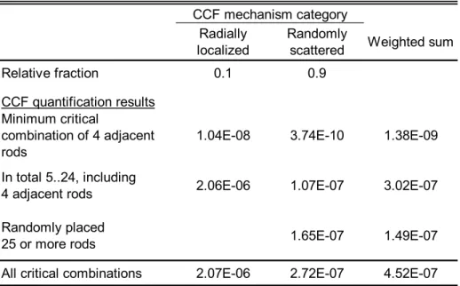
An example is presented in Fig.3.1, showing the quantification results of randomly scattered failures of CRDAs for Barsebäck 1/2. The estimate of pts(25|109) = 1.81E-7 is obtained for the assumed overall failure criterion. It can be seen, that the result is
fortunately not very sensitive to the failure criterion threshold, which was set to 25, maybe a bit pessimistically. Details are explained in the companion document [RS_BRAwr]. There is also presented an approximation to evaluate chances that randomly chosen rods are positioned by coincidence adjacent, forming a critical shape of four adjacent rods (specific criterion for Barsebäck 1/2). This yields to the result of 2.72E-7, i.e. an additional risk mass of about 50% is associated to the number of failed CRDAs being in the range from 4 to 24.
B1/2 Control rods/mechanical jamming, Best estimate
CCF group size CLM parameters
KmMax 109 p_tot 3.20E-05 c_co 0.4
p_xtr 1.00E-07 c_cx 0.8
Km Psg_b Psg_x Psg Peg Pes Pts Remarks
0 1.00E+0 2.99E-7 1.00E+0 9.97E-1 9.97E-1 1.00E+0
1 3.19E-5 9.33E-8 3.20E-5 2.31E-5 2.52E-3 2.88E-3
2 1.94E-7 6.51E-8 2.60E-7 4.32E-8 2.54E-4 3.67E-4
3 7.92E-9 5.24E-8 6.03E-8 3.06E-10 6.42E-5 1.13E-4
4 8.19E-10 4.49E-8 4.58E-8 4.25E-12 2.37E-5 4.85E-5
5 1.45E-10 3.98E-8 4.00E-8 9.14E-14 1.07E-5 2.49E-5
10 9.05E-13 2.73E-8 2.73E-8 1.75E-20 7.45E-7 2.70E-6
15 5.92E-14 2.18E-8 2.18E-8 1.27E-25 1.29E-7 6.86E-7
20 9.53E-15 1.85E-8 1.85E-8 9.24E-30 3.32E-8 2.92E-7
25 2.45E-15 1.63E-8 1.63E-8 3.99E-33 1.12E-8 1.81E-7 Failure criterion
30 8.37E-16 1.46E-8 1.46E-8 7.96E-36 4.85E-9 1.41E-7
40 1.63E-16 1.23E-8 1.23E-8 1.81E-39 1.87E-9 1.10E-7
50 4.80E-17 1.06E-8 1.06E-8 3.94E-41 1.35E-9 9.43E-8
60 1.82E-17 9.45E-9 9.45E-9 4.26E-41 1.21E-9 8.16E-8
70 8.16E-18 8.52E-9 8.52E-9 2.00E-39 1.18E-9 6.96E-8
80 4.12E-18 7.76E-9 7.76E-9 5.35E-36 1.22E-9 5.77E-8
90 2.28E-18 7.14E-9 7.14E-9 1.69E-30 1.35E-9 4.50E-8
100 1.35E-18 6.61E-9 6.61E-9 4.17E-22 1.78E-9 3.00E-8
109 8.85E-19 6.19E-9 6.19E-9 6.19E-9 6.19E-9 6.19E-9
1.0E-10 1.0E-9 1.0E-8 1.0E-7 1.0E-6 1.0E-5 1.0E-4 1.0E-3 1.0E-2 0 25 50 75 100 125 Failure multiplicity Km Failure probability Pts Psg Pes Peg Psg_b Psg_x
3.3 Localized CCF Mechanisms
The basic applications of CLM assume that the analyzed system can be divided up into CCF groups of identical components, each of these groups being internally
homogeneous. The failure dependencies are confined within CCF groups, i.e. the components from different groups are assumed independent between each other.
In practice, these assumptions may not be valid approximations. This section is devoted to a further extension of CLM to situations where the CCF mechanisms are localized, i.e. are most likely to affect adjacent components. Such a situation is specially relevant for CRDAs, as discussed in Section 2.3. A position dependence can arise from local conditions related to coolant flow and turbulence, temperature and neutron flux, or to placing fuel elements/fuel boxes of the same age near to each other. With respect to consequences of failure to insert in reactor scram, adjacent rods are far more critical as compared to randomly placed rods; therefore even weak inhomogeneity in the form of localized failure mechanisms may represent an important risk contribution.
In principle, the position correlation may be of the following two types with respect to the most severely affected rod, called here as Rod ∅:
• Radial correlation: the conditional failure probability of the neighboring rods is dependent on the distance from Rod ∅, but symmetric else
• Band correlation: the failure mechanism affects rods within a band around the core, i.e. rods at about the same radius from the core center; the conditional failure probability of the neighboring rods is again dependent on the distance from
Rod ∅, but significant within the band and small outside the band
These two types differ in the number of vulnerable rod combinations, which is larger in radial correlation. Otherwise the extension of CLM is identical. One more parameter is introduced to describe the weaker dependence for outer shell rods as compared between rods within inner shell. A practical example is presented in Table 3.1. It is extracted from the reference application for Barsebäck 1/2 [RS_BRAwr], and discussed also, in more detail in [CLM_LocZ, Chapter 5].
As shown in Table 3.1, the inner shell is defined to include the four most adjacent rods around Rod ∅, and outer shell the next adjacent, diagonally positioned rods. In the reference application case, no more rods need to be considered, because the MCSs are confined among these one plus eight rods. There are four MCSs each containing Rod ∅, two inner shell rods and one outer shell rod.
It is convenient to present the total failure probability in terms of SGFP entities in the way shown in Table 3.1, because then the condition of other rods beyond the defined outer shell need not be considered. This unburdens the quantification substantially. It should be emphasized, that Psg entities are defined as the probability of specific components failing irrespective of the condition of other components (they may either operate or fail).
Table 3.1 Localized CCF mechanisms, radial correlation: definition of MCS terms and probability variables.
ESCALATION OF CCF AROUND THE WEAKEST ROD Example MCS:
6 2 5 Rod 0
3 0 1 Inner shell rods 1-4 7 4 8 Outer shell rods 5-8
MCS PRESENTATION WITH RESPECT TO CRITICAL COMBINATION OF FOUR ADAJENT RODS
FAILURE PROBABILITY PRESENTATION
where
Psg(Kis,Kos) = Probability that in addtion to Rod 0, specific Kis inner shell and Kos outer shell rods fail
Cmb(Kis,Kos) = Combination coefficients
COMBINATION COEFFICIENTS Kos= 0 1 2 3 4 Kis= 0 0 0 0 0 0 1 0 0 0 0 0 2 0 4 0 0 0 3 0 0 -4 0 0 4 0 0 -2 4 -1 X X X X0. 1. 2. 5 TOP X X X X X X X X X X X X X X X X = + + + 0 1 2 5 0 2 3 6 0 3 4 7 0 1 4 8 . . . . . . . . . . . . { } Pcri P TOP
Cmb Kis Kos Psg Kis Kos Kis Kos = = = =
∑
∑
( , ). ( , ) 0 4 0 4The array of combination coefficients in Eq.(3.6) is derived by standard Boolean reduction of Pr.{TOP(Xi)}, and it is worth while to notice that no truncations or other approximations are involved in this stage of quantification.
The quantification results for the application case of Table 3.1 are presented in Fig.3.2, which shows the calculated Psg entities, and total failure probability Pcri = 2.07E-6, according to Eq.(3.6).
In Fig.3.2, the thick curve shows the failure probability of inner shell components, and thin lines the mixed cases where a specific number of inner shell components fail together with one or more outer shell components. It is of emphasis to notice, that the probability of mixed combination is insensitive to the number of inner shell
components. This makes sense, because if one or more outer shell components fail (in combination with Rod ∅), then it should be almost as likely that any (nonzero) number of inner shell components fail.
The introduced extension of CLM proves to behave in a practically consistent way, and because of requiring only one additional model parameter, is still well manageable. However, it may be difficult to estimate the model parameters from empirical data even in the long term. Thus, the model should in principle be considered as a sensitivity analysis tool, which relies much on engineering judgment. In this respect, it is very positive feature of the model, that once the basic assumptions are fixed, the
mathematical and statistical treatment does not involve any truncations or
approximations which might be difficult to understand and control (an usual problem with many other CCF models).
3.4 Discussion of other approaches
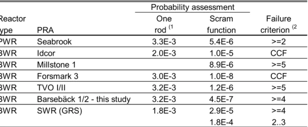
Generally, the insights and conclusions from the earlier review comparison of the CCF models for the use in highly redundant systems [HR_CCFRe] applies also to the ultra-highly redundant systems. More recently, the German PSA study for BWRs
[SWR/PSA] contains a developed approach to quantify multiple mechanical failure of CRDAs by using an extension of Binomial Failure Rate Model (BFRM). The
quantification results are included in the survey to be discussed in Chapter 5. Regarding the methodological details, an actual comparison is not included, partly because the German BWR study does provide only a general description of the method. An orderly comparison would be very interesting to carry out in the continuation.
Barsebäck 1/2 Control rods/Radial CCF, Best estimate
CCF group size CLM parameters
KisMax 4 p_tot 3.20E-3 c_co 0.40
KosMax 4 p_xtr 1.00E-5 c_cx 0.80
p_xto 1.00E-6 u_out 4.12
Cmb
Inner Outer shell components Kos=
shell 0 1 2 3 4 Kis=0 0 0 0 0 0 1 0 0 0 0 0 2 0 4 0 0 0 3 0 0 -4 0 0 4 0 0 -2 4 -1 Psg
Inner Outer shell components Kos=
shell 0 1 2 3 4
Not X0 1.00E+0 1.13E-6 4.59E-7 3.01E-7 2.26E-7
Kis=0 3.20E-3 1.01E-6 4.58E-7 3.01E-7 2.26E-7
1 1.68E-4 9.77E-7 4.57E-7 3.00E-7 2.26E-7
2 2.90E-5 9.57E-7 4.56E-7 3.00E-7 2.26E-7
3 1.08E-5 9.42E-7 4.55E-7 3.00E-7 2.26E-7
4 6.53E-6 9.29E-7 4.54E-7 3.00E-7 2.26E-7 Pcri 2.07E-6
4 3 2 1 Kis=0 1.00E-8 1.00E-7 1.00E-6 1.00E-5 1.00E-4 1.00E-3 1.00E-2 0 1 2 3 4 5 6 7 8 9 10
Failure multiplicity Kis + Kos
3.5 Instructions for CCF analysis of highly redundant systems
Based on the experiences from the earlier CCF analysis for BWR safety/relief valves, and on this project, practically oriented instructions of handbook style has been prepared [CA_HRedI].At this stage, the instructions concentrate on cases similar to safety/relief valve systems of BWR, giving step-wise description of the procedures for data analysis, quantification of CCFs and integration of off-line calculations with the PSA framework. The reference application for Forsmark 1/2 is utilized as consistent example cases in order to illustrate each analysis step. The instructions may later be supplemented in regard to handling of nonhomogeneous and ultra-high redundancy cases such as control rod systems.
A workshop concentrating on CCF analysis methods in highly redundant systems was arranged in 1992, and a training course in 1995 for the PRA groups and specialists within the participating organizations.
4 Reference Application to Barsebäck 1/2
This chapter summarizes the modeling and quantification tasks of the reference application. A more detailed description is presented in the companion work report [RS_BRAwr].
4.1 Overview of RS systems
A functional block diagram of the reactor shutdown systems was presented in Fig.1.1, and will be briefly discussed below. The actual subdivision of the hydraulic scram function into half scram groups A and B is taken explicitly into account as a supplement to the earlier analysis.
Reactor protection system (RPS): Due to an efficient diversity of the process measurements, the main contributors for the automated actuation function are the actuation relay groups, by which the so called SS, V3 and V actuation signals are formed. A total loss of actuation results from a combined failure of the relay groups which provide SS and V actuation signals respectively. It is important to notice, that the process signals come only via SS chain, which then in turn activates V chain by using relay group V3, compare with Fig.1.1.
Hydraulic scram system: The fast reactor shutdown is accomplished by inserting control rods with a hydraulic function to the reactor core. For this function there are 17
hydraulic insertion modules, divided up into two half scram groups A and B. Each hydraulic insertion module is connected to a group of 6 or 7 control rods. There are altogether 109 control rods.
Motor drive shutdown system: The contribution of the drives itself was found small in the PSA. Instead, the failure of power supply is important for the motor drive system (and screw insertion function).
RCP slowdown control system: There are four reactor coolant pumps (RCPs). Their failure to slowdown is dominated by a common PI regulator failure and loss of 24 V DC supply to the regulator. Therefore, a more detailed CCF consideration of the internally redundant parts of RCP slowdown function is not motivated for this system.
Boron injection system: The boron injection is dependent upon operator actuation, which largely determines the reliability of this function. Hence, a more detailed consideration of the component failures is not motivated for this system.
The interface with the electric power supply and other support systems is cared about in the PSA fault tree models. Because of functional diversity of RS systems, the
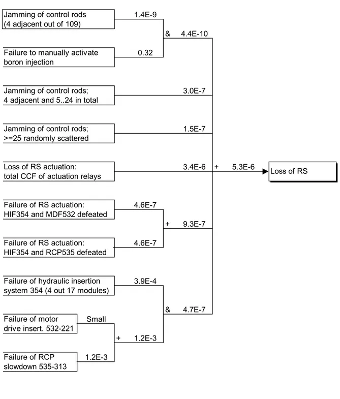
4.2 Failure paths
The failure paths of RS function are presented in Fig.4.1, for the case of transient initiators (loss of main feed, turbine condenser, offsite power). In case of LOCAs, the slow RS cannot be credited: effectively, this means that the failure path of hydraulic scram system (354) becomes a dominant contributor.
4.3 CCF quantification of RS actuation relays
The actuation relays form four separate CCF groups (ARG). The SSA, SSB and V3 relays are normally in rest current state, but V relays in work current state (compare to Fig.1.1). In all other respects the relays are identical. Hence, it is assumed that
• SS actuation relay groups A, B and V3, each with failure criterion 2/3, form together a homogeneous CCF group of 9 relays denoted as ARG/SS-V3
• V actuation relay group, with failure criterion 2/2, can be considered independent of the relays in group ARG/SS-V3, because the important, latent failure
mechanisms are mostly different for relays normally in work current state as compared with rest current state
The success/failure states are grouped according to the functional consequences into following actuation states:
A0 All actuations successful
A1 Hydraulic function 354 defeated
A2 Hydraulic function 354 and motor drives defeated A3 Hydraulic function 354 and RCP slowdown defeated ACCF All actuations fail
These actuation states are mutually exclusive and they can be expressed in terms of relay failure/success combinations. The probability of actuation state can then be derived in terms of using peg(k|n) entities, being calculated for the CCF groups of the relays by CLM. The quantification uses earlier data for actuation relays. The total actuation failure (ACCF) proves to be most important, due to its relatively high probability.
4.4 CCF quantification of hydraulic scram system
As a nominal case, failure criterion ≥4/17 is applied to the hydraulic insertion trains 354. The background to this criterion is that 4 or more failing hydraulic trains means that about 25 or more rods fail to insert; even though randomly positioned, it is likely that at least one critical placement of adjacent rods will be included (similar criterion for control rods will be discussed in the following section). The quantification is done by the normal CLM procedure, using earlier PSA data.