http://www.diva-portal.org
Postprint
This is the accepted version of a paper published in Information and Software Technology. This
paper has been peer-reviewed but does not include the final publisher proof-corrections or journal
pagination.
Citation for the original published paper (version of record):
Lindstrom, B., Offutt, J., Sundmark, D., Andler, S F., Pettersson, P. (2017)
Using mutation to design tests for aspect-oriented models.
Information and Software Technology, 81: 112-130
http://dx.doi.org/10.1016/j.infsof.2016.04.007
Access to the published version may require subscription.
N.B. When citing this work, cite the original published paper.
Permanent link to this version:
Using Mutation to Design Tests for Aspect-Oriented Models
Birgitta Lindstr¨oma,∗, Jeff Offuttb, Daniel Sundmarkc, Sten F. Andlera, Paul Petterssond aUniversity of Sk¨ovde, Sk¨ovde, Sweden
bGeorge Mason University, Fairfax VA, USA cSwedish Institute of Computer Science, Kista, Sweden
dM¨alardalen University, V¨asterås, Sweden
Abstract
Context: Testing for properties such as robustness or security is complicated because their concerns are often repeated in many locations and muddled with the normal code. Such “cross-cutting concerns” include things like interrupt events, exception handling, and security protocols. Aspect-oriented (AO) modeling allows developers to model the cross-cutting behavior independently of the normal behavior, thus supporting model-based testing of cross-cutting concerns. However, mutation operators defined for AO programs (source code) are usually not applicable to AO models (AOMs) and operators defined for models do not target the AO features.
Objective: We present a method to design abstract tests at the aspect-oriented model level. We define mutation operators for aspect-oriented models and evaluate the generated mutants for an example system. Method: AOMs are mutated with novel operators that specifically target the AO modeling features. Test traces killing these mutant models are then generated. The generated and selected traces are abstract tests that can be transformed to concrete black-box tests and run on the implementation level, to evaluate the behavior of the woven cross-cutting concerns (combined aspect and base models). Results: This paper is a significant extension of our paper at Mutation 2015. We present a complete fault model, additional mutation operators, and a thorough analysis of the mutants generated for an example system. Conclusions: The analysis shows that some mutants are stillborn (syntactically illegal) but none is equivalent (exhibiting the same behavior as the original model). Additionally, our AOM-specific mutation operators can be combined with pre-existing operators to mutate code or models without any overlap.
Keywords: Model-based testing, Aspect-oriented model, Mutation testing
1. Introduction and Background
Model-based development is gaining widespread use in the software industry. Models provide a graphical view of software behavior that developers find intuitive. In addition, certain types of models, such as state charts [23], Petri nets [47], and timed automata [5, 9] are use-ful for analysis and verification purposes. Such models can be used by model checkers to verify properties, e.g., to guarantee that a model is free from deadlocks, or to infer the correct ordering of certain events. Moreover, behavioral models can be used to generate test suites that cover the software with respect to model elements or sub paths [6,48]. Consequently, developers can better
∗
Corresponding author: Birgitta Lindstr¨om, University of Sk¨ovde, Box 408, 541 28 Sk¨ovde, Sweden, Tel.:+46 500 448368
Email address: birgitta.lindstrom@his.se (Birgitta Lindstr¨om)
understand and analyze complex behavior by modeling software behavior.
1.1. Aspect-Oriented Modeling
One proposed approach to managing complex be-havioral models is to separate cross-cutting concerns from the main behavior by using aspect-oriented mod-eling[4, 13, 22, 28, 46]. A cross-cutting concern applies throughout multiple locations in the software, and may be crucial to the reliability, performance, security, or ro-bustness of the system. Typical examples include events that require immediate attention, such as intrusion at-tempts or disturbances. Cross-cutting concerns have a tendency to clutter models, leading to complex models that are hard to analyze.
In aspect-oriented modeling, cross-cutting concerns are modeled as aspects, which are separated from the normal behavior, thus creating an aspect-oriented model (AOM). The general idea with an AOM is to model the
normal behavior of the system in a base model, leav-ing the cross-cuttleav-ing concerns to be described in rate aspect models. By modeling these concerns sepa-rately, the behavioral models become cleaner and less cluttered. This makes it easier for a tester to focus on one concern at a time and adjust the level of testing to the level of criticality for the specific concern. An AOM tool then weaves the base model and the aspect mod-els together, in a predefined order, to create a complete behavioral model of the system. The woven model is complex but neither the developer nor the tester need to view it. It is generated and used by model-based tools for model-checking, transformation, and test execution. 1.2. Mutation-Based Testing
We propose to mutate aspect-oriented models (AOMs) to test cross-cutting concerns. In mutation test-ing, a software artifact such as a program or a model is modified to create alternate, usually faulty, versions called mutants [15]. The mutants are created by system-atically applying mutation operators, which are rules for changing syntactic elements. Tests are then designed to cause the mutants to exhibit different behavior from the original version, called killing (or detecting) the mu-tant. Mutation operators either mimic typical program-mer mistakes or make changes that encourage testers to design particularly valuable test inputs.
Test suites are run against collections of mutants to determine the percentage of mutants the tests will kill, called the mutation adequacy score. The mutation ad-equacy score is a coverage criterion, like statement and data flow coverage, but has been found to be stronger than other known criteria and is thus often referred to as a “gold standard” [6]. Mutation is unique among cov-erage criteria in that it not only requires a test to reach a location in the program (the mutated statement), but it also requires the mutated statement to create an error in the program state, and then propagate that error to an output of the program.
Mutation operators have been created for many different languages, including Fortran, Java, and C [2, 30, 31, 37]. Mutation operators have also been de-fined for aspect-oriented programs (source code) in As-pectJ [7, 19, 40, 53]. AsAs-pectJ is an aspect-oriented pro-gramming (AOP) extension to Java and has become a de factostandard for AOP [11]. However, mutation opera-tors defined for aspect-oriented source code are usually not appropriate for models such as finite state machines or state charts.
Mutation operators have also been defined for mod-eling languages such as finite state machines [8, 18, 26], state charts [32, 52], Petri nets [17], and timed automata
[44]. Mutation operators for models focus on the mod-eling elements and can do things like remove an ele-ment or change the target node for an edge. How-ever, these model-level mutation operators do not tar-get aspect-oriented features such as pointcut descriptors (see Section 3).
1.3. Contributions
We describe the use of mutation testing for aspect-oriented models that are expressed as extended finite state machines. Specifically, we describe a fault model for aspect-oriented models and then use the fault model to define mutation operators. We provide an example mutant for each mutation operator and then illustrate the approach using a descriptive application in the form of a video conferencing system in a timed automata imple-mentation for Uppaal [33].
We include and extend work published at the Muta-tion workshop 2015 [36]. In addiMuta-tion to previous work, we present an elaborated fault model, additional muta-tion operators and a thorough analysis of the generated mutants. We have also included a definition of timed automata, which is used in our work.
To our knowledge, there have been no previous at-tempts to define mutation operators targeting the special constructs that are found in aspect-oriented models, or to apply mutation analysis in order to design tests for such models.
Our proposed mutation operators are evaluated and compared to traditional operators through a thorough analysis with respect to the generated, stillborn, equiva-lent, redundant, and duplicated mutants we get as we ap-ply mutation to a small video conferencing system. This approach of evaluation is both a strength and a limita-tion. We do not present any mutation score for the tests we get for this system. Instead, we analyze the mutants we get for the system and show that our new mutation operators gave no overlap to traditional mutation oper-ators, no equivalent or redundant mutants and very few duplicates compared to traditional mutation operators. We got 10% and 1% duplicates respectively for the two sets of new mutation operators compared to 37% for the traditional mutation operators. The reason for having two sets of our proposed mutation operators in the eval-uation is that some of them are not meant to be used together. This will be further explained in Section 3
The remainder of this paper is organized as follows: Section 2 presents a running example of a system model and example aspects. Section 3 presents a fault model for aspect models. Section 4 introduces several muta-tion operators for such models. We also propose using
a large set of pre-existing mutation operators in combi-nation with our new AOM-specific operators.
Section 5 shows examples of how the mutation op-erators can be used in an approach for robustness test-ing ustest-ing timed automata in the Uppaal tool. Section 6 presents an analysis of applying the mutation operators. Related work is discussed in Section 7 and Section 8 concludes the paper.
2. Example AOM System
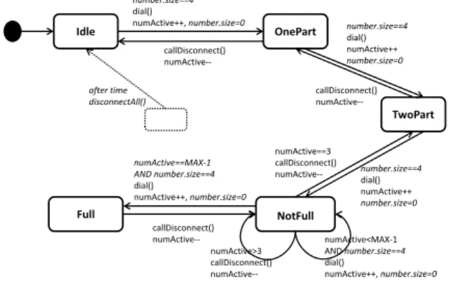
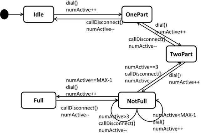
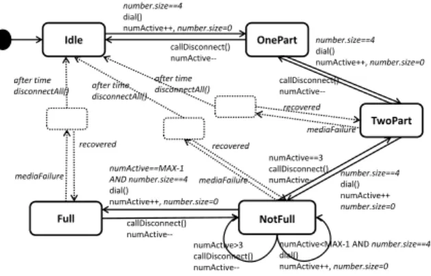
This paper uses a running example of a video confer-encing system. This system has been used by Ali et al. [4], but is slightly modified here so as to better illustrate our mutation analysis approach. In addition to the four states Idle, OnePart, NotFull and Full in the state chart for the base model used by Ali et al. [4], we also have a state TwoPart. The extra state and the transitions to and from it do not change the semantics of the base model or the woven system. The aspect models are identical to the original, except for the notation in the illustrations, where we have chosen to use informal language for sim-plicity. We have also introduced an additional advice to reset the variable number.size after each use. The addi-tional advice is only added to better illustrate our muta-tion analysis approach and has no practical implicamuta-tion to the system behavior since this particular variable will always get a new value before it is read.
We use extended finite state machines (EFSMs) to model the behavior of systems. An EFSM is a tu-ple hL, l0, A, V, Ei, where L is a set of vertices (here
called nodes), l0 ∈ L is the initial node, A is a set
of events, V is a set of (finite domain) integer vari-ables. Assuming B(V) is the set of Boolean combina-tions (or guards) of simple constraints over V and U(V) is the set of arithmetic updates (or actions) over V, then E ⊆ L × B(V) × A × U(V) × L is a set of edges. For an edge e = hl, g, a, u, l0i, we use e.event to denote the
event a, and we say that e is l.outgoing and l’.incoming, gis a guard in B(V) and u is an update in U(V). In the figures, a filled circle points at the initial vertex.
The basic operation of the video conferencing system is shown as an EFSM in the behavioral base model in Figure 1. However, a video conferencing system needs to be robust enough to handle disturbances during a con-ference session. For example, whenever the frequency of video frame loss exceeds a certain threshold, the sys-tem should recover that session. As we have mentioned, instead of cluttering the model with recovery behavior that applies to most of its states, this behavior can best be modeled as an aspect. An aspect consists of point-cuts, advice, and introductions [4].
AOM recap, Base model
Idle OnePart NotFull Full dial() numActive++ numActive==MAX‐1 dial() numActive++ callDisconnect() numActive‐‐ numActive==3 callDisconnect() numActive‐‐ callDisconnect() numActive‐‐ numActive>3 callDisconnect() numActive‐‐ numActive<MAX‐1 dial() numActive++ dial() numActive++ TwoPart dial() numActive++ callDisconnect() numActive‐‐Figure 1: A base model of a video conferencing system
V3 AOM recap, Guard Aspect
Pointcut selecting subset of nodes such that there is an outgoing edge with an event named dial() Pointcut selecting subset of nodes such that there is an incoming edge with an event named dial() Pointcut selecting subset of edges such that there is a triggering event named dial() Before advice: add guard “number.size==4” After advice: add action “number.size=0” number.size==4 number.size=0Figure 2: A simple example of an aspect adding a guard to a subset of edges
A pointcut is a set of elements where the aspect applies, or connects to the base model. The pointcut descriptor is usually a select query written in a formal language and is associated with a single element in the aspect model. The pointcut descriptor selects a non-empty set of elements such as nodes or edges, called joinpointsfrom the base model. For example, consider the aspect model in Figure 2. This aspect will add a guard to any edge in the base model where there is an event “dial()”. Since an edge cannot be modeled with-out the nodes it is attached to, this aspect model has three pointcuts and the pointcut descriptors can be de-fined as follows:
• select vertex v where v.outgoing is labeled with event “dial()”
• select edge e where e.event= “dial()”
• select vertex v where v.incoming is labeled with event “dial()”
We have chosen to use informal language in our illustra-tions since the formal expressions would be tightly con-nected to the modeling language and weaver (the tool combining the base model with the aspect model).
Table 1: Definition of before, around and after advice [4] Modeling
element Before Advice Around Advice After Advice
Node Adding a constraint Replacing the joinpoint Adding a constraint to be to be evaluated before nodes with a new node evaluated on leaving the
entry to joinpoint joinpoint nodes
nodes
Edge Adding a guard to join- Replacing joinpoint Adding an effect with one or point edges. If a guard edges with a new more actions to joinpoint
already exists, the edge edges
additional guard is joined to the existing guard
Event Not applicable Replacing events on Not applicable joinpoint edges with a
new event
Guard and Adding an additional Replacing one or more Same as before advice invariant constraint (conjunct) guards (or invariants)
to the guards (or selected by a pointcut invariants) selected by with a new guard (or
the pointcut invariant)
Action Adding an action to be Replacing the joinpoint Adding an action to be executed before the actions by a new action executed after the
joinpoint actions joinpoint actions
An advice is tied to a pointcut and describes a change to be made at each joinpoint that the pointcut includes. For example, the aspect in Figure 2 adds a guard con-junct and an action appended to the selected edges. An advice can be of type before, around, or after. For each pointcut, there may be at most one advice of each type. 1. A before advice component adds something to the selected elements, such as an extra guard on se-lected edges to be evaluated before traversing any of the selected edges (see Figure 2).
2. An around advice component replaces the selected elements with a new element.
3. An after advice component adds something to the selected element. For example, an extra action may be added to the selected edges to be executed after the transition is triggered (see Figure 2).
The effect of an advice depends on what type of advice it is (e.g., before) and what type of modeling elements (e.g., node) the pointcut includes, see Table 1.
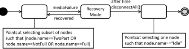
An introduction introduces a new element such as a node or an edge to the model. For example, consider the aspect model in Figure 3. This aspect represents recov-ery from a media failure. The leftmost pointcut selects all nodes in the base model where the event must be handled if it occurs. The rightmost pointcut selects a node from which to restart the system when a timeout occurs. Apart from the two pointcuts selecting elements
V3 AOM recap, Recovery Aspect
after time disconnectAll() mediaFailure recovered Recovery Mode Pointcut selecting subset of nodes such that (node.name==TwoPart OR node.name==NotFull OR node.name==Full) Pointcut selecting one node such that node.name==“Idle”Figure 3: A simple example of an aspect adding recovery behavior
from the base model, the introduction adds four addi-tional elements, three edges and one node, to the model. Introductions are not necessarily just nodes and edges. In our context however, the extra elements are typically nodes (modeling recovery or degraded service) or edges (modeling faults in the environment).
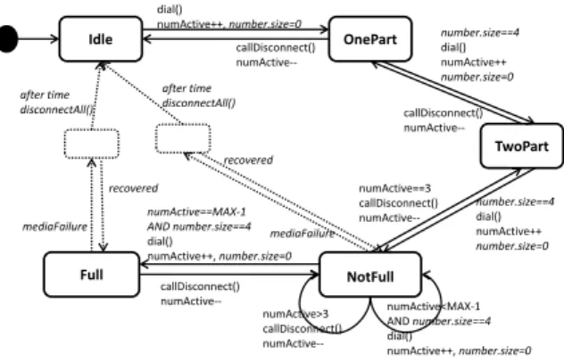
To get a complete model of the system behavior that can be analyzed by a tool, the base model (Figure 1) and the aspect models (Figure 2 and Figure 3) must then be combined by a weaver. The weaver takes as input a base model, a set of aspect models and a weaving directive model, which holds the information of which order to weave each aspect model to the base model. Each aspect model is woven to the base model one aspect model ele-ment (pointcut or introduction) at a time. In case the element is a pointcut, the base model is queried to iden-tify the joinpoints to be included in the pointcut and any before, around or after advice associated with the point-cut descriptor is applied to each of these joinpoints. The output is a woven model [4]. Figure 4 agrees with the
V3 After Weaving the AOM
Idle OnePart NotFull Full after time disconnectAll() numActive==MAX‐1 AND number.size==4 dial() numActive++, number.size=0 callDisconnect() numActive‐‐ callDisconnect() numActive‐‐ callDisconnect() numActive‐‐ numActive>3 callDisconnect() numActive‐‐ numActive<MAX‐1 AND number.size==4 dial() numActive++, number.size=0 after time disconnectAll() mediaFailure mediaFailure number.size==4 dial() numActive++, number.size=0 recovered recovered TwoPart recovered mediaFailure numActive==3 callDisconnect() numActive‐‐ after time disconnectAll() number.size==4 dial() numActive++, number.size=0 number.size==4 dial() numActive++ number.size=0Figure 4: A woven model combining the base model with the two aspect models. Elements that come from the aspects are highlighted in the figure by dotted lines or italics.
resulting woven model described by Ali et al. [4], with the only modification that comes with the added node TwoPartand resetting number.size to 0.
3. Fault Model for Aspect-Oriented Models
Mutation testing inevitably relies on an underlying fault model, detailing the assumptions made regarding potential mistakes that could be made during coding (or, in this case, modeling). The fault model thus constitutes the theoretical foundation of the formulation of muta-tion operators. Below, we propose a fault model tailored for aspect-oriented models.
We assume that aspects already exist in the developed system under test, or can be derived from specifications, to create an aspect-oriented test model to design tests for cross-cutting behaviors such as robustness. Robust-ness is an example of an emergent system property that needs to be addressed in all parts of the system. A tester who tries to design tests to cover robustness would nor-mally have little opportunity to distinguish robustness code from other code. If the tester (or developer) in-stead focuses on the behavior and separates normal and robustness behavior into different models, it becomes easier to design the robustness tests. This can be done as a black-box approach with respect to normal behav-ior, freeing the tester to design the models of robust-ness aspects based on his or her interpretation of what the system should be able to cope with in terms of dis-turbances and erroneous input events. This work thus assumes that aspects can be used or developed for soft-ware testing by means of one of the three approaches below:
A1 The software under test is already modeled as a finite state machine using aspect-orientation in a
model-based development environment. The tester can apply mutation to the pre-existing aspects to create a test suite that properly tests these aspects. A2 The tester only has access to a finite state machine
of the normal behavior of the system. The cross-cutting behavior is handled by other parts of the system, such as the runtime system. The tester can use the existing model as a base model and then create an aspect-oriented test model by designing aspects to be used with this base model.
A3 The tester does not have a behavioral model to start with, and has to create the entire test model from specifications.
Worth to note here is that approaches A2 and A3 come with an overhead since the aspect model or the entire test model needs to be created. As in case of A2 only the aspect models need to be created this may be cost-effective compared to alternative approaches to de-fine how cross-cutting concerns interact with the sys-tem. In case of A3 the overhead is likely to be high, however.
Mutation operators are often designed to mimic typ-ical mistakes such as using the wrong operator or the wrong variable name. The types of mistakes that de-velopers make with cross-cutting concerns vary. Mis-takes such as forgetting to implement it or misinter-preting where a cross-cutting concern applies are com-mon mistakes, which can manifest as different types of faults with respect to the pointcut descriptors in aspect-oriented programs. Such faults have therefore been used to design mutation operators for AspectJ [7, 10, 14, 53]. Given approach A1 for aspect-oriented modeling, a mis-interpretation of where a cross-cutting concern applies can also manifest as different types of faults with respect to the pointcut descriptor. Moreover, even if aspect-orientation is not used (as in approach A2 or A3), such misinterpretation can manifest as the cross-cutting con-cern being implemented at the wrong location or left out where it should have been implemented. Given the lat-ter approaches, an aspect-oriented test model can, there-fore, emulate such faults by introducing faults to the pointcut descriptor or in other ways manipulating the set of joinpoints.
Pointcut Descriptor Fault Types. Figure 5 illustrates the four types of faults for pointcut descriptors, as de-fined by Lemos et al. [34]. These fault types have also been used by Wedyan and Ghosh [53], and Delamare et al. [14]. The grey areas represent the set of join-points that the pointcut selects while the lined areas rep-resent the set of joinpoints that should be selected if the
intended matched 2
1
3 4
Figure 5: The four types of pointcut descriptor faults (1:overlap, 2:dis-joint, 3:subset, 4:superset) [34][14]
pointcut descriptor were correct. The four fault types described in Figure 5 are generic and can be caused by several different types of mistakes. For example, fault type number 3 (subset) can be caused by a pointcut de-scriptor that is too strong, but it can also be caused by mistaking one pointcut for another. The mutation op-erators that we define for pointcuts cover the four fault types.
Advice Fault Types. When it comes to advice, many of the fault types identified for source code in aspect-oriented languages such as AspectJ do not apply to the type of models we use. A typical example is the incor-rect advice type specificationsuggested by Ferrari et al. [19]. Changing the type of an advice (for example, from beforeto after) in an AOM would in most cases lead to models that are syntactically incorrect (or equivalent to the original) and therefore not useful for the analysis. However, binding an advice to a different pointcut than intended or to implement the advice incorrectly can be applied to models as well as code [19][53]. These types of faults may be further elaborated:
1. Advice is incorrectly bound
• Advice is bound to both the intended and un-intended pointcut
• Advice is only bound to an unintended point-cut
• Advice is not bound to any pointcut 2. Advice is incorrectly implemented
• Advice is implemented using the wrong op-erator (e.g., using ’++’ instead of ’- -’) • Advice is referring to the wrong variable,
method or synchronization event
• The advice lacks one or more instructions
Introduction Fault Types. Finally, some fault types are related to introductions. An introduction can be ignored or it can be modeled or implemented incorrectly. For example, an edge can be attached to the wrong node or, a guard might use the wrong conditional operator. Since introduction elements are no different from other model elements, pre-existing mutation operators for models apply. The only difference from the traditional use is that we apply mutation to the aspect models instead of the entire model to test the specific cross-cutting con-cerns.
Given approach A1, any mistakes to the design of an advice will propagate to all parts of the woven model or the resulting code where that advice applies according to the pointcut descriptor. Moreover, any mismatch of selected and intended joinpoints would be caused by a fault in the pointcut descriptor, in case of A1. Hence, mutation operators that apply to the pointcut descrip-tor or to the advice and that take effect throughout the model are reasonable for approach A1. We refer to this as a pointcut approach.
However, given approach A2 or A3, where the soft-ware may not be aspect-oriented and the aspect models are created for testing purposes only, the fault model can be slightly different. It is for example, possible that the behavior modeled as an advice in an aspect by the tester is implemented incorrectly at one location in the software, but correctly at others. Hence, it makes sense to test each advice at each point in the woven model to where it applies. Moreover, a mismatch between intended and selected joinpoints would in case of ap-proach A2 or A3 not be caused by an ill-defined point-cut descriptor (e.g., too strong), but rather to a misinter-pretation of the specification or a simple implementa-tion mistake such as forgetting to implement the behav-ior at one of the intended locations. Hence, mutation operators that apply to single joinpoints are reasonable for approach A2 and A3 since this will ensure that the behavior is tested at each location where the behavior should be implemented. We refer to this as a joinpoint approach.
Mutation operators that delete aspect elements such as pointcuts, introductions, and advice elements ensure that these elements are covered by tests. For example, consider a mutant that changes the leftmost pointcut in Figure 3 (the recovery nodes) so that it selects an empty set of nodes. Killing the mutant ensures that at least one test follows a path that includes a transition to a node la-beled Recovery Mode. Again, coverage can be achieved by covering the modified element at some site where the aspect applies or by ensuring that all of the sites are cov-ered by modifying one joinpoint at a time in different
mutants. For example, mutants can remove node Full, NotFull, and TwoPart from the leftmost pointcut in Fig-ure 3. This approach is useful with approaches A2 and A3.
Mutants for approach A1 can often be created by making small syntactic changes to the aspect models, but creating mutants for approach A2 and A3 may re-quire more effort. This is because a syntactic change made in an aspect in approach A1 applies to all sites in the woven model where that aspect is applied and that particular change makes a difference. To make a syn-tactic change at a single joinpoint, it is necessary for the mutation tool to iterate over the set of joinpoints and treat them in isolation. Joinpoints can often be treated in isolation by the mutation tool, simply by identify-ing the joinpoints that the pointcut in focus will select, in the same order as the weaver. The tool has to take the base model and also the relevant pointcuts and ad-vice in previously processed aspects into consideration when identifying the current joinpoints. When the set of joinpoints is identified, the mutation tool can manip-ulate the pointcut descriptor to include, exclude or re-place these joinpoints one at a time. Sometimes, how-ever, a bigger change to the AOM is required to instruct the weaver to produce the desired woven mutant model. This would be the case if the joinpoint that is subject for mutation is an element, which has been introduced by a preceding aspect and hence, is not part of the base model. This means that some mutants might be very different from the original before weaving if introduc-tions were to be treated with the level of detail as is the case with the joinpoint approach. However, automating such large changes is not trivial and we currently only consider our pointcut approach for introductions.
4. Mutation Operators for Aspect-Oriented Models Based on the fault model presented in the previ-ous section, we propose several mutation operators for aspect-oriented models. We focus on the aspects and the elements (pointcuts, advice and introductions) that they may consist of, as these are syntactic structures that we do not find in other models and hence are not al-ready specifically targeted by other mutation-based ap-proaches for models. We describe the semantics of each mutation operator and then show examples of the re-sulting mutants. The illustrated example mutants are all shown as woven models for two reasons: i) to better illustrate the mutation operator’s effect on the models, which are later used for the analysis and ii) to better fo-cus on the semantics of the mutation operators rather
than their implementation. In practice, the mutation op-erators apply to the aspect models before weaving, as described in the previous section. The mutant models that we get from applying the mutation operators can then be used by a model-checker to generate traces with which these mutants are killed.
4.1. Mutation Operators for Pointcuts
Mutation operators for pointcuts focus on the point-cut descriptors [34] that define the pointpoint-cuts. These AOM-specific mutation operators cover the fault types for pointcut descriptors described in our fault model (Figure 5).
V3 Pointcut Deletion, Example 1
Idle OnePart NotFull Full number.size==4 dial() numActive++ number.size=0 numActive==MAX‐1 AND number.size==4 dial() numActive++, number.size=0 callDisconnect() numActive‐‐ callDisconnect() numActive‐‐ callDisconnect() numActive‐‐ numActive>3 callDisconnect() numActive‐‐ numActive<MAX‐1 AND number.size==4 dial() numActive++, number.size=0 after time disconnectAll() number.size==4 dial() numActive++, number.size=0 TwoPart number.size==4 dial() numActive++ number.size=0 numActive==3 callDisconnect() numActive‐‐Figure 6: The resulting woven mutant when applying PCD to the de-scriptor for the leftmost pointcut in the recovery aspect
Pointcut deletion (PCD): This operator changes the pointcut descriptor so that no element is selected. It cov-ers the scenario in our fault model where the pointcut is ignored. For example, consider the aspect in Figure 3. This aspect has two pointcuts, so PCD will create two mutants. Figures 6 and 7 show the results after weaving with these mutated aspects.
V3 Pointcut Deletion, Example 2
Idle OnePart NotFull Full number.size==4 dial() numActive++ number.size=0 numActive==MAX‐1 AND number.size==4 dial() numActive++, number.size=0 callDisconnect() numActive‐‐ callDisconnect() numActive‐‐ callDisconnect() numActive‐‐ numActive>3 callDisconnect() numActive‐‐ numActive<MAX‐1 AND number.size==4 dial() numActive++, number.size=0 mediaFailure mediaFailure number.size==4 dial() numActive++, number.size=0 recovered recovered TwoPart number.size==4 dial() numActive++, number.size=0 recovered mediaFailure numActive==3 callDisconnect() numActive‐‐Figure 7: The resulting woven mutant when applying PCD to the de-scriptor for the rightmost pointcut in the recovery aspect
The mutant in Figure 6 has a recovery node that can-not be reached. This mutant will be killed by any test where a media failure occurs when a session has at least two participants. The mutant in Figure 7 has recovery nodes that can only be exited if the recovery is success-ful. This mutant will be killed by any test where a media failure occurs when a session has at least two partici-pants and the system fails to recover within the given time frame.
V3 Poincut strengthening, Example
Idle OnePart NotFull Full after time disconnectAll() number.size==4 dial() numActive++ number.size=0 numActive==MAX‐1 AND number.size==4 dial() numActive++, number.size=0 callDisconnect() numActive‐‐ callDisconnect() numActive‐‐ callDisconnect() numActive‐‐ numActive>3 callDisconnect() numActive‐‐ numActive<MAX‐1 AND number.size==4 dial() numActive++, number.size=0 after time disconnectAll() mediaFailure mediaFailure number.size==4 dial() numActive++, number.size=0 recovered recovered TwoPart number.size==4 dial() numActive++ number.size=0 numActive==3 callDisconnect() numActive‐‐Figure 8: Resulting woven mutant when applying PCS to the descrip-tor for the leftmost pointcut in the recovery aspect
Pointcut strengthening (PCS):
By strengthening the pointcut descriptor, we create faults of type 3 (subset) in Figure 5 since the set of join-points selected by the pointcut in the mutant model will be a subset of the set of joinpoints that are selected by the pointcut in the original model. We can strengthen the pointcut descriptor if the select query uses any of the operators OR, ≤, or ≥. An OR is replaced by an AND, ≤ is replaced by <, and ≥ is replaced by >. Furthermore, for each operand in an OR-expression there should be a mutant where that operand and corresponding opera-tor is omitted. If elements exist that are selected by the original pointcut but not by the mutated pointcut, this will result in a reduced set of joinpoints in the mutant. Figure 8 shows the resulting mutant when the point-cut that selects nodes where node.name==TwoPart OR node.name==NotFull OR node.name==Full has been mutated to select nodes where node.name==NotFull OR node.name==Full. This mutant will be killed by a test that triggers error handling in the original but not in the mutant, that is, when media failure occurs during a two part session.
Pointcut weakening (PCW): By weakening the pointcut descriptor, we create faults of type 4 (superset) in Figure 5 since the set of joinpoints that are selected by the pointcut in the original model will be a subset of the set of joinpoints selected by the pointcut in the
mutant model. We can weaken a pointcut descriptor if the select query uses any of the operators AND, <, or >. An AND is replaced by an OR, < is replaced by ≤, and > is replaced by ≥. Furthermore, for each operand in an AND-expression there should be a mutant where that operand and corresponding operator is deleted. Given elements for which the original select query is false and the mutated is true, this will result in more joinpoints in the mutant. This mutant will be killed by a test that executes the aspect due to the weaker condition in the mutant model but not in the original model.
Pointcut replacement (PCR): This mutation oper-ator creates faults of type 1 or 2 (overlap, disjoint) in Figure 5. It may also create faults of type 3 and 4 (sub-set, superset) if one of the pointcuts selects a subset of the joinpoints selected by another pointcut. Each point-cut is replaced by every other pointpoint-cut, where elements are of the same type. In our example system, there are four pointcuts of the type that selects node elements; two in Figure 3 and two in Figure 2. PCR will yield 12 mutants, where each mutant differs from the origi-nal with respect to one of the four pointcuts, which is replaced by one of the other three. For example, PCR will yield one mutant where the leftmost pointcut in Fig-ure 3 selects nodes such that there is an outgoing edge with an event dial(). The set of nodes from which a recovery node can be reached in this particular mutant is therefore changed from {TwoPart, NotFull, Full} to {Idle, OnePart, TwoPart, NotFull}.
Joinpoint deletion (JPD): Just as PCS (PointCut Strengthening), JPD creates faults of type 3 (subset) in Figure 5. The difference is that while PCS focuses on faults in the pointcut descriptor, JPD excludes one join-point at a timefrom the pointcut before weaving. For example, consider the leftmost pointcut in the aspect shown in Figure 3. This pointcut selects three nodes in the base model. Hence, there will be three mutants for this specific pointcut: (i) M1, where the recovery node cannot be reached from state TwoPart, (ii) M2, where the recovery node cannot be reached from state NotFull, and (iii) M3, where the recovery node cannot be reached from the state Full. M3 can only be killed by a test where media failure occurs when there is a maxi-mum number of connected calls. M1 can only be killed by a test where media failure occurs when the current session has exactly two participants. Similarly, apply-ing JPD to the pointcut that adds a guard and an action in the aspect shown in Figure 2 will yield five mutants that all miss the guard and action on one of their edges. This type of mutation operator is useful for cases where the software under test is not already modeled with as-pects (approach A2 or A3), so the implementation may
differ at the various joinpoints (cf. JPI and JPR below). Joinpoint introduction (JPI): This mutation opera-tor adds extra joinpoints to the pointcut. Just as PCW (PointCut Weakening), JPI creates faults of type 4 (su-perset) in Figure 5. The difference is that while PCW focuses on faults in the pointcut descriptor, JPI includes one joinpoint at a timeto the pointcut before weaving. It applies to all elements of the same type as the joinpoints included in the original pointcut. For example, the orig-inal pointcut that selects all edges such that there is a trigger named dial(), selects five of the ten edges in the base model (see Figure 1). Five mutants are created, one for each edge that is not selected by the original pointcut. For example, there will be a mutant where the guard number.size==4 is added to the edge from state OnePartto state Idle as well as to all edges included in the original pointcut.
V3 JPR example
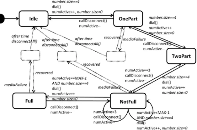
Idle OnePart NotFull Full after time disconnectAll() numActive==MAX‐1 AND number.size==4 dial() numActive++ number.size=0 callDisconnect() numActive‐‐ callDisconnect() numActive‐‐ callDisconnect() numActive‐‐ numActive>3 callDisconnect() numActive‐‐ numActive<MAX‐1 AND number.size==4 dial() numActive++, number.size=0 after time disconnectAll() mediaFailure mediaFailure number.size==4 dial() numActive++, number.size=0 recovered recovered TwoPart recovered mediaFailure numActive==3 callDisconnect() numActive‐‐ after time disconnectAll() number.size==4 dial() numActive++ number.size=0 number.size==4 dial() numActive++ number.size=0
Figure 9: One of the JPR woven mutants
Joinpoint replacement (JPR): This mutation opera-tor combines JPD and JPI by creating all pair-wise com-binations with respect to elements that are selected by a pointcut and the rest of the elements that are of the same type. This mutation operator creates faults of type 1 in Figure 5 (or 2 if the pointcut has exactly one join-point). The difference from PCR is that PCR mimics a fault in the pointcut descriptor and the overlap be-tween intended and matched joinpoints may be small or empty, whereas JPR gives an overlap between intended and matched joinpoints that is almost complete. Each mutant differs from the original by having one joinpoint replaced by an element of the same type. For example, the leftmost pointcut in the recovery aspect (Figure 3) selects three of the five nodes. Hence, there will be six JPR mutants for this pointcut. Figure 9 shows an exam-ple of a JPR mutant where the node OnePart is selected instead of node TwoPart.
4.2. Mutation Operators for Advice
We have two approaches for designing advice mu-tation operators: (i) the advice is mutated at all of its sites in a single mutant, and (ii) one mutant is created for each place where the advice applies. If a pointcut has more than one piece of advice, for example, a be-foreadvice and after advice, these will be mutated sep-arately regardless of the approach. When the first ap-proach is used, at most three mutants will be created for each pointcut (one per advice) and the mutation opera-tor will apply at all elements pointed out by the pointcut descriptor. With the second approach, the advice should only be mutated at one of the sites pointed out by the pointcut at a time. Given J joinpoints, the second ap-proach means that there will be at most 3 ∗ J mutants. 4.2.1. AOM-Specific Operators for Advice
The AOM-specific mutation operators address the part of our fault model where an advice is ignored or bound to an incorrect pointcut.
Advice deletion at pointcut (ADP): Consider Figure 2. The center pointcut with advice selects five edges but applying ADP to this aspect model will create only two mutants, one for the before advice and one for the after advice. The first will not add the guard number.size==4 to any of the five edges. A test can kill this mutant if any of the calls tries to connect with an incorrect number. The second mutant will not add the assignment num-ber.size=0 to any of the five edges. This mutant is trivial since it will be killed by any test that visits any of these edges.
Advice deletion at joinpoint (ADJ): Consider Fig-ure 2 again. Applying ADJ to this aspect model will yield ten mutants. Five mutants will delete the guard number.size==4 on one of their edges and five mutants will delete the assignment number.size=0 on one of their edges. For example, one mutant will delete the guard on the edge (TwoPart, NotFull). This mutant can be killed by a test if any call tries to connect with an incorrect number when the session has exactly two participants.
Advice introduction at pointcut (AIP): Consider Figure 2 again. This is the only aspect model in our example that has a pointcut with advice. It has a be-fore and an after advice. It is also the only pointcut descriptor that selects a set of edges. Assume that there is a second pointcut that also selects a set of edges and has no before or after advice. AIP would then create one mutant where the before advice is copied to the sec-ond pointcut and one mutant where the after advice is copied to the second pointcut. AIP applies to any pair of pointcuts which joinpoints are of the same type (that
is, selects the same type of model elements), in the same scope, and with a type of advice (e.g., before) that orig-inally only existed in one of them.
Advice introduction at joinpoint (AIJ): AIJ is the same as AIP except it applies to a single joinpoint in each mutant.
Advice replacement at pointcut (ARP): It is possi-ble to replace a before advice by another before advice. The replacing advice should be an existing advice of the same type as the advice being replaced. For example, a before advice for a pointcut of a set of nodes is replaced by the before advice for every other pointcut that is a set of nodes, has a before advice, and is in the same scope. Advice replacement at joinpoint (ARJ): ARJ is the same as ARP except it applies to a single joinpoint in each mutant.
4.2.2. Code-Level Mutation Operators
Mutation has traditionally been applied to code [16, 39], where individual statements in a program are mutated. We call these code-level mutation operators and emphasize that they were not specifically designed for aspects in aspect-oriented software. In our research, these operators are not actually applied to code, but to the model, however we do not wish to introduce a term and follow the established convention of calling them code-level.
The code-level mutation operators address the part of our fault model where an advice is implemented incor-rectly. There are several traditional mutation operators that apply to advice elements, such as the ROR operator, which replaces relational operators by other relational operators plus two mutation-specific operators [38, 39]. • ROR replaces relational operators in the aspect models by other relational operators plus falseOp, and trueOp, which replace the expression with true and false respectively. For example, m <= n is re-placed by m < n, m== n, m > n, m >= n, m! = n, trueand false.
• RORJ is the same as ROR but is applied to the ad-vice at one joinpoint in each mutant
• COR replaces logical operators by other logi-cal operators plus leftOp, rightOp, trueOp, and falseOp, where leftOp and rightOp replace the ex-pression with the left and right operand respec-tively. For example, m&&n is replaced by m||n, m&n, m|n, mˆn, m, n, true and false.
• CORJ is the same as COR but is applied to the ad-vice at one joinpoint in each mutant
• AOR replaces arithmetic operators by other arith-metic operators plus leftOp, rightOp, and mod. For example, m+n is replace by m-n, m*n, m/n, m**n, m, n, and m%n.
• AORJ is the same as AOR but is applied to the ad-vice at one joinpoint in each mutant
• SVR replaces each variable reference by every other variable of appropriate type declared in cur-rent scope. For example, x=m+n is replaced by x=m+m, m=m+n, x=n+n, n=m+n, x=x+n and x=m+x.
• SVRJ is the same as SVR but is applied to the ad-vice at one joinpoint in each mutant
• ASR replaces each assignment operator by other assignment operators. For example, m+=3 is re-placed by m-=3, m*=3, m/=3, m%=3, m& = 3, m|= 3, mˆ=3, m <<= 3, m >>= 3 and m >>>= 3. • ASRJ is the same as ASR but is applied to the
ad-vice at one joinpoint in each mutant
Ferrari et al. [20] defined some additional mutation operators for advice in source code. We have not used these in our work since the syntax as well as the se-mantics of advice in an aspect-oriented model differs depending on what type of model element it is applied to, and whether the advice is a before, around, or after advice. Hence, these mutation operators would usually generate mutants that are syntactically incorrect if ap-plied to an AOM.
4.3. Mutation Operators for Introductions
Introduction deletion (IDL): An IDL mutant deletes each introduction element in the aspect model in turn. IDL addresses the part of our fault model where intro-ductions are ignored. IDL mutants are killed by any test that visits the deleted element. Our example aspect-oriented model has four introductions; three edges and one node. Hence, IDL will yield four mutants. For ex-ample, one mutant will have only one outgoing edge from the recovery node leading to a timeout.
Apart from IDL, there are several mutation operators defined for FSMs and source code that are not specific for aspect-oriented models but also apply to introduc-tion elements. We describe these in Secintroduc-tions 4.3.1 and 4.3.2
4.3.1. Model-Level Mutation Operators
Several mutation operators for models address the part of our fault model where introductions are mod-eled incorrectly. We call these model-level mutation operators and emphasize that they target modeling ele-ments but are not specifically designed for introductions in aspect-oriented models.
An introduction is a model element, thus mutation operators defined for model elements apply to introduc-tions. Some of these mutation operators were proposed by others and some are new to this paper.
The pre-existing operators that we use are 1, 2, 3, 4, and 5 below. Items 8 and 9 are variants of pre-existing operators and items 6, 7, 10 and 11 are new to this re-search. All the pre-existing operators were originally defined for general FSMs, not aspect models.
1. RTN replaces each target node for edge introduc-tions by other nodes [26, 35, 50]
2. RSN replaces each starting node for edge introduc-tions by other nodes [35, 50]
3. RSI replaces each synchronization event at edge introductions by other synchronization events [18, 29, 50]
4. DSI deletes each synchronization event at edge in-troductions [18, 50]
5. DGI deletes each guard at edge introductions [29] 6. RGI replaces each guard at edge introductions by
other guards
7. SSI replaces each send with a receive and each re-ceive with a send at synchronization events on edge introductions
8. DAI deletes each action at edge introductions [32] 9. RAI replaces each action at edge introductions by
other actions [32]
10. DIN deletes each invariant at node introductions 11. RIN replaces each invariant at node introductions
by other invariants
4.3.2. Code-Level Mutation Operators
The code-level operators address the part of our fault model where introductions are implemented incorrectly. Just as advice elements, introductions can come with constraints, guards, actions etc. containing relational, arithmetic or logic expressions. The traditional code-level mutation operators of ROR, COR, AOR, SVR, and
ASR that we suggest for advice also apply to introduc-tions. Since there is no overlap between introductions and pointcuts, there is no redundancy between applying these operators both to advice and to introductions.
We have discussed the possibility of applying mu-tation operators to single joinpoints rather than point-cuts. This is fairly straightforward since a pointcut de-scribes a set of joinpoints and each advice is mapped to a pointcut. It is therefore possible to iterate over a set of joinpoints and treat them differently by modifying the aspect models. However, introductions are elements in the aspect model that have no corresponding elements in the base model, there is no set to iterate over before the weaving process. A fine-grained mutation approach for introductions may therefore require integration with or at least control of the weaver and is not addressed here. Mutating an introduction will therefore affect all parts of the woven model where that element is introduced. 4.4. Choice of Mutation Operators
The mutation operators that we have defined in pre-vious sections are in most cases defined for two di ffer-ent approaches. For example: PCD vs JPD, ADP vs ADJ and ROR vs RORJ. Given the approach, the tester should chose to use the set of mutation operators that works at a pointcut/aspect level or at a joinpoint level. The choice of which set of mutation operators to se-lect depends on the fault model and this in turn depends on whether the software is aspect-oriented to begin with (approach A1) or whether the aspects are something that is created for a test model (approaches A2 and A3). In the first case, it makes sense to assume that a fault in an aspect propagates to all sites in the woven model to which the faulty element applies during weaving. For example, if an advice to add a guard at some edge is missed, this guard will be missed at all edges selected by the pointcut descriptor. Hence, a mutation opera-tor such as ADP would be sufficient to detect this fault. On the other hand, if the aspects are only used as a test model it would make sense to apply ADJ in order to test that the guard is present at each edge selected by the pointcut descriptor.
5. Application to Robustness Testing
This section describes an example use of our pro-posed approach for robustness testing of systems mod-eled in timed automata (TA). TA is used by engineers to specify and verify real-time systems.
The primary focus for this work is to use model-checking algorithms to kill mutants, not to verify time-liness or performance. We are particularly interested
in embedded real-time systems, where there often is a timing aspect associated with robustness. For example, recovery of a subsystem might have an associated dead-line. For this reason, we selected TA as a suitable model for our approach.
Applying the previously defined mutation operators to the TA modeling language will change the scope or domain of some operator slightly. E.g., the domain of SVR is extended to include clock variables used in TA, and the scope of the mutation operator COR is ex-tended to encompass some additional conditional oper-ators used in TA. This is described in Section 6.2. 5.1. Timed automata
This section provides a brief but necessary introduc-tion to TA. For more details on these concepts, see Bengtsson and Yi [9] or Hessel et al. [25].
In a timed automaton, clocks are represented by a fi-nite set of real-valued variables C and events are repre-sented by a finite alphabetΣ. Let B(C) denote the set of Boolean combinations of clock constraints of the form x ∼ nor x − y ∼ n, where x, y ∈ C, n is a natural number and ∼ represents one of the relational operators {<, ≤, =, ≥, >}.
A timed automaton (A) over events and clocks (Σ, C) is a tuple hN, l0, E, Ii where:
• N is a finite set of vertices (here called nodes) • l0∈ N is the initial node
• E ⊆ N × B(C) ×Σ × 2C× N is a set of edges
• I : N → B(C) assigns invariants to nodes
The semantics of a timed automaton is a timed tran-sition system over states of the form hl, ui, where l ∈ N and u is a clock assignment of all clocks in C to non-negative real-numbers. The initial state is hl0, u0i, where
u0is the clock assignment that assigns all clocks in C to
0. Transitions are defined by two rules:
1. (discrete transitions) hl, ui →a hl0, u0i if
hl, g, a, r, l0i ∈ E, u ∈ g, u0 = [r 7→ 0]u and
u0∈ I(l0)
2. (delay transitions) hl, ui→ hl, u ⊕ di if u ∈ I(l) andd (u ⊕ d) ∈ I(l) for a non-negative real d ∈ <+ where u ⊕ d denotes the clock assignment that maps each clock x in C to the value u(x)+ d, and [r 7→ 0]u is the clock assignment u with each clock in r reset to zero.
Timed automata have two kinds of transitions, thus two transition rules: the discrete transition, which is an instant move from one node to another that is enabled when the clocks satisfy the guard on the edge, and the delay transition, which increments the clocks but does not include a move to another node.
A run of a timed automaton A = hN, l0, E, Ii
with initial state hl0, u0i over a timed trace ξ =
(t1, a1)(t2, a2)(t3, a3)... is a sequence of transitions: hl0, u0i d1 →→ hla1 1, u1i d2 →→ hla2 2, u2i d3 →→ hla3 3, u3i...
satisfying the condition t1= d1and ti= ti−1+ difor all
i ≥ 1. The timed language L(A) is the set of all timed traces ξ for which there exists a run of A over ξ.
A network of timed automata A1k...kAn over (Σ, C)
is the parallel composition of n timed automata over (Σ, C), where components are required to synchronize on delay transitions and discrete transitions are required to be synchronized on complementary actions. An ac-tion a? is complementary to a!.
5.2. Example System
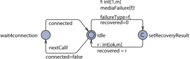
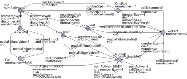
We manually translated the woven video conferenc-ing system to a timed automaton for Uppaal (Figure 10). M¨ucke and Huhn [41] describe how to transform a UML state chart to Uppaal. We then used the Uppaal model checker to verify its behavior [33]. In Uppaal, a dou-ble circle denotes the initial node. In addition to the woven system, we also have models that implement the system’s environment, including calls and disturbances that cause media failures (Figures 11 and 12). We used the Uppaal simulator to execute the test scenarios and to generate the traces that we discuss in our examples.
Figure 13 gives an overview of the AOM mutation process. Mutation operators are applied to the aspect models before weaving, creating a set of aspect mutants. The weaving process creates a set of woven mutants by using aspect mutants instead of the original aspect model. An analysis is then performed to identify traces that can be traversed when using the original version of the woven model but not in the mutant version or vice versa. This can be viewed as a form of weak muta-tion since the mutant is killed based on its internal state. Identified traces can then be transformed to test cases.
The process described in Figure 13 is currently semi-automated, as both mutation and weaving have been conducted manually in our study. There is a lack of au-tomated tool support when it comes to AOM. Weavers for AOM exist but are typically in-house built or imple-mented within a testing framework and not available, [12, 21, 27, 45, 49, 54].
R3 x <= limit R2 x <= limit R1 x <= limit Full numActive==MAX NotFull 2<numActive<MAX TwoPart numActive==2 OnePart numActive==1 Idle numActive==0 mediaFailure[video]? x=0 mediaFailure[video]? x=0 mediaFailure[video]? x=0
recovered == ok and x <= limit
mediaFailure[audio]? x=0 recovered == ok and x <= limit mediaFailure[audio]? x=0 recovered == ok and x <= limit mediaFailure[audio]? x=0 recovered!=ok and x>=limit disconnectAll! numActive=0 recovered!=ok and x>=limit disconnectAll! numActive=0 recovered!=ok and x>=limit disconnectAll! numActive=0 numActive < MAX-1 and numberSize==4 dial? numActive++, numberSize=reset() numActive>3 callDisconnect? numActive--callDisconnect? numActive--callDisconnect? numActive--callDisconnect? numActive--callDisconnect? numActive--numActive == MAX-1 and numberSize==4 dial? numActive++, numberSize=reset() numberSize==4 dial? numActive++, numberSize=reset() numberSize==4 dial? numActive++, numberSize=reset() numberSize==4 dial? numActive++, numberSize=reset()
Figure 10: A timed automata model of the woven system
Ok2dial Connected Idle dial! connected=true nextCall? numberSize=mySize disconnectAll? callDisconnect!
Figure 11: A timed automata model of a conference participant
wait4connection Idle setRecoveryResult
connected nextCall! connected=false r : int[ok,m] recovered = r f: int[1,m] mediaFailure[f]! failureType=f, recovered=0
Figure 12: A timed automata model of a driver triggering new calls and generating disturbances
Robustness is defined as “The degree to which a sys-tem or component can function correctly in the presence of invalid inputs or stressful environment conditions” [1]. Systems can be stressed in many different ways, such as frame loss, noise, synchronization mismatches and lost connections [4]. Each type should of course be identified and addressed by the aspect models. A major difference between the previous examples and the timed automata model used here is, therefore, that the timed automata model distinguishes between two types of fail-ures: audio and video. This example, with two types of failures, is used to illustrate the approach. With all types of media failures included, a fully woven model would
Weaving Aspect model Base model Environment model Mutating Aspect mutantmutantAspect Aspect
mutants
Aspect mutantmutantAspect Woven
mutants Woven
original
Analyzing
Aspect mutantmutantDetecting Aspect
traces
Weaving
Figure 13: Overview of the AOM mutation process
be too cluttered to show in a single figure.
Figure 10 shows a timed automata model of the wo-ven video conferencing system. Figure 11 shows a timed automata model that describes the behavior of participants in the video conference. A participant con-nects to the system by taking the transition labeled dial! from Ok2dial to Connected. This transition is syn-chronized with a transition labeled dial? in the system shown in Figure 10. In the same way, a transition from
Connectedto Idle is triggered by a synchronization on callDisconnect. A disconnectAll is a broadcast signal triggered by the system. All participants that are con-nected when this broadcast occurs will take a transition to their Idle node.
Figure 12 shows a timed automata model of a sim-ple driver for the video conferencing system. The driver triggers new calls as well as media failures of di ffer-ent types. The failureType variable is set by selecting a value between 1 and m, where m is the number of failure types. Each possible value of failureType can be mapped to a specific type of disturbance that this system should handle. As mentioned, our example system has two types of disturbances, audio and video. When the driver triggers a media failure, it immediately contin-ues by setting the variable recovered to a value between 0 and m, where 0 == ok (i.e., successfully recovered) and a higher number indicates a persisting failure of the specified type (1-m). For example:
• A trace where failureType is set to 1 and recovered is set to 0, maps to a test with an audio failure that is successfully recovered.
• A trace where failureType is set to 1 and recovered is set to 1, maps to a test where an audio failure persists and can be used to verify that the system implemented a timeout and can handle it by reset-ting the system.
• A trace where failureType is set to 2 and recovered is set to 1, maps to a test where there is a video fail-ure followed by an audio failfail-ure that is persistent. Such test is useful to verify that a persisting failure is handled by a timeout and reset, independent of whether the persistent failure is of the same type that caused the transition to the recovery mode in the first place.
Here, we show three example robustness mutants and discuss their use. The mutants can be used to create tests or to evaluate a set of tests with respect to their mutation score. Both approaches employ the trace from the environment (driver and participants).
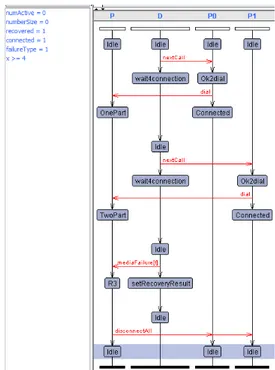
Consider the trace in Figure 14. This is a graphical view of a trace of an execution of the processes P, D, P0, and P1, where P is the system shown in Figure 10 and D is the driver shown in Figure 12. P0 and P1 are in-stances of the template participant shown in Figure 11. The boxes in Figure 14 show nodes, the vertical arrows show transitions, and the horizontal arrows show syn-chronization between automata. In the upper left corner of the figure is a list of variables and their values af-ter the last transition, where x is a clock variable that
Figure 14: A graphical view of a trace
models the timer. The time limit is set to four. This spe-cific trace shows two connections followed by an audio failure (failureType=1) that persists (recovered=1) and leads to a timeout (x >= 4) and a disconnectAll. 5.3. Example Mutants and Tests
The trace in Figure 14 is a result of executing a test scenario in the Uppaal simulator using the original ver-sion of the system. Consider the PCD (PointCut Dele-tion) robustness mutant in Figure 15. The crossed and grayed out portions in the figure have been deleted in the mutant. Enforcing the same trace in the mutant model will lead to a deadlock since it is not possible to take the last transition (P:R3, Idle) in the mutant model, so nei-ther P0 or P1 can receive the broadcast signal and take the transition to their Idle states. Hence, this trace is an abstract test that kills this mutant. A corresponding test scenario, to be executed on the real system, would focus on the sequence of interactions between the system (P) and its environment, in our case the driver and the par-ticipants. The interactions can be translated to real input events and used to test the software system, assuming that the events (calls and disturbances) can be produced and controlled with respect to the order in which they start and stop, and to the type and persistence of the dis-turbance (exceeding the time limit). Such concrete tests can preferably be realized as a scenario played by an
R3 x <= limit R2 x <= limit R1 x <= limit Full numActive==MAX NotFull 2<numActive<MAX TwoPart numActive==2 OnePart numActive==1 Idle numActive==0 mediaFailure[video]? x=0 mediaFailure[video]? x=0 mediaFailure[video]? x=0
recovered == ok and x <= limit
mediaFailure[audio]? x=0 recovered == ok and x <= limit mediaFailure[audio]? x=0 recovered == ok and x <= limit mediaFailure[audio]? x=0 recovered!=ok and x>=limit recovered! oovere disconnectAll! d numActive=0 numAct x < recovered!=ok overed!= re and x>=limitnd x disconnectAll!nne numActive=0ve=0 recovered!=ok and x>=limit recovered! oovere disconnectAll!l numActive=00 numActive < MAX-1 and numberSize==4 dial? numActive++, numberSize=reset() numActive>3 callDisconnect? numActive--callDisconnect? numActive--callDisconnect? numActive--callDisconnect? numActive--callDisconnect? numActive--numActive == MAX-1 and numberSize==4 dial? numActive++, numberSize=reset() numberSize==4 dial? numActive++, numberSize=reset() numberSize==4 dial? numActive++, numberSize=reset() numberSize==4 dial? numActive++, numberSize=reset()
X
X
X
Figure 15: Timed automata mutant where a pointcut is deleted (PCD)
R3 x <= limit R2 x <= limit R1 x <= limit Full numActive==MAX NotFull 2<numActive<MAX TwoPart numActive==2 OnePart numActive==1 Idle numActive==0 mediaFailure[video]? x=0 mediaFailure[video]? x=0 mediaFailure[video]? x=0
recovered == ok and x <= limit
mediaFailure[audio]? x=0 recovered == ok and x <= limit mediaFailure[audio]? x=0 recovered == ok and x <= limit mediaFailure[audio]? x=0 recovered!=ok and x>=limit disconnectAll! numActive=0 recovered!=ok and x>=limit disconnectAll! numActive=0 recovered!=ok and x>=limit disconnectAll! numActive=0 numActive < MAX-1 and numberSize==4 dial? numActive++, numberSize=reset() numActive>3 callDisconnect? numActive--callDisconnect? numActive--callDisconnect? numActive--callDisconnect? numActive--callDisconnect? numActive--numActive == MAX-1 numberSize==4 dial? numActive++, numberSize=reset() numberSize==4 dial? numActive++, numberSize=reset() numberSize==4 dial? numActive++, numberSize=reset() numberSize==4 dial? numActive++, numberSize=reset()
---Figure 16: Timed automata mutant where an advice is deleted at a single joinpoint (ADJ)
environment simulator that interacts with the software system.
Consider the ADJ robustness mutant in Figure 16. The mutant does not have the guard numberSize==4 (crossed and grayed out) on the edge between NotFull and Full. Hence, it is possible to get a trace in the mutant to a state where numberSize!=4 and a transi-tion from NotFull to Full is enabled. This transitransi-tion is not possible in the original model and the test scenario would actually lead to a deadlock state. On the other hand, the mutant cannot reach this deadlock state.
We can translate candidate test scenarios to candidate test traces as a sequence of discrete transitions that Up-paal can accept. By enforcing these traces on the origi-nal as well as the mutant models, we can identify which candidates tests are effective and which mutants they
de-Environment
model mutant Aspect mutant Aspect Live mutant Woven
original
Analyzing
Aspect mutant Detecting mutant Aspect
trace Aspect mutant mutant Aspect Aspect
mutant mutant Aspect Candidate test trace Aspect
mutant mutant Detected Aspect mutant
Figure 17: Identifying the detecting traces.
tect. This way we can either create a strong test suite based on the traces that are effective or evaluate an
ex-isting test suite with respect to its mutation adequacy score (detected/all), see Figure 17.
Candidate test scenarios can be: (i) an existing test suite, (ii) defined by the tester (iteratively), (iii) ran-domly generated as candidate traces by simulation of the model, or (iv) defined by the model-checker (traces to error states associated with the mutation). Candi-date test traces that detect mutants are included in the test suite, while others are discarded. We currently use approach (iv) and search for error states (mainly dead-locks) in both original and mutant versions. However, the process described in Figures 13 and 17 is indepen-dent on how the candidates are generated. Another op-tion to generate candidate test traces is to instrument the aspect models and then use the model checker to iden-tify traces to such instrumented locations (or locations where an instrumentation is missing) in the woven mod-els.
Finally, consider the IDL robustness mutant in Figure 18. This mutant has no edge to the recovery node for the failure type video (again showed in figure as crossed and grayed out). Hence, this mutant is killed by a test with a media failure of this type when at least two participants are active.
6. Analysis of Mutating an Example System
This section shows how the mutation operators de-fined in Section 4 can be applied to a working system. We first demonstrate the application of our novel AOM-specific operators, then existing mutation operators for code, and finally existing mutation operators for mod-els. Subsection 6.4 presents an analysis of the mutants created for our example system.
Not all generated mutants are useful when mutation is applied to software, independent of whether mutation is applied to source code or to a model. Some mutants are syntactically illegal and thus, in our case, are not ac-cepted by the model checker. We refer to such mutants as stillborn. Some mutants are equivalent to the original software, meaning that for each possible input the orig-inal and the mutant version will show the exact same behavior. Hence, such mutants cannot be distinguished from the original by any test. Some mutants are equiva-lent to each other but not to the original and are referred to as redundant. If two mutants are redundant, then any test that detects one of them is guaranteed to also de-tect the other. Finally, two mutants can be syntactically identical to each other. We refer to such mutants as du-plicates.
Table 2: Overview of the number of mutants generated for each AOM-specific operator
Mutants from the Pointcut Approach Operator Generated Equivalent Stillborn Remaining
PCD 5 0 2 3
PCS 5 0 0 5
PCW 0 0 0 0
PCR 12 0 6 6
ADP 2 0 0 2
Mutants from the Joinpoint Approach Operator Generated Equivalent Stillborn Remaining
JPD 17 0 8 9
JPI 13 0 2 11
JPR 43 0 18 25
ADJ 10 0 0 10
Mutants Relevant to Both Approaches Operator Generated Equivalent Stillborn Remaining
IDL 5 0 0 5
Sum 112 0 36 76
(29 or 88) (8 or 28) (21 or 60)
Sum Unique 68 (18 or 59)
6.1. AOM-Specific Mutation Operators
For our example system, the novel mutation operators that specifically targets AO features yield a total of 112 mutants (see Table 2).
However, the mutation operators should not all be used together. Depending on whether there is a need to test all the joinpoints individually or not, two di ffer-ent sets of mutation operators should be used (approach A1 versus A2 or A3). Only IDL applies to both sets. We give the numbers for both the pointcut approach and the joinpoint approach in Table 2. 36 of the generated mutants are syntactically illegal (stillborn), thus cannot be used. All the stillborn mutants involve a change to the set of joinpoints selected by the pointcuts in the add guard aspect. The three pointcuts in this aspect depend on each other, so changing the set of joinpoints for one pointcut in this aspect while keeping the other pointcuts unchanged sometimes lead to stillborn mutants.
None of the mutants are equivalent to the original so 76 of the generated mutants can be analyzed. Eight of the 76 are duplicates. However, since we use two dif-ferent sets of mutants depending on whether we employ a pointcut approach or a joinpoint approach, only four of these are true duplicates and can be removed, three for the pointcut approach and one for the joinpoint ap-proach (see Table 3). The mutants that cannot be re-moved are shown in parentheses in Table 3. We found seven types of duplicates:
1. PCD and PCS: Two PCS mutants have an OR re-placed by an AND in the leftmost pointcut in the
![Figure 5: The four types of pointcut descriptor faults (1:overlap, 2:dis- 2:dis-joint, 3:subset, 4:superset) [34][14]](https://thumb-eu.123doks.com/thumbv2/5dokorg/4808336.129253/7.892.129.392.167.318/figure-types-pointcut-descriptor-faults-overlap-subset-superset.webp)