BACHELOR THESIS
IN ELECTRONICS
15 CREDITS, BASIC LEVEL
School of Innovation, Design and EngineeringABSTRACT
Enics Sweden AB, Västerås, is an electronics manufacturing services company with its main business in manufacturing electronics. Most, if not all, electronic devices that are manufactured are being widely tested before delivery to ensure proper functionality. Often during tests a large number of signals are measured by one to a few digital multimeters and are therefore controlled through relays. Relays are also used when applying stimuli with high currents or voltages to the unit under test.
This work have been focused on finding a concept, including designing and producing a prototype, for a modular relay control system for use in fabrication of small test systems and for use when there is a need for adding more relays to an existing system.
SAMMANFATTNING
Enics Sweden AB, Västerås, är ett företag inriktat på att tillverka elektronik och där tillhörande tjänster. De flesta, om inte alla, produkter som tillverkas genomgår omfattande tester innan leverans för att säkerställa att produkterna är fullt funktionsdugliga. Ofta vid test så mäts ett flertal signaler med en eller ett par digitala multimetrar, därför styrs dessa mätsignaler genom reläer. Reläer används också när man applicerar stimuli i form av höga strömmar eller spänningar till enheten som testas.
Detta arbete har koncentrerats på att ta fram ett koncept, inklusive att utforma och producera en prototyp, för ett modulert relästyrsystem i syfte att användas vid framtagning av små testsystem och vid utbyggnad av redan befintliga testsystem där det finns ett behov av fler reläer.
Date: 17 May 2010
Carried out at: Enics Sweden AB Advisor at MDH: Mikael Ekström
Advisor's at Enics Sweden AB: Pontus Klarsjö and Per Nilsson Examinator: Mikael Ekström
PREFACE
I would like to thank my supervisors at Enics for supporting me with all, big as well as small, issues and problems encountered during this project and for accepting that it took quite a lot more time than first intentioned. I would also like to thank everyone who supported me and encouraged me to finish a project that sometimes felt like a never ending story.
Also many thanks to my production manager who have been supportive and let me do parts of this work during my regular working hours.
Any thoughts and opinions about this work could be sent to one of the following e-mail addresses: mikael.ivarsson@enics.com or mikael_ivarsson@hotmail.com.
Västerås, May 2010 Mikael Ivarsson
ABBREVIATIONS
Abbreviation Explanation
A/D Analogue to Digital converter
BJT Bipolar Junction Transistor
BOM Bill Of Materials
C Common (terminal(s) on relays)
CAD Computer-Aided Design
CPLD Complex Programmable Logic Device
DPDT Double Pole, Double Throw
D-SUB D-Subminiature
EEPROM Electrically Erasable Programmable Read-Only Memory
EMS Electronics Manufacturing Services
FPGA Field-Programmable Gate Array
FW FirmWare
HW HardWare
I/O Input/Output
LED Light Emitting Diode
MOSFET Metal Oxide Semiconductor Field Effect Transistor
NC Normally Closed (terminal(s) on relays)
OEM Original Equipment Manufacturer
NO Normally Open (terminal(s) on relays)
PC Personal Computer
PCB Printed Circuit Board
SEK SwEdish Krona
SW SoftWare
CONTENTS
Chapter 1 INTRODUCTION ... 8 1.1 Background ... 8 1.2 Objective ... 8 1.3 Problem formulation ... 9 1.4 Limitations ... 9 Chapter 2 METHODS ... 11 2.1 Concept proposals ... 11 2.2 Power supply ... 13 2.3 Intelligence ... 13 2.4 Communication ... 14 2.5 Connectors ... 14 2.6 Designing the PCB ... 15 2.7 Programming the FW ... 16 2.8 Cost ... 18 Chapter 3 FUNCTIONAL DESCRIPTION ... 19 3.1 Hardware ... 19 Power Supply...19 Computing...21Communications and programming interface...21
Relays and driver...23
3.2 Firmware ... 24 Power-on...25 Valid commands...25 Error codes...25 Initialization...25 Intercommunication...26 Timeout handling...26 Help text...27 SW-UART...27 Chapter 4 CONCLUSIONS ... 28 Chapter 5 FUTURE WORK ... 29 5.1 HW ... 29 5.2 FW ... 30 Chapter 6 REFERENCES ... 31
Chapter 1
INTRODUCTION
1.1 Background
Enics Sweden, Västerås, is an EMS company with its biggest customers being world leading industrial OEMs. Enics’ services covers the whole lifecycle of products from manufacturing to after sales, and they also have competencies ranging from component engineering and PCB-design to box-build and system assembly.
To be able to know that the delivered products are fully functional, both from the sellers and the buyers point of view; extended testing are done on both mounted PCB’s and on assembled modules/systems. Because of this Enics has a department devoted to test system design and development.
During development of functional tests and functional test equipments it is necessary to be able to connect measured signals and stimuli to the test equipments instrumentation. Rarely (mostly never) is this possible by means of permanent connections. Controllable relays are used to switch signals, from test-software, when needed.
On the market there are an abundance of different controllable systems developed for signal switching purposes. They are often flexible and have big potential but the big disadvantage of those system is the price as they are very expensive.
When designing very simple test systems, and when adding to existing systems, the need is most often only a few controllable relays – anywhere from “relay-on-pin” to smaller systems with ten to twenty, thirty relays. The purpose of those relays are to switch measured signals or higher currents. In this case the additional cost of a complete switch chassis is unacceptably large. This have led to a demand for an easy to assemble, modular and flexible system; suitable for many situations depending on how they are assembled.
1.2 Objective
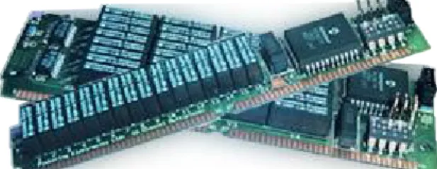
There is often a need for a small relays-system, standalone or when adding to an existing system. Until now the test system developers at Enics have been using Pickering's SIMRC (as seen in figure 1) modules or made their own devices with prototyping boards and additional electronics (figure 2).
There are huge disadvantages with both these options. The SIMRC modules are relatively expensive, difficult to mount, have a fragile communication interface with a small weak jack and leads and they also need external 5V power supply.
When making a device, e.g. for parallel port control, by using a prototyping board, relay drive circuitry, connectors and communication interface etc. the biggest disadvantage is that it takes a lot of time to build. It also won't get sturdy, it looks bad and it may end up doing unintentional things while starting the interfacing computer.
Initially the final target was very open and different topologies were considered. One of the main parts of the work was to investigate what would be the best solution for different kind of tasks where relays are used.
The original objective was to make a modular system which could be assembled differently depending on the actual, specific, purpose. It should be able to work as a small standalone system as a cost effective alternative where larger chassis can't be justified. It should also be a good complementary system for existing test systems and/or fixtures where the primary switching resources are insufficient. When there is a need for controllable relays it should be easy and quick to get a circuit board and assemble it with suitable components such as preferred relays, connectors and communication interface.
1.3 Problem formulation
The problem to be solved is to examine which solution(s) is best suited to solve the needs and demands as stated in the objective. The task is to design a modular system for controlling relays. The design of a circuit board with a communication interface and intelligence for controlling relays is not itself difficult; a big part of the problem is to find and chose a design that fulfils the needs appropriate.
1.4 Limitations
● MODULAR The system has to be modular. Either there should be some
different purpose-dependent devices or there should be one flexible device, with the option to mount different components depending on the current demands.
● COST The price should be as low as possible aiming for less than
100 SEK for PCB+components, relays not included. Figure 2 Simple relay system
● ROBUST The card should have holes for mounting with distance bolts. All connectors need to be sturdy.
● FLEXIBLE Different systems demands different solutions regarding
connectors so alternative mounting should make it possible to mount jacks, wire wrap connectors or screw terminals.
● POWER SUPPLY If possible the device(s) should not require external power
supply and/or use the same power supply for the control circuit and the relays.
● COMMUNICATION The communication protocol should be designed so that the
PC's plug and play process won't switch relays.
If the solution is based on a microcontroller, FPGA, CPLD or similar; appropriate firmware should be developed. When the system architecture is chosen it should be prototyped and tested. The circuit board should be sufficiently documented with an explicit BOM, simplifying the process of ordering materials for assembly. The task also includes defining communication protocol(s) used for controlling the relays.
Chapter 2
METHODS
This chapter describes the process of defining the final product. Different rejected suggestions are also shortly described.
2.1 Concept proposals
Since it was initially unclear how the final switching system should be designed, a number of different suggestions where made and then discussed with the engineers at Enics to determine what would be the best concept for them.
One thing that was clear from the beginning was that a different amount of relays would be suitable for solving different kind of problems. Sometimes eight or less relays are suitable, and sometimes the demand is for 20-30 relays. The main system controlling the relays are most likely to be some kind of a PC with some sort of communications interface, a parallel and/or a serial port but sometimes only USB is available (for example on newer laptops). Since it is unlikely that the controlling system have for example multiple serial ports it was a requirement that multiple devices could be controlled from one communication interface. Two major concepts where proposed.
One concept was that all cards should be identical, with optional mounting of components. In this case all devices would locally act as master-units, controlling the relays on the actual device.
Within this concept it could be possible to do it in two different ways. The device connected directly to the PC could connect further devices parallel(1a) or further devices could be connected in a daisy-chain(1b).
Booth these options have advantages and disadvantages.
In 1.a) the PCBs for the devices have to be prepared with the same amount of connectors as the possible amount of devices connected to it; however programming the communications interface could be made easier when dealing with a pre-known number of devices.
In 1.b) the devices would have one communications interface to the controlling system and one communications interface to the next device (controlled by the controlling system through this actual device). Only two connectors are needed on each PCB for this purpose; however in this case the firmware needs to be more complex since all devices should act equally regardless of where they are connected in the daisy-chain.
The second concept was the use of a number of different devices, one device acting as an intelligent master-unit only. This master-unit would have a communications interface and this device would then handle the actual controlling of relays. In addition to this master unit there would be one or many slave-units including the relays interface (drivers and connectors). The slave-unit(s) could be one flexible device with the ability to mount different kind of relays, or a number of different devices depending on what relays and currents/voltages it should handle. Slave-units could be connected to the master-unit either in parallel(2a) or in a daisy-chain(2b), perhaps with built on shift-registers for interfacing of relays.
Figure 3: Concept 1.a)
One unit is connected to the PC on the other units are connected in parallel to that device.
PC RELAY DEVICE RELAY DEVICE
RELAY DEVICE
1.a)
Figure 4: Concept 1.b)
All devices are connected in a daisy-chain.
PC RELAY DEVICE RELAY DEVICE
1.b)
Figure 5: Concept 2.a)
One intelligent master-unit is connected to the PC and slave-units with only relays and drivers are connected in parallel to the master-unit.
PC MASTER SLAVE SLAVE
SLAVE
Concept 1.b) was selected, because of its flexibility. If all devices are identical, except for what relays and communication interface is chosen, it makes it easier to build relay systems. The only thing optional is what kind of relays to use and this is usually already decided depending on the purpose for the system. It is also cheaper to buy many identical PCB's than many different so this concept makes overall cost more inexpensive. Concept 1.a) was rejected in favour of 1.b) because the systems that would be built within concept 1.b) are easier to build to and have simpler PCBs with the only disadvantage being the development of the FW for the intelligence on the devices.
It was specified that each device should be able to be mounted with up to eight relays.
Further decisions were established during this phase of the project: The PCB should be single or dual layer with dimensions 100x160mm which is a standard size for PCB's and as many components as possible should be through hole mounted for easier assembly.
The device was going to be named E-REX – “Enics – Relays EXamensarbete” (Swedish for degree project).
2.2 Power supply
The aim was that the device should work without external supply and instead be powered from a computer. Therefore the available options to power external devices from the computer was investigated. The USB-port can supply 100mA at 5V and up to 500mA at 5V if requested for. The system is designed for 1A, although only about 700-800mA is the normal maximum current usage when all relays are energized. 100mA is too little for this application and to get 500mA a dedicated USB-system had to be designed, still supplying slightly less current than wanted. So the system was specified to use an external power supply. Since the relay-control system is used in different environments it was specified to work with an input voltage ranging from 5-24V.
2.3 Intelligence
To be able to communicate with the devices, and to be able to control the relays from the PC with simple commands, intelligence is needed. It could be done using the parallel port and simply using a shift register or similar, but it is not safe for noise on the communication line between devices and the PC and it would also need a more complex/higher-level program on the PC.
Figure 6: Concept 2.b)
One intelligent master-unit is connected to the PC and the slave-units with only relays and drivers (and shift-registers) are connected in a daisy chain to the master-unit.
PC MASTER SLAVE SLAVE
The most obvious alternatives are FPGA/CPLD or microcontrollers. Programmable logic are more complex to develop firmware for, so that option was rejected. There are a wide variety of microcontrollers on the market, the most popular being Atmel AVR and Microchip PIC. Pontus Klarsjö, one of Enics test engineers had previous experience with AVR's so that was the choice for this project.
There are up to eight relays on each device. To be able to communicate with the controlling device and with other devices two UARTs are used. The UARTs uses two I/O pins each, one for receiving and one for transmitting. So at least 12 dedicated I/O-pins was needed. At first the ATtiny 2313 was selected, before the final product was designed, for its low cost. Some time after that decision the microcontroller was changed to the Atmega48. The Atmega48 have more flash-memory to store FW on which later on, during FW-development, turned out to be an essential need. In addition it has six analogue inputs, which could be used for example for detecting when a test fixture is closed and ready for testing.
2.4 Communication
The system that should be designed should be very flexible, and one of the requirements was that it should have a various of different interfaces for communication and for controlling the relays. The most obvious communication interfaces on computers are the serial port and the parallel port. The serial port hooks up easily to a microcontroller through an RS-232/TTL converter to the microcontroller's UART. A lot of time was spent trying to find a suitable interface for connecting the parallel port to the AVR, but nothing satisfactory was found. The parallel port connector has another disadvantage which is the size of the connector, it uses a 25 pin connector which would take up a considerable amount of space on the PCB and it was not likely to be used very often in the applications for the device. Because of this the possible parallel port interface was rejected. Instead other options was considered. The UB232R module was found from ELFA's assortment. The UB232R is a USB to TTL converter which turns the USB-port into a virtual serial port. Footprint for this was added on the PCB directly connected to the UART on the AVR. The same footprint could be used when designing a future converter module for other communication interfaces.
2.5 Connectors
The connectors on the device had to be very sturdy and robust to avoid situations where cables unintentionally detach, but at the same time it should be possible to use some different kinds of connectors depending on usage. Some products that Enics manufacture for Bombardier use Phoenix/Wago connectors, which are very sturdy and the connectors snap on to the headers.
Phoenix headers are used for the connections to the relays and for the power supply, the most crucial connections. The distance between the leads on the Phoenix connectors is 5.00mm and the same mounting holes can be used to mount wire wrap connectors or screw terminals. Other types of connectors can be mounted as well.
The RS-232 communication interface use 9 pole D-SUB connectors.
Communication between devices are connected with ribbon cables attached to four-pole pin headers with a lead distance of 2.54mm. The interface for controlling the relays manually (described in Chapter 3) and for the analogue inputs to the AVR are also done through the same kind of standard pin headers.
2.6 Designing the PCB
The electronic schematic and PCB-layout was done using CadSoft EAGLE. The PCB was designed as dual layer on an area of 100x160mm2.
The most difficult section to route was the connections between the relays and the connectors. The ambitions for these traces was to get balance between good current handling and good clearance distances (for switching higher voltage signals). It would be good to be able to switch 230V AC-signals (EU-standard wall voltage), but only if possible to implement.
Two proposals were made. Suggestion no.1 allows for slightly higher currents, about 2.6A on 35µm copper (calculated with PCB-Trace width calculator, see “references”) when allowing a temperature rise of 20°C. Suggestion no.2 would allow currents of 1.4A during the same conditions with the advantage of single-sided design allowing for easier prototyping.
Suggestion no.2 was picked, party because it could be done on a single-sided PCB. It is convenient to be able to prototype the whole device on a single-sided PCB. In the final product the traces from the relays to the connectors are simply doubled on both sides for added current abilities, in theory it should be doubled to allow for 2.8A.
Spacing between conductors are 0.6mm at the smallest distance, which would allow for voltage insulation somewhere near 300V, but this has to be tested in a practical situation for verification. (See appendix C. - “PCB-Insulation table”.)
For the same reason as single sided traces was preferred as an option for the relays and connectors, to be able to prototype a single sided PCB, the surface mounted voltage regulator and PFET circuits are placed on the bottom layer.
To be able to complete the full circuit more signals had to be placed on the top layer, so to be able to make a working single-sided device a number of jumpers would have to be used, but it is possible to do. Even though going for a double sided layout the layout with surface mount components on the bottom layer remained.
The first revision of the PCB was prototyped at MDH using the available PCB-milling machine. The first idea of making it a single sided prototype was rejected in favour of a dual-layer layout because it would have been a mess of jumper wires on the completed definitive layout. When the first prototypes were assembled it was noticed that one connection for the communications was wrong, this was fixed and a new prototype was made that worked.
Figure 7: Routing
worked good but one problem was detected when FW was further developed, so one resistor was added in addition to the regular components according to the CAD.
2.7 Programming the FW
The programming of the FW was done using the C-programming language, with libraries for the AVR microcontroller. The programming was done in AVR Studio which incorporates AVR-GCC for C-programming.
The FW is written as almost any kind of C-program and compiled and linked together with AVR Studio. The specific settings for the Atmega48 are taken care of by built in libraries in the AVR Studio program, set up in the project options. The output from this program is a hex file with machine code for the microcontroller.
To download the FW to the AVR another program, PonyProg, is used to interface the serial programmer built on the E-REX device (described in chapter 3). With this program the hex file is transmitted to the AVR. PonyProg is the tool to set fuse-bits for controlling the frequency of the AVR's clock. For the E-REX device the settings in PonyProg should be according to these pictures.
The settings in the pictures should be done immediately after starting PonyProg. Then the configuration and security bits should be set. Then the EEPROM and FLASH can be downloaded in any order.
Sometimes it happens that PonyProg won't find the target-circuit(the AVR) when trying to download FW to it, then in some cases it can be made possible to do this anyway by shorting the AVR's reset-pin (pin 1 on the Atmega48) to ØV during programming.
Figure 10: Configuration and security bits
Figure 12: I/O port setup
Figure 11: Program
2.8 Cost
The cost of the device is quite a lot more than the target of less than 100 SEK excluding relays. The price for the PCBs was 250 SEK/a piece, when ordering an amount of ten, and the components (excluding the relays) cost approximately 180 SEK. This could be less if ordered in higher quantities but the focus during the development of the E-REX devices was mainly on function rather than cost; but of course the cheapest, yet functionally satisfying, components were chosen.
Chapter 3
FUNCTIONAL DESCRIPTION
Following in this chapter is a detailed description of the purpose and function of each part of both hardware and the firmware code for the microcontroller.
3.1 Hardware
The hardware consists of the electronics circuitry for the relays controlling device and the mechanical layout of the PCB and the device as a whole.
Power Supply
The device was specified to be able to work with input voltages ranging from 5 to 24 V. It was decided that the relays should run on 5V and use the same supply as the control circuitry. The Tyco RT424005 relays have a coil resistance of 62Ω ± 10% thus giving a minimum coil resistance of 62 - 6.2 = 55.8Ω. Driven by 5V each relay sinks 5V/55.8Ω ≈ 90mA from the power supply. The device can be mounted with up to 8 relays, and if all would be energized simultaneously they would sink 8x90mA = 720mA. If the device would be utilizing a linear
Figure 13: Block diagram
AVR (WITH FIRMWARE) RELAYS DRIVER POWER SUPPLY 5-24V -> 5V MANUAL CONTROL THROUGH CONNECTOR ANALOGUE INPUTS COM. INTERFACE FOR CONTROLLING THIS DEVICE COM. INTERFACE FOR COM. WITH OTHER DEVICES
supporting 720mA of 5V, with an input of 24V, would dissipate (24-5)*0.72 ≈ 14W. Another disadvantage of a linear regulator is that it has a voltage drop, usually in the magnitude of a couple of volts, this is unacceptable since circuit should work with and input of 5V while still having an output of 5V. Because of this a switch-mode power supply integrated circuit with the ability to run with 100% duty cycle, allowing for the same output voltage as input, was settled for.
The power supply is based around the National Semiconductor's simple switcher LM3485. The design used is fully based around the typical application from the data sheet, adapted to 5V out instead of 3.3V that was used in the data sheet.
The LM3485 is a hysteretic high efficiency PFET, buck switching regulator. It switches the input voltage via an external PFET through an inductor. The output voltage is then measured on the feedback-pin at the junction of R10 and R11. The regulator keeps the voltage at the feedback-pin at 1.242V (typically) with an hysteresis voltage of 10mV. When the voltage at the feedback-pin falls below this value the PFET is turned on, and when the voltage is above this the PFET is turned off. This enables the regulator to work at a lower frequency during light loads and at higher frequency as the load increases. This also allow for the same output voltage as the input voltage, keeping the PFET always on during this state.
The criteria for choosing the P-channel MOSFET was, according to the LM3485 data sheet, sufficient maximum drain-source voltage (to withstand Vin-Vout during the off-state), low
RDSON(to minimize power loss in the PFET), current rating and input capacitance(to minimize
switching losses). Also to ensure that the PFET turn on quickly enough, and completely, during different input voltages a low-threshold PFET should be used. Furthermore the turn-on rise time should be no more than 100ns to ensure efficiency in the voltage regulator. According to the data sheet the input capacitance should be kept less than 2000pF. With these parameters limiting the selection IRF7416 was chosen.
When choosing the inductor the important parameters are the current rating and the inductance, although a wide range of inductance values can be used. An inductor with an inductance of 100µH and a current rating of 1.1A is used in this application.
Output voltage is programmed with R10 and R11 since Vfb is kept at 1.242V: Vout =
1.242*(R10+R11)/R11. In this application R10 is 53k6Ω and R11 18k which gives a Vout of
4,94V. The resistors was chosen to get a value as close as but still below 5V.
The regulator has built in cycle-by-cycle current limit, which is adjusted by R12 according to the formula from the data sheet: Radj = IIND_PEAK * RDSON/ICL_ADJ. In this application Radj = R12.
IIND_PEAK= ILOAD + IRIPPLE/2. ILOAD was set to 1A in this application, and IRIPPLE is calculated with
the formula from inductor selection: Δi ≤ IOUT * 0.386827 * IOUT-0.366726. With an IOUT of 1A this
gives a ripple of less than 0.193412V. RDSON for the chosen PFET is typically 0.02Ω.
According to the data sheet for the LM3485, using the minimum value for ICL_ADJ of 3.0µA
ensures that the current limit threshold will be set higher than the peak inductor current. With these values Radj is calculated to be 7656.08Ω and so a value for the resistor was chosen
to be 8.06kΩ.
Computing
The microcomputer was chosen based on the demands for enough I/O-pins and the need for some A/D-inputs, it was also wanted the microcomputer should have a built in oscillator to limit the needs for external components, but the biggest issue was to find the cheapest possible microcomputer that still satisfies the peripheral needs. Both Microchip PIC and Atmel AVR have suitable products with similar prices. AVR was chosen simply because of the fact that one of the mentors at Enics had previous experience of those. As most or all parts should be able to be bought from ELFA, different suggestions was compared from their range of products. The Atmel ATMEGA 48 was one of the cheapest and with up to 23 I/O-pins and 4kB of FLASH memory; it was good enough and not beyond what was needed.
Communications and programming interface
Communication to the AVR can be done with some different serial protocols. The PCB is prepared for an RS232/TTL converter (MAX202CPE), but it could also be done directly with TTL if that is available. The MAX202 IC is connected according to the typical operating circuit according to the data sheet.
Using TTL levels directly to the AVR's UART is also how communication is done between E-REX devices. As explained in the firmware section later on; a device sees no difference whether it is connected to a PC or another E-REX.
Each device have two UART's, one which is hardware implemented in the AVR's architecture and one software implemented in firmware on two general I/O-pins on the AVR. The HW-UART is connected upstream; to a controlling device e.g. a PC or to an another, controlling, REX. The SW-UART is connected downstream to the adjacent REX device. If multiple E-REX devices are used in the same application they are connected in a daisy-chain and communication is done from the PC (or whatever is used) to all devices through the first. In addition the PCB's are prepared for adding an UB232R module for serial communication from a PC's USB-port. Another module with the same footprint as the USB-module have been found which allows for Bluetooth communication if that is desired and of course any custom module could be built for future methods of communication.
Both the RX(receiving) and TX(transmitting) pins of the HW- and SW-UART have LED's connected on them for visual inspection of communications; which, among other things, helps during troubleshooting.
During normal communication on the the UART, the transmitting line is kept at a digital '1' (5V in this application) until something is transmitted. This is used in the firmware for detecting if the actual card is the last one in the daisy-chain or if another device is connected to the SW-UART. The I/O-pins on the AVR have internal pull-up resistors, this means that if nothing is connected to an input it is considered a digital '1'. Therefore, to be able to detect if another device is connected a pull-down resistor had to be added. Since there also are LED's connected to all the communication lines this value has to be calculated accordingly to make sure it will be interpreted as '0'.
The above picture shows how this was done. The label “SW-UART” shows where the AVR's receiving pin are connected, the same place as the possible next device's transmit PIN is connected. If a transmitter (another E-REX device) is connected to the SW-UART-line it have full control, but if left floating a voltage divider is made from R1-LED1 and R2. According to the data sheet for the AVR, the maximum voltage on an input-pin for it to be interpreted as '0' is 0.3VCC when VCC is 5V as used in this application. So the voltage drop over R2 needs to
be less than 0.3*5V = 1.5V. LED1 is a red LED and has a voltage drop of approximately 2V and the voltage drop over R2 should be at most 1.5V. The same current flows through R1, LED1 and R2 so the minimum current is calculated by dividing (5-2-1.5) by 1000 (R1) = 15mA. 1.5V/0.0015A = 1000Ω is the maximum value for R2 and 330Ω was chosen for safety margin. When a transmitting device is connected and set as '1' it will source 5V/330Ω ≈ 15mA, this is no worry since the pins on the AVR are specified for a maximum current of 40mA.
Programming of the device was specified to be possibly by using a serial cable only, without the need for an external programming device. Thus a very simple programming interface was found and implemented on the PCB. It was found online, made by an electronics hobbyist. It consists only of four resistors, one BJT and two zener diodes, and it works satisfying.
Figure 15: Software-UART connections
Figure 16: Displays how devices are connected together
PC E-REX E-REX E-REX HW-UART SW-UART
Figure 17: Programming interface schematic
When downloading FW to the device a jumper is connected to allow for the AVR's reset-pin to be controlled by the PC's programming software through the serial port. This jumper was added in addition to the original schematic, in between the BJT and the reset-pin on the AVR. When the device is in use, and not being programmed, the jumper is left open.
Relays and driver
The PCB layout enables for optional mounting of three different types of footprints for relays, the Pickering relays being used have two different types of pin-dimensions and then there is the Tyco relays with another pin-dimension. These three different footprints are connected in parallel on the PCB. The PCB layout is designed so the connectors and the Tyco DPDT relays match. The connectors are three rows and two columns of 8-pole Phoenix-connectors (other kinds of connectors could be mounted). It is designed so the top row are connected to the relays NO-pins, the middle row to the C-pins and bottom row are dedicated to the NC-pins.
The traces from the relays to the connectors are duplicated on both the primary (top) and the secondary (bottom) side of the PCB for enhanced current capability.
In parallel to the relay coils there are LED's with current limitation resistor for visual indication of which relays are closed.
The driver for the relays is an ULN2803 which is a widely used 8channel high-voltage, high current darlington driver array with built in clamping-diodes. The relays are controlled through the driver, either from the AVR by commands through the communication interface, or directly from the SV5 connector. If the relays are to be controlled from the connector manually or from an external controlling device (through the SV5 connector) the AVR should not be mounted, otherwise the I/O-pins will be damaged.
3.2 Firmware
The firmware for the AVR microcontroller is written entirely in the C-programming language. It is divided in eight c code files connected together with seven header files:
MRC.c - Contains the main program.
ad.c/h - Contains functions for the A/D inputs.
getarg.c/h - Contains functions for extraction of arguments from
commands.
process.c/h - Contains functions for processing of received
commands.
process_sUART.c/h - Contains functions for processing commands from and
to the next device connected to the SW-UART.
softuart.c/h - Contains an implementation of an extra UART using
two general I/O-pins for receiving and transmitting data. These functions are borrowed from Colin Gittins who wrote the original generic code, and Martin
Thomas who adopted the code for use on AVR. It was slightly modified by me for use on the Atmega48.
timeout.c/h - Contains functions for a timer interrupt routine used
when communicating to further devices in order to get timeout errors if a device won't answer.
uart.c/h - Contains functions for communication on the
HW-UART.
This subchapter will not explain the complete code but describe it on a higher level using flowcharts and text. The complete source code can be seen in the appendix.
Figure 19: Program flow POWER ON RESET REGISTERS INITIATE PERIPHERALS READ HW-UART VALID COMMAND? PROCESS COMMAND NO YES
Power-on
When an E-REX device is powered the AVR starts with resetting the registers i.e. ports are set to input/output and outputs are set to '0'. It then initiate peripherals, the A/D and the HW-UART. Finally received strings on the HW-UART are interpreted and processed.
Valid commands
● INIT - Initiate devices. Replies with “INIT OK <n>”, where <n> is the number of initiated devices, or with an error string. At the same time all relay outputs are set to '0'.
● RC <d> <r> - Close relay <r> on device <d>. Reply is “OK” or an error string. ● RO <d> <r> - Open relay <r> on device <d>. Reply is “OK” or an error string. ● RS <d> - Read relay status on device <d>. Reply is “RS <d> Øx<hex>
Øb<bin>”, showing the status of each relay on the device. ● AI <d> <a> - Read analogue input <a> on device <d>. Reply is “AI <d> <a>
<hex>”, with the analogue value printed in hexadecimal.
● ? - Print list of available commands.
Error codes
● “UNKNOWN COMMAND” - If the received command doesn't match any of
the valid commands.
● “INIT ERROR TIMEOUT <d>” - If device <d-1> get no reply from device <d>, during initialization, it sends a timeout error- message to the preceding device.
● “ERROR TIMEOUT <d>” - If device <d-1> get no reply from device <d>, after passing a command, it sends a timeout error-message to the preceding device.
● “ERROR CORRUPT <d>” - If device <d-1> get a non valid reply from device <d> it sends this error-message to the preceding device.
● “NO SUCH DEVICE” - If for instance “RC 3 4” is received and device 3
is uninitialized.
● “NO SUCH RELAY” - If the received relay-argument is less than 1 or
more than 8.
● “NO SUCH CHANNEL” - If the received analogue input-argument is less
than 1 or more than 6.
Initialization
When an E-REX device is powered, and before “INIT” is passed as command to it, only the first device is controllable. In order to be able to use multiple devices the devices have to be initiated. This should also be done when only one unit is used, to ensure that all relays are initially open.
When “INIT” is sent to the first device it reads the SW-UART's receive pin. If there is another device connected to the first device, the first device's receive pin is '1' due to the UART-interface. If another device is detected then “INIT <n+1>” is sent to the next device (for the first device in the chain n+1 would equal to “1”). The number passed(<n+1>) is to make sure that if there is a nonresponsive device then the last live unit should be the one sending an
If no other device is detected the unit replies with “INIT OK 1”. If “INIT OK <n>” is detected on the SW-UART the string “INIT OK <n+1>” is sent to the HW-UART.
When receiving the “INIT OK <n>” each device stores <n> in its RAM. This is used when processing commands to make sure that the command is valid, if there are no such device the appropriate error-message “NO SUCH DEVICE” is sent.
Intercommunication
Each E-REX device consider themselves as the first unit in the chain and they don't care about how many devices are connected between themselves and the PC. Commands passed between devices are done in the same way as they are expected to be received from a controlling device (typically a PC).
For instance when the command “RC 3 1” is passed to the first device, unit 1 first and foremost validates the command and if it is a valid command it extracts the device-argument. If the device argument is “1” it processes the command on the actual device, otherwise it passes the same command but with device-argument = <d-1> to the next device. The device that receives command “RC 1 1” closes relay 1 and replies with an “OK”, the OK is then passed backwards through the chain.
Timeout handling
When a command is sent to a further device a timer starts and the device waits for a response from the next device. If there is no reply before the timer runs out an error-message is sent. Each device knows how many devices are connected further to ensure that the furthermost live unit replies the error-message.
Figure 20: Initialization
PC INIT E-REX INIT 1 E-REX INIT 2 E-REX
INIT OK 1 INIT OK 2
INIT OK 3
Figure 21: Intercommunication between devices
PC RC 3 1 E-REX RC 2 1 E-REX RC 1 1 E-REX
OK OK
OK
PC RS 3 E-REX RS 2 E-REX RS 3 E-REX
X TIMEOUT
ERROR TIMEOUT 2 ERROR TIMEOUT 3
Help text
If the command “?” is passed to a device it responds with the available commands. Because the flash memory got full this text is placed as a string in the EEPROM which is specifically written to EEPROM using PonyProg.
SW-UART
The software implemented UART code is borrowed from a code written by Colin Gittins as a generic code and adapted to AVR by Martin Thomas. It uses 2 general I/O-pins and one system timer for the reception and transmission. The SW-UART library by Martin Thomas can be found at: http://www.siwawi.arubi.uni-kl.de/avr_projects/#softuart
The settings for the system timer used was adapted for the Atmega48 and a simple function for receiving a string for communication between the devices was developed.
Chapter 4
CONCLUSIONS
This thesis, and all the practical work within it, have covered the complete manufacturing process of an electronic device. Ranging from analysis of different solutions through design, construction and programming to preparing PCB-files for ordering and finally producing the product including documentation for assembly and downloading of FW etcetera. Because of that it have been a great experience in electronics development, but unfortunately it also took a great amount of time. During the first two months (which under normal circumstances should have been the complete time for the actual project) most of the time was dedicated to investigate, in interaction with the engineers at Enics, and narrow down what the final resulting product should actually be. A lot of time have also been spent dealing with small, relatively according to the final product, issues and problems occurred during development. The target-price for the product was, in a very early stage, aimed for less than 100SEK for the PCB and components excluding relays. The components themselves cost around this much, depending on how which components is assembled on the specific device, and the PCB's costed 250SEK each when ten pieces were ordered. This was accepted to be able to fulfil the higher priority demands of function and flexibility. The cost could probably be much cheaper if a larger amount of devices should be produces, and if components is ordered together with components already on products manufactured by Enics.
Even though the project took (much)more time than expected we all(me and the engineers/advisor's at Enics) agree that the final product is very flexible and adapted to its purpose. Even before the FW was fully completed, for interaction between multiple E-REX devices, E-REX devices was in use both at Enics Västerås and at Enics location in Nova Dubnica, Slovakia.
Chapter 5
FUTURE WORK
There are some improvements that have to be on both HW and SW, described more precisely in this chapter.
5.1 HW
The PCB-prototypes was ordered before the FW was fully developed. Because of this some issues with the construction was found during the FW-development.
The SW-UART communication used between devices uses the fact that the transmitter-pin on the connected device is '1'. This clever idea came after the PCB's were ordered. Initially the idea was to initiate devices presuming that there is a device connected and otherwise if a timeout is detected taking that as the actual device is the last in the daisy-chain. Because of this the pull-down resistor, making sure that the last device reads a '0' on this pin, is not on the first revision of the PCB. This resistor is patched to the products in use and should be added to the CAD-files for future orders.
Another hardware issue that was found was that units that are connected together with the ribbon-cable for communication, but without an own primary power supply, gets powered through the inputs on the AVR and actually works (although randomly). All devices should be connected to the power supply and be fully functional. If the power supply connection is lost to one unit this has to be detected somehow by the preceding so the user can troubleshoot the issue. This problem originate from the fact that the AVR have built-in pull-up resistors on its inputs. By connecting resistors in series with the communication lines this phenomenon can be avoided. The resistors should be dimensioned to ensure that communication still works at the same time as a device is kept shut off unless connected to a power supply.
One more issue concerning the communications interface is that if the standard protocol for serial port communication is used and a device is powered, it will switch relays on and off because of the programming interface using the same AVR ports as the relay driver. This can be prevented by changing the serial port function for hardware handshaking in software, but a better solution would be to change the layout for the signals between the AVR and the relay driver.
The connections between the relays and the connectors are theoretically calculated to handle 2.8A and to insulate up to a maximum of 300V. This has to be tested in a practical situation to see how it works, the devices may be able to perform better than this, or worse. This may of course also be limited below this depending on which relays are being used. The current capacity can be widely enhanced by adding wires in addition to the PCB-traces between the connectors and the relays.
5.2 FW
The command handling features of the FW for the devices are not foolproof. For example if the command “RS 3<junk>” is passed to a device it is interpreted the same as “RS 3” (read relay status on device 3). This should be improved to avoid errors, and to be able to detect problems in the controlling systems communication interface.
During development of the FW a lot of optimization had to be done because of the Atmega48 flash-memory limit of 4kB. The current FW use about 98% of that. To be able to get more functionality into the devices it is possible to change the microcontroller to an Atmega88 which is identical to the Atmega48 but with the double amount of available memory.
Chapter 6
REFERENCES
Enics Sweden AB:
http://www.enics.com [2008-04-03] Wikipedia:
http://www.wikipedia.org [2008-04-28] Atmega48 data sheet:
http://www.atmel.com/dyn/resources/prod_documents/doc2545.pdf [2008-05-16] AVR Studio:
http://www.atmel.com/dyn/products/tools_card.asp?tool_id=2725 [2008-06-09] PonyProg:
http://www.lancos.com/prog.html [2008-06-28] MAX202 data sheet:
http://datasheets.maxim-ic.com/en/ds/MAX200-MAX213.pdf [2008-06-27] LM3485 data sheet:
http://www.national.com/ds/LM/LM3485.pdf [2008-06-28] IRF7416 data sheet:
http://www.irf.com/product-info/datasheets/data/irf7416.pdf [2008-07-14] UB232R data sheet:
http://www.ftdichip.com/Documents/DataSheets/Modules/DS_UB232R.pdf [2008-09-15] PCB trace width calculator:
http://www.circuitcalculator.com/wordpress/2006/01/31/pcb-trace-width-calculator/ [2008-05-16]
Martin Thomas SW-UART-library:
http://www.siwawi.arubi.uni-kl.de/avr_projects/#softuart [2009-05-11] ELFA: