Mälardalen University Press Dissertations
No. 98
NUMERICAL ANALYSIS OF HEAT TRANSFER AND FLUID FLOW IN
HEAT EXCHANGERS WITH EMPHASIS ON PIN FIN TECHNOLOGY
Hamid Nabati
2012
Mälardalen University Press Dissertations
No. 98
NUMERICAL ANALYSIS OF HEAT TRANSFER AND FLUID FLOW IN
HEAT EXCHANGERS WITH EMPHASIS ON PIN FIN TECHNOLOGY
Hamid Nabati
2012
Copyright © Hamid Nabati, 2012
ISBN 978-91-7485-062-8
ISSN 1651-4238
Mälardalen University Press Dissertations
No. 98
NUMERICAL ANALYSIS OF HEAT TRANSFER AND FLUID FLOW IN
HEAT EXCHANGERS WITH EMPHASIS ON PIN FIN TECHNOLOGY
Hamid Nabati
Akademisk avhandling
som för avläggande av teknologie doktorsexamen i energi- och miljöteknik
vid Akademin för hållbar samhälls- och teknikutveckling kommer att
offentligen försvaras fredagen den 13 april 2012, 10.00 i Delta, Västerås.
Fakultetsopponent: professon Dan Loyd, Linköping University
Mälardalen University Press Dissertations No. 98
NUMERICAL ANALYSIS OF HEAT TRANSFER AND FLUID FLOW IN HEAT EXCHANGERS WITH EMPHASIS ON PIN FIN TECHNOLOGY
Hamid Nabati
Akademisk avhandling
som för avläggande av teknologie doktorsexamen i energi- och miljöteknik vid Akademin för hållbar samhälls- och teknikutveckling kommer att offentligen försvaras fredagen den 13 april 2012, 10.00 i Delta, Västerås.
Fakultetsopponent: professon Dan Loyd, Linköping University
Abstract
One of the most important industrial processes is heat transfer, carried out by heat exchangers in single and multiphase flow applications. Despite the existence of well-developed theoretical models for different heat transfer mechanisms, the expanding need for industrial applications requiring the design and optimization of heat exchangers, has created a solid demand for experimental work and effort. This thesis concerns the use of numerical approaches to analyze and optimize heat transfer and fluid flow in power generation industry, with emphasis on pin fin technology.
This research begins with a review on heat transfer characteristics in surfaces with pin fins. Different pin fins shapes with various flow boundaries were studied, and thermal and hydraulic performances were investigated. The impact of parameters such as inlet boundary conditions, pin fin shapes, and duct cross-section characteristics on both flow and heat transfer were examined. Two important applications in power generation industry were considered for this study: power transformer cooling, and condenser for CO2 capturing application in oxy-fuel power plants. Available experimental data and correlations in the literature have been used for models validation. For each case, a model based on current configuration was built and verified, and was then used for optimization and new design suggestions. All numerical modeling was performed using commercial CFD software. A basic condenser design was suggested and examined, supplemented by the use of pin fin technology to influence the condensation rate of water vapour from a CO2/H2O flue gas flow. Moreover an extensive review of numerical modeling approaches concerning this condensation issue was conducted and presented.
The analysis results show that the drop-shaped pin fin configuration has heat transfer rates approximating those of the circular pin configuration, and the drop-shaped pressure losses are less than one third those of the circular. Results for the power transformer cooling system show those geometrical defects in the existing system are easily found using modeling. Also, it was found that the installation of pin fins in an internal cooling passage can have the same effect as doubling the radiator’s height, which means a more compact cooling system could be designed.
Results show that a condensation model based on boundary layer theory gives a close value to experimental correlations. Considering a constant wall temperature, any increase in CO2 concentration results in lower heat transfer coefficients. This is a subsequence of increased diffusivity resistance between combustion gas and condensing boundary layer. Also it was shown that sensitivity of heat transfer rate to inlet temperatures and velocity values decreased when these parameters increased. The application of numerical methods concerning the condensation process for CO2 capturing required significant effort and running time as the complexity of multiphase flow was involved. Also data validation for the CO2/H2O condenser was challenging since this is quite a new application and less experimental data (and theoretical correlations) exist. However, it is shown that models based on numerical approaches are capable of predicting trends in the condensation process as well as the effect of the non-condensable CO2 presence in the flue gas.
The resulting data, conclusions, applied methodology can be applied to the design and optimization of similar industrial heat exchangers, such as oil coolers which are currently working at low efficiency levels. It can also be used in the design of electronic components, cooling of turbine blades, or in other design applications requiring high heat flux dissipation. Finally, the finding on water vapour condensation from a binary mixture gas can be referenced for further research and development in this field.
"Education is a progressive discovery of our own ignorance."
Abstract
One of the most important industrial processes is heat transfer, carried out by heat exchangers in single and multiphase flow applications. Despite the existence of well-developed theoretical models for dif-ferent heat transfer mechanisms, the expanding need for industrial applications requiring the design and optimization of heat exchangers, has created a solid demand for experimental work and effort. This thesis concerns the use of numerical approaches to analyze and optimize heat transfer and fluid flow in power generation industry, with emphasis on pin fin technology.
This research begins with a review on heat transfer characteristics in surfaces with pin fins. Different pin fins shapes with various flow boundaries were studied, and thermal and hydraulic performances were investigated. The impact of parameters such as inlet boundary conditions, pin fin shapes, and duct cross-section characteristics on both flow and heat transfer were examined. Two important appli-cations in power generation industry were considered for this study: power transformer cooling, and condenser for CO2 capturing application in oxy-fuel power plants. Available experimental data and
correlations in the literature have been used for models validation. For each case, a model based on current configuration was built and verified, and was then used for optimization and new design sug-gestions. All numerical modeling was performed using commercial CFD software. A basic condenser design was suggested and examined, supplemented by the use of pin fin technology to influence the condensation rate of water vapour from a CO2/H2O flue gas flow. Moreover an extensive review of
numerical modeling approaches concerning this condensation issue was conducted and presented. The analysis results show that the drop-shaped pin fin configuration has heat transfer rates approxi-mating those of the circular pin configuration, and the drop-shaped pressure losses are less than one third those of the circular. Results for the power transformer cooling system show those geometrical defects in the existing system are easily found using modeling. Also, it was found that the installation of pin fins in an internal cooling passage can have the same effect as doubling the radiator’s height, which means a more compact cooling system could be designed.
Results show that a condensation model based on boundary layer theory gives a close value to experi-mental correlations. Considering a constant wall temperature, any increase in CO2 concentration
re-sults in lower heat transfer coefficients. This is a subsequence of increased diffusivity resistance be-tween combustion gas and condensing boundary layer. Also it was shown that sensitivity of heat trans-fer rate to inlet temperatures and velocity values decreased when these parameters increased. The application of numerical methods concerning the condensation process for CO2 capturing required
significant effort and running time as the complexity of multiphase flow was involved. Also data vali-dation for the CO2/H2O condenser was challenging since this is quite a new application and less
exper-imental data (and theoretical correlations) exist. However, it is shown that models based on numerical approaches are capable of predicting trends in the condensation process as well as the effect of the non-condensable CO2 presence in the flue gas.
The resulting data, conclusions, applied methodology can be applied to the design and optimization of similar industrial heat exchangers, such as oil coolers which are currently working at low efficiency levels. It can also be used in the design of electronic components, cooling of turbine blades, or in other design applications requiring high heat flux dissipation. Finally, the finding on water vapour conden-sation from a binary mixture gas can be referenced for further research and development in this field. Keywords: CFD, Heat exchanger, Pin fin technology, Cooling system, Power transformers, CO2
Svensk sammanfattning
En av de viktigaste industriella processerna är värmeöverföring utförd av värmeväxlarei applikationer med en- och flerfasströmning. Trots välutvecklade teoretiska modeller för olika värmeöverföringsmekanismer finns det fortfarande många industriella tillämpningar där design och optimering av tillgängliga eller nya värmeväxlare kräver mycket experimentellt arbete. Denna avhandling fokuserar på användningen av numeriska metoder för att analysera och optimera vätskeflödet och värmeöverföring inom energiproduktionen med tonvikt på pin fin teknik.
Forskningsarbetet började med undersökningen av flöde och värmeöverföring i pin fin ytor. För att ge rekommendationer om optimerad geometri för värmeväxlare studerades olika pin fins former med varierande flödesgränser och termiska och hydrauliska prestanda undersöktes.
Parametrar såsom inkommande gränsvillkor, pin fin form och rörens tvärsnitt studerades och dess egenskaper på flödet och värmeöverföring dokumenterades för att utföra en rimlig känslighetsanalys. På grund av den industriella användningen har två viktiga tillämpningar inom energiproduktionen beaktats i denna avhandling: transformatorkylning och kondensor för koldioxiduppfångning i Oxy-fuel-kraftverk. Tillgänglig experimentell data och korrelationer från litteraturen har använts för validering av dessa studier. En modell baserad på aktuell konfigurationen skapades och utvärderades för alla undersökta fall. Den validerade modellen användes sedan för optimering och förslag på design. En grundläggande kondensordesign föreslogs och granskades och som ett innovativt förslag med användning av pin fin teknik för kondensering av vattenånga från ett CO2/H2O rökgasflöde föreslås
och utreds. En omfattande översyn av metoder för numerisk modellering av kondensering av vattenånga från en H2O/CO2 blandning utfördes även vilket presenteras i avhandlingen.
Analysresultaten visade att en droppformad pin fins konfiguration har ungefär likvärdig värmeöverföring som det cirkulära pin konfikurationen medan tryckförlusterna är mindre än en tredjedel så stora. Resultat för transformatorkylsystem visar att nuvarande system innehåller en mängd geometriska fel som lätt hittades i modellresultaten. Dessutom konstaterades att installationen av pin fins på den inre kylpassagen kan ha samma effekt som en fördubbling av värmeelementens höjd, vilket innebär att ett mer kompakt kylsystem skulle kunna utformas.
Resultat från kondensormodellen visade att resultat från en kondensationsmodell baserad på gränsskiktsteori ger värden närmare experimentella korrelationer. Det visade sig att värmeövergångstalet minskar på grund av ökningen av CO2-massfraktionen vid konstant
väggtemperatur, vilket är en följd av högre resistens mot diffusion från rökgaser till kondenserande gränsskikt. Det konstaterades att värmeöverföringshastighetens känslighet för inloppstemperatur och hastighet minskar när dessa parametrar ökar.
Tillämpning av numeriska metoder i kondenseringsprocesser för koldioxiduppfångning kräver mycket mer arbete och körtid jämfört med transformatorkylsystem eftersom komplexiteten i flerfasströmning är inblandad. Dataverifiering var även svårare i detta särskilda CO2/H2O kondensorfall, eftersom det är
en relativt ny tillämpning med mindre experimentell data och färre teoretiska samband tillgängliga. Det visade sig emellertid att modeller baserade på numeriska metoder kan förutsäga trender i kondenseringsprocessen och effekten av koldioxidens närvaro i rökgasen som en icke-kondenserbar gas.
Resultatet och slutsatserna från den aktuella studien och den använda metoden kan tillämpas inom design och optimering av liknande värmeväxlare inom industrin, till exempel oljekylare som för närvarande arbetar med låg kylningseffektivitet. Det kan även användas vid konstruktion av elektroniska komponenter, turbinbladskylning eller i andra tillämpningar som kräver snabb värmespridning. Slutligen, resultat på vattenånga kondens från en binär blandning gas skulle kunna användas för vidare forskning och utveckling inom detta område.
Acknowledgements
This thesis has been carried out at the School of Sustainable Development of Society and Technology, Mälardalen University, Västerås, Sweden as doctoral thesis.
I would like to express my most sincere gratitude to my academic supervisor, Professor Jafar
Mahmoudi who encouraged me to start this work and patiently supported me in many different aspects
throughout this work. Also my special appreciation goes to Professor Erik Dahlquist for his useful lec-tures and many hours of discussions on optimization, reviewing and ideas in articles and research methodologies. He always supported me like a close friend and gave me useful advices. I would like also to thank my co-supervisor Professor Jinyue Yan for his encouraging and stimulating guidance during study period and all supports in general. He opened new views to research field for me. In addition to the above academic contribution, there are other persons in our department that I would like to thank for their supports and collaboration: Benny Ekman, Bengt Arnryd, Adel Karim, Robert
Öman and Jan sandberg. Your efforts in conducting me through different courses and also academic
life are highly appreciated.
Special thanks to my friends and colleagues at MDU; Christer Karlsson, Anders Avelin, Weilong
Wang, Keramatollah Akbari, Anna Paz, Lilia Daianova,Johan Lindmark and Adrian Rodriguez for
all the friendship that we had together.
I also wish to thank my wife Narges for her patience and support and also my parents for continuously encouraging me. I always appreciate your supports. My lovely daughter, Armita has been the light of my way.
List of appended publications
Publications included in the thesis:
This thesis is based on the following papers:
• Nabati H., “Investigation on Numerical Modeling of Water Vapour Condensation from a Flue Gas with High CO2 Content”, Energy and Power Engineering journal, ISSN: 194-9243X, Vol. 03: Iss. 02, pp. 181-189, 2011.
• Nabati H., Mahmoudi J., “Numerical and Theoretical Investigation on Cooling
Performance of Radiators in the Power Transformers”, Submitted to IEEE Transactions on Energy Conversion, Dec. 2011.
• Nabati H., Mahmoudi J., “Heat Transfer and Fluid Flow Analysis of Power Transformer's Cooling System Using CFD Approach”, Chemical Product and Process Modeling Journal, ISSN: 1934-2659, Vol. 4: Iss. 1, Article 4, 2009
• Nabati H., Mahmoudi J., “Evaluation of CFD Method for Efficiency Improvement in CO2 Capturing with Application of Pin Fin Technology”, Submitted to Chemical Product and Process Modeling Journal, Dec. 2011.
Publications not included in the thesis:
Nabati H., Mahmoudi J., "Fluid flow and heat transfer simulation in a barrel type CVD •
reactor", Proceedings SIMS 2008, ISBN-10:82-579-4632-X, ISBN-13: 978-82-579-4632-6, Oslo University college, Norway, 2008.
• Nabati H., Mahmoudi J., "Optimal Pin Fin Heat Exchanger Surface for Pulp and Paper Industry", the Fifth International IMACS Symposium on Mathematical Modeling (5th MATHMOD), February 8 – 10, Vienna University of Technology, Vienna, Austria, 2006. • Mahmoudi J., Nabati H., "An Experimental Study on Productivity and Quality
Improvement of Horizontal Continuous Casting Process ", International Journal of Green Energy, Volume 3, Number 2, PP. 185-189, April-June 2006.
Nomenclature
Latin Letters
A surface area [m2]
CP specific heat capacity [j/kg.K]
D circular and drop-shaped fin diameter, Rectangular fin width [m] Dh hydraulic diameter [m]
DP pressure drop [pa]
f friction coefficient (Total pressure loss coefficient) g gravity acceleration [m2/s]
Gr Grashof number ( = g.β(Ts-T∞)Lc3/υ2) h convective heat transfer coefficient [W/m2.K]
H pin fin height [m]
i internal energy [j]
k turbulent kinetic energy [m2/s2]
Lc characteristic length of the geometry [m]
m
mass flow rate [kg/s] NuD Nusselt number based on DhP pressure [pa]
Pr Prandtl number
Q,q rate of heat transfer [W] R thermal resistance [K/W] ReD Reynolds number based on D
S,s Surface
T temperature [K]
TH heat source temperature [K] u,U, U velocity [m/s]
Greek Letters
α thermal diffusivity [m2/s] µt eddy viscosity [Pa.s] β coefficient of volume expansion [1/K} ∞ fluid bulk condition ε turbulent dissipation rate [m2/s3] ν kinematics viscosity [m2/s]
εf fin effectiveness Θ non-dimensional temperature
ηf fin efficiency
θ
mean temperature [K]ηo overall efficiency ρ density [kg/m3]
λ thermal conductivity [W/m.K] µ molecular viscosity [Pa.s]
List of figures
Figure 1-1: Typical power transformer equipped with auxiliary fans (Iran Transfo Corporation
Documents, 2005). ... 4
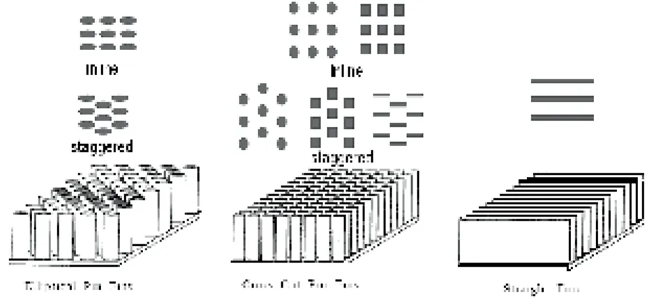
Figure 1-2: Some of the many varieties of finned tubes (Lienhard IV, et al., 2005). ... 4
Figure 1-3: Direct contribution of greenhouse gases to climate change (IEA Greenhouse Gas R&D website, 2008). ... 6
Figure 1-4: The main steps in CO2 capturing processes. ... 7
Figure 1-5: The main technologies for CO2 capturing. ... 7
Figure 1-6: Schematic diagrams of different heat sinks for tests (Christopher, et al., Feb. 2000). .... 9
Figure 1-7: Heat sink with in-line pin fins array (Moshfegh, et al., 2004). ... 10
Figure 2-1: Analysis of one-dimensional fin (Lienhard IV, et al., 2005) ... 14
Figure 2-2: Heat exchanger domain. ... 17
Figure 2-3: Studied fins: Drop-Shaped, Rectangular, and Cylindrical. ... 17
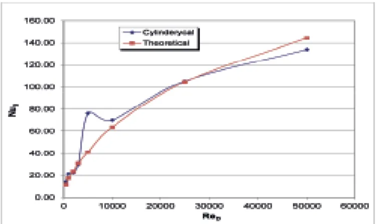
Figure 3-1: Comparison of Nusselt number in CFD modeling and theoretical model. ... 22
Figure 3-2: Film condensation on a vertical plate. ... 24
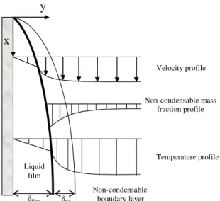
Figure 3-3: Water vapour condensation on a smooth vertical plane in presence of non-condensable gas. ... 25
Figure 4-1: Computational domain including the generic fin forms. ... 31
Figure 4-2: Nusselt number versus Reynolds number. ... 32
Figure 4-3: Friction factor. ... 33
Figure 4-4: Velocity contour (ReD = 10000, Horizontal Surface, Y=75 mm). ... 33
Figure 4-5: Temperature distribution, Horizontal surface (ReD =1000, Y= Cte) ... 35
Figure 4-6: Temperature distribution, Vertical surface (ReD =1000, X= Cte) ... 35
Figure 4-7: Temperature distribution, First pin (ReD =1000, Z = Cte). ... 35
Figure 4-8: Temperature distribution, last pin (ReD = 1000, Z = Cte). ... 35
Figure 4-9: Temperature distribution, Horizontal surface (ReD = 50000, Y = Cte). ... 36
Figure 4-10: Temperature distribution, Vertical surface (ReD = 50000, Y = Cte). ... 36
Figure 4-11: Temperature distribution, First pin (ReD = 50000, Z = Cte). ... 36
Figure 4-12: Temperature distribution, last pin (ReD = 50000, Z = Cte). ... 36
Figure 4-13: Total pressure distribution, Outlet (ReD = 50000, Z = Cte). ... 37
Figure 4-14: Simulated radiator block. ... 38
Figure 4-15: Temperature contour on the outer surface of radiator. ... 38
Figure 4-16: Temperature contour of oil (°C) in the vertical middle surface of radiators block. ... 39
Figure 4-17: Contour of velocity vector in the vertical middle surface of radiators block. ... 39
Figure 4-18: Pressure distribution in the inlet header. ... 40
Figure 4-19: Pressure distribution in the outlet header. ... 40
Figure 4-20: Radiator elements & radiator model. ... 41
Figure 4-21: Verification of model validity... 41
Figure 4-22: Oil flow rate at different inlet temperatures ... 42
Figure 4-23: Average oil velocity at different inlet temperatures ... 42
Figure 4-24: Effect of pin fin on oil mass flow rate. ... 42
Figure 4-25: Oil outlet temperature with pin fin radiator. ... 42
Figure 4-26: Comparison of heat transfer for different cases. ... 43
Figure 4-27: Schematic of oxy-fuel process (Vattenfall, 2009) and considered model for condenser.43 Figure 4-28: Comparing model results with experimental data (∆Tw-g = 18°C, P = 1 bar). ... 44
Figure 4-29: Average heat transfer coefficient versus inlet velocity and CO2 mass fraction ... 44
Figure 4-30: Condensation rate as a function of inlet velocity and inlet temperature ... 44
Figure 4-33: Effect of inlet velocity on total heat transfer coefficient. ... 46 Figure 4-34: Comparison of total heat transfer coefficient between simple case and pin-finned
List of tables
Table 1-1: CO2 emission share of large industrials activities (Metz, et al., 2006). ... 6
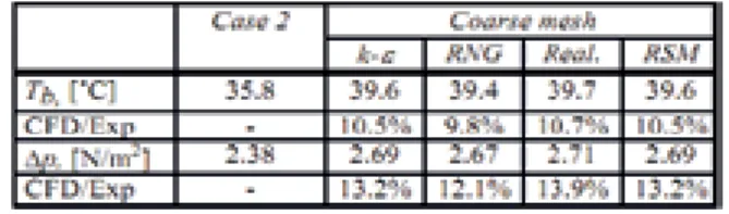
Table 3-1: Comparison of different turbulence modeling (Moshfegh, et al., 2004). ... 21
Table 3-2: Test configuration. ... 23
Contents
1. Introduction ... 3
1.1 Flow and heat transfer modeling solution for industry ... 3
1.2 Background ... 3
1.3 Motivation ... 8
1.4 Literature review ... 8
1.5 Objectives ... 12
2. Pin Fin Technology and Modeling ... 14
2.1 Basic fin theory and definitions ... 14
2.2 Pin fin study ... 17
3. Governing equations and numerical solution procedure ... 18
3.1 Introduction ... 18
3.2 Governing equations of fluid flow and heat transfer ... 18
3.3 The instantaneous equations ... 19
3.4 Simulation of pin fin model ... 21
3.4.1 Numerical mesh ... 21 3.4.2 Solution technique ... 22 3.4.3 Model validation ... 22 3.4.4 Test approach ... 23 3.4.4.1 Test matrix ... 23 3.4.4.2 Data analysis ... 23
3.5 Two-phase flow theory and modeling ... 23
3.5.1 Surface condensation theory ... 23
3.5.2 Physical model for binary system condensation ... 25
3.5.3 Mass transfer considerations ... 25
3.5.4 Influence of non-condensable gases on condensation ... 27
3.5.5 Numerical modeling of two-phase flow ... 27
3.5.5.1 Comparison of different approaches for multiphase modeling ... 27
3.5.6 Governing equations ... 28
3.5.7 Continuity equation ... 28
3.5.8 Momentum equation ... 29
3.5.9 Multiphase species transport equation ... 29
3.5.10 Energy equation ... 29
4. Results and Discussion ... 31
4.1 Introduction ... 31
4.2 Pin fin morphologies ... 31
4.2.1 Nusselt number ... 31
4.2.2 Friction factor ... 32
4.2.3 Heat transfer ... 34
4.3 Industrial application in power transformers cooling ... 37
4.3.1 Power transformer cooling system ... 37
4.3.1.2 Cooling radiators ... 40 4.3.1.2.1 Validity of models ... 40 4.3.1.2.2 Discussion on results ... 41 4.3.2 Application in CO2/H2O condenser ... 43 4.4 CFD capabilities ... 46 5. Conclusion ... 48 5.1 General discussions ... 48 5.2 Future work... 49 6. References ... 51 7. Papers Summary ... 57
1. Introduction
1.1 Flow and heat transfer modeling solution for industry
Continuous and rapid technological advances in industrial processing require that design and operation problems be resolved as quickly as possible in order to keep companies competitive, particularly in terms of energy efficiency and low costs. For many years, experiments and empirical analysis have been the preferred solution tools for industrial analysis. Despite the robust and reliable nature of exper-imental methodology, certain factors limit its applicability scope. For example, flows in process instal-lations are usually very complex; the use of experimental methodology in related analysis may demand significant simplification or a vast number of experiments to achieve an acceptable solution, indicating both cost and time constraints. Thus it has become a necessity to use advanced modeling and simula-tion tools in industry, and the number of industries benefitting from these products continues to ex-pand.
Computational fluid dynamics (CFD) is a computer simulation technique used for fluid flow and heat transfer modeling. Based on increasingly powerful computer resources, CFD can be applied to solve industrial flow and complex phenomenon problems. However, there still exists a lack of data for CFD applications in different industrial areas enabling the development of general guidelines in specific numerical heat and flow studies. This thesis attempts to provide CFD implementation methods and da-ta appropriate for those varied industrial applications.
1.2 Background
To describe the behavior of flow dynamics, governing mathematical equations are solved numerically. This is what is known as computational simulation. Results of this simulation include the approximat-ed velocity field and distribution of temperature and pressure in the entire flow domain. Relatapproximat-ed physi-cal properties (e.g., temperature profiles and density) can be extracted easily from the modeling. The intent of much current researches is to improve the heat and mass transfer models and to extend the range of chemical and physical models in CFD codes for application in industrial problems.
Fluid flows and heat transfer play critical roles in industrial processing. For example, air or water flows are regularly used for cooling purposes. Improving the cooling performance requires insight into the cooling flow profile. Typically, flow information is acquired by measuring in experimental test fa-cilities or conducting flow visualization studies. Both methods have limitations, and it is not always an easy job to get all flow parameters. Numerical methods accompanied with new modern and high speed computers have recently developed techniques to remove these limitations.
There are myriad cases in industry that can be studied and optimized using numerical simulations. Many processes contain fluid flows having multiple phases or component mixtures, all of which must be included in the simulation. For example, motion of bubbles or droplets in a fluid, mixing vessels, heat exchangers, furnaces, or HVAC equipment are typical cases that can be studied more easily by computational simulation. In turbines, fans or any other applications that contain moving parts, the numerical simulation can be implemented successfully, if correct conditions like time-variation of flow geometries are considered. In such cases, usually what is important to be calculated is transient flow field. In this thesis, numerical methods are applied in different industrial applications including: Power transformers cooling system and CO2/H2O condenser in an oxy-fuel process.
Transformers are widely used in industry, especially in power distribution networks where they are valuable assets and it is obvious that they require special attention to achieve reliable stability in power systems. Iran Transfo Corporation (ITC) is a leading Iranian manufacturer of single and three-phase oil-immersed distribution transformers that produces distribution transformer with a capacity of 12000 MVA and a power rating between 25 and 5000 kVA and a voltage ranging up to 36 kV. The energy losses in these power transformers are proportional to their loads. These losses that are typically heat losses cause temperature increment to high levels and subsequently performance of transformer de-creases. Eventually its operational load capacity and its useful life are reduced. In small transformers heat removal through the unit’s own surface by natural convection is typically enough. However, this kind of heat removal is not enough for transformers of average and high power, which require more elaborate methods of cooling and generated heat removal (Carrothers, et al., 1961). In the ITC trans-formers, cooling is provided by the circulation of oil between ducts in the active parts and heat ex-changers outside the transformer tank; this oil circulation results from free convection, or combined free and forced convection. Based on transformer design, it is in the interest of ITC to minimize the size of heat exchangers and internal cooling ducts.
In the literature, few studies exist on heat transfer and fluid flow outside the transformer; most have focused on processes inside the transformer. For example, Mufuta and Van Den Bulck (Mufuta, et al., 2000) studied a winding disc-type transformer. Results showed that there is a strong relation between Re.Gr−1/2
parameter and flow behavior. They presented some correlations for the heat transfer calcula-tion inside the transformer. Heat transfer inside channels and the thermal behavior of flow in a pipe with different boundary conditions have been investigated widely in heat transfer texts, but no research with focus on the radiator has been found in the literature.
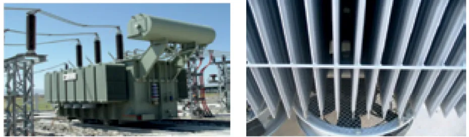
A typical transformer is shown in Figure 1-1. To achieve better performance, conventionally fins are added to plain tubes resulting in a larger external surface area, a higher heat transfer performance, and smaller dimensions. Figure 1-2 shows some various fins commonly used in heat exchangers.
Figure
Figure Figure
Figure 1111----1111:::: TTTTypical power transformer equipped with auxiliary fans ypical power transformer equipped with auxiliary fans ypical power transformer equipped with auxiliary fans ypical power transformer equipped with auxiliary fans (Iran Transfo Corpora-tion Documents, 2005).
One of the most interesting developments in enhanced heat exchanger design is in pin fin technology. Pin fins are proper solution in heat transfer enhancement in various applications including gases or liquids. They are manufactured from various materials including brass, copper, carbon steel, alumi-num/brass, and other metal alloy. In recent years, this technology has become a major design compo-nent for electronics cooling. Its excellent capacity for heat transfer logically extends its use from elec-tronics to industrial heat exchangers. This technology could remove or at least decrease most of the problems incorporated with heat exchangers operation: large pressure loss and low total heat transfer efficiency. Pin fin structure significantly increases the heat transfer surface area at both side of tube, with a reduced thickness of the boundary layers. Some of its features are presented below (Gree Thermo-Tech Co., Ltd. of Zhuhai, 2005):
“- Convection heat exchanging coefficient for single-phase fluid is 2.5 to 6 times higher than that of
the plane tube.
- Boiling heat transfer coefficient is 2 to 5 times higher than that of the plane tube. - Condensing heat transfer coefficient is 3 to 6 times higher than that of the plane tube. - Unique self-cleaning feature greatly reduces maintenance cost of heat exchangers.”
Few companies produce pin fin tubes for use in heat exchangers' applications. Gree Thermo-Tech Co, Ltd. in China is a major producer and recommends them for use in different types of heat exchangers. However, no technical data are currently available on that company's web page (perhaps because the technology is still cutting edge and, therefore, highly guarded). Another company which uses this technology in its products is Raypak Company in the USA. The pin fin tubes are widely used in the company's heating products. It seems possible that the study of pin fin's applicability in heat exchang-ers could generate attractive solutions to challenges in heat exchangexchang-ers' field and produce more effi-cient and compact heat exchangers.
The pulp and paper industry may present a strong potential for using this technology. The industry consumes a sizeable portion of primary energy consumed in the industrialized countries’ manufactur-ing. The heart of the pulp and paper mill is its recovery boiler, which consists of several heat transfer components including a super heater, a reheater, an economizer, an evaporator and air heaters. Super heaters (especially the radiant types) are made from smooth tubes, which are less expensive and sim-pler to manufacture than finned ones; they are also less prone to fouling and can be cleaned easily. The drawback to their use is that in a moderate gas flow velocity, the heat absorption is limited. Important-ly, heat transfer through tubular surfaces is restricted by the heat passing through the tube’s external surface and therefore can be increased by extending (expanding) that surface. In light of the new e-cooling technologies used to improve energy efficiency, surface enhancement using pin fins could be a promising method to surmount the described problem as well as improve efficiency and reduce maintenance. Moreover, there are other heat exchangers used in the pulp and paper mills (for example in the drying section) which can operate with higher efficiency using enhanced heat transfer surfaces. Another emerging issue that may be resolved through technological advances concerns greenhouse gases effect and global warming. When sunlight passes through the atmosphere and reaches to the earth’s surface, it is converted to heat. Some of this heat reflects directly to space in the form of infra-red radiation and some is absorbed by greenhouse gases. This absorption is a natural phenomenon which helps keep the temperature of the earth at a level that makes it possible for life to exist. It ap-pears that human activities have caused an increase in the level of greenhouse gases and, consequently, the global temperature has risen. It is so important to limit this change, so natural and human systems can adapt themselves to this change. One of the most important ways to control the rate of global tem-perature change is to reduce greenhouse gases in the atmosphere and thereby decrease their heat ab-sorption.
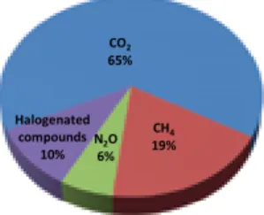
The main greenhouse gases that contribute to global temperature rising are: carbon dioxide (CO2),
me-thane (CH4), nitrous oxide (N2O), perfluorocarbons (PFC’s), halo carbons (HFC’s), and sulphur
hex-afluoride (SF6). Figure 1-3 shows the direct contribution each. Among these, the main anthropogenic gas is CO2. Approximately one-third of all CO2 emissions come directly from electricity production
sections that use fossil fuel combustion to generate electricity. Other industrial processes (including oil refineries, cement factories and steel producers) generate 40% of these emissions and the reminder comes from mobility and other sources. The CO2 emissions from electricity production and other
in-dustrial processes could be substantially reduced by capturing and storing the CO2, without major
changes to main process. Table 1-1 shows CO2 emissions from different major industrial resources.
From this data, it is fairly obvious that carbon capturing and sequestration in stationary sources such as fossil fuel power plants is one of the important solution in reducing the CO2 presence in the
atmos-phere.
Figure 1-3: Direct contribution of greenhouse gases to climate change (IEA Greenhouse Gas R&D website, 2008).
Various methods exist for reducing greenhouse gas emission such as reducing energy demand, im-proving energy efficiency, and switching to fuels with low or no carbon contents. These methods are good but insufficient. Since the world is at present heavily dependent on the exploitation and use of fossil fuels, it is important to focus on technologies for the capture and storage of CO2 produced by the
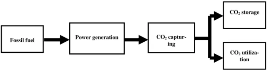
combustion of fossil fuels. Figure 1-4 shows the main steps in the CO2 capturing process in a
fossil-fuel power plant. First the fossil fossil-fuel is combusted to produce power; and then CO2 is separated from
combustion products. Finally depending on available facilities, the CO2 is either used or stored.
Available technologies in CO2-capturing are categorized into three main groups (Davison, et al.,
2001):
• Post-combustion: CO2 is captured from combustion products
• Pre-combustion: CO2 is removed from the fossil fuel before combustion process
• Oxy-fuel: pure oxygen is used for fossil fuel combustion
Table 1-1: CO2 emission share of large industrials activities (Metz, et al., 2006).
Process Emissions (MtCO2 per year)
Fossil fuels
Power 10.539
Cement production 932
Refineries 798
Iron and steel industry 646
Petrochemical industry 379
Oil and gas processing 50
Other sources 33
Biomass
Bioethanol and bioenergy 91
CO2 65% CH4 19% N2O 6% Halogenated compounds 10%
Figure 1-4: The main steps in CO2 capturing processes.
Figure 1-5 shows the main technologies which are used for CO2 capturing in power plants. The
tech-nical and economic comparison of the three technologies for large-scale industrial applications (like power plants) is still under study and a preferable technology may highly depend on further develop-ment and commercialization of the technologies.
This work considers the third technique, involving oxy-fuel combustion. Oxy-fuel systems use pure oxygen for fuel combustion, and the resulting flue gas contains mainly water vapour and CO2. The
CO2 concentration of flue gas is high (greater than 80% by volume) and the water vapour content must
be removed by condensation process in a CO2/H2O condenser. This technology is not fully mature.
The operation and management as well as capital costs would be comparable to post-combustion cap-ture; in specific, the oxygen separation unit consumes about 23%–37% of the total plant output and costs about the same as the absorber. To gain the high efficiency in H2O removal from flue gas and to
prepare a pure CO2 stream, a precise condenser design is required. Despite wide usage of condensers
in different industries, complete design data and codes are not yet available, especially for condensers that involve multi-component mediums. Thus new experimental and numerical studies are necessary to achieve the desired efficiency in CO2 capturing and steam separation. Significant technical
chal-lenges regarding the condenser design must first be addressed before this method can be implemented. This option is most appropriate for new plant projects rather than for retrofitting existing plants. The main effort in the current project deals with the technical challenges of condenser design for CO2
cap-turing using the oxy-fuel method.
Figure 1-5: The main technologies for CO2 capturing.
Fossil fuel Power generation CO2
captur-ing
CO2 storage
CO2
1.3 Motivation
Compact heat exchangers (CHE) have recently become subject to extensive research because of their importance to a wide variety of engineering applications. Fins play a vital role in enhancing their per-formance.
Radiators used in power transformers are typical heat exchangers. However, their performance is not sufficient to resolve the overload conditions that take place during the hot seasons; therefore, it may be advantageous to use pin fin technology either inside or outside these exchangers to enhance their effi-ciency. Studies seeking to improve the heat transfer characteristics of radiators could involve changing the oil flowing passage profile, changing the radiator dimensions, or using width-wise pin fins between radiators, all of which require a solid understanding of pin fins behaviour and their heat transfer char-acteristics.
Large numbers of different heat exchangers are used in vital industries like power plants, power trans-formers, and pulp and paper mills, especially in their steam boilers—the heart of the industrial plant. The efficiency of the gas-side heat transfer is a primary consideration when determining the best heat exchanger for a particular application. Surface enhancement using pin fins could be a promising meth-od to overcome the described problem as well as to improve maintenance requirements. As yet, no de-tailed study on the performance of such finned tubes has been carried out; the present research investi-gates the heat transfer characteristics of different shaped pin fins from numerical point of view. The increase in greenhouse gases has caused the global temperature to rise and will eventually cause the global climate to change. CO2 is the main anthropogenic gas, derived from fossil fuels for use in
industry, and carbon capture and sequestration to reduce its release into the atmosphere is of critical importance. The power plant’s flue gas contains high CO2 concentrations (greater than 80% by
vol-ume). Therefore, there is a significant need for an efficiently designed CO2/H2O condenser to capture
this amount of CO2. Despite of wide referring to this kind of condenser in different proposed Oxy fuel
cycles; the appropriate design data are not yet available. New experimental and numerical studies are necessary to achieve the desired efficiency for CO2 capturing and steam separation. Basic studies on
water vapour condensation in presence of CO2 as non-condensable gas can provide useful technical
data for designers.
There are still many emerging concepts such as CO2 capturing technologies that are being developed
and assessed throughout the world and they need efficient tools to be evaluated carefully. CFD can be used as a robust tool for simulating the conceptual design in such projects before manufacturing and operating experiments, reducing the total effort required in experimental design and data acquisition. This means that the experiments can be performed once the design is more mature, resulting in the saving of both time and money. Technical efforts and practical bottlenecks in mathematical modelling may remain challenges; this thesis will focus on reducing some of them.
1.4 Literature review
This section presents a brief look at the existing research. It also includes a discussion of current state-of-the-art issues and optimization techniques involved with thermal management in heat exchangers and e-cooling. In addition, a comprehensive literature survey was conducted to identify previous re-search on two-phase flow modeling; this is applicable to the thesis section related to CO2 capturing
and condensation.
One of the most referenced relevant works is that of Christopher L. Chapman and Seri Lee (Christo-pher, et al., Feb. 2000). They carried out comparative thermal tests on aluminum heat sinks with both rectangular and elliptical-shaped pin fins for low ranges of air flows. In their design, the heat transfer surfaces were kept as large as possible and vortex flows were minimized by implemented airfoils.
The basic assumption in their research was that both heat sink (with elliptical fins and conventional fins) have same volume. They used thermal resistance and flow bypass quantities to measure the ef-fects of different parameters like pressure drop, flow characteristics, and thermal conductivity on cool-ing performance of heat sink. Different heat sinks that used in their experimental test set-up are sche-matically shown in figure 1-6.
Chapman and Lee found that with same thermal resistance, heat sink with rectangular fin has about 40% more air flow, while the elliptical fin design shows better heat transfer characteristics. They found that for a wide range of air flow, the extruded straight design has meaningfully better perfor-mance compare to the other designs.
Figure 1-6: Schematic diagrams of different heat sinks for tests (Christopher, et al., Feb. 2000).
Boulares (Jihed Boulares, 2003) studied the pressure drop and heat transfer characteristic of a com-pact heat exchanger which equipped with pin fins. He used ANSYS to conduct numerical modeling to achieve optimum pin fin form and heat exchanger configuration. Then based on numerical results, he performed an experimental study that validated the numerical model.
More recently, Moshfegh and Nyierdy (Moshfegh, et al., 2004) discussed different approaches for numerical modeling of turbulent flow with application in electronic cooling. Their guidelines are very useful for similar works. They simulated a circular pin fin heat sink with a 3-D model. (Figure 1-7). Channel Reynolds numbers were adjusted to a range between 5000 to 14500 by applying proper inlet velocity. A wide range of results were investigated including pressure drop, temperature distribution, and flow bypass effects. The Gambit grid generation package was used to generate an unstructured 3D grid. Considering the symmetric shape of channel, only half of it was modeled. For better computa-tional results, two grids with different mesh density were used and in the areas close to the pins the finer mesh were implemented. Their results showed that both the pressure drop and the heat transfer coefficient are dominated by proper turbulence model and correct near near-wall treatments.
Because of the various industry applications for finned tubes, there are many different fields of re-search. Research papers referred to frequently in the literature concern correlations (Kröger, 1986), convection (Hahne, et al., 1994)and conduction (Ranganayakulu et al., 1999).
Figure 1-7: Heat sink with in-line pin fins array (Moshfegh, et al., 2004).
Performance of different types of finned-tubes has been assessed by Kroger (Kröger, 1986). He de-rived a method to evaluate the pressure drop and heat transfer characteristics of such a finned tubes. Another correlation for finned-tubes was empirically derived by Idem et al. (Idem, et al., 1987). This correlation is useful in prediction of hydrothermal performance of other heat exchangers with similar configuration.
The purpose of an extended surface heat exchanger is to increase heat transfer. In this section a couple of heat exchangers have been review from this point of view. The literature study was limited to roughened surfaces, finned tubes, offset strip fins, pin fins, and micro fins as follows:
• Roughened Surfaces
Heat transfer enhancement takes place through roughened surfaces by promoting turbulence (Bergles, 1988). In an article by Firth and Meyer (Firth, et al., 1983)the ribs of four different surfaces were even-ly spaced and the heat transfer coefficients and friction factors were compared. Zhang et al. (Zhang, et al., 1994) used a parallel plate channel with staggered ribs to study the effects of compound turbulators on both heat transfer coefficient and pressure drop. The results of these articles showed that any ad-vancement in heat transfer was counter-balanced by the pressure drop. Several different configurations were studied to find the design with the least pressure drop. Finding the best rib angle was the objec-tive of a paper by Han et al. (Han, et al., 1978). It was found that ribs at a 45° angle of attack had bet-ter heat transfer characbet-teristics than those with a 90° angle of attack for a given pressure drop. The ef-fects of conduction were included in a study by Webb and Ramadhyani (Webb, et al., 1985). While investigating the heat transfer and friction properties for a parallel plate channel with staggered ribs, they found that conduction in the channel walls contributed to an enhanced heat transfer.
• Internally Finned Tubes
An internal finned tube is round or rectangular with continuous fins inside it which enhance heat trans-fer. An advantage of these tubes is that they provide an easy and efficient way to enhance internal convection (Zhang et al., 1996). In Soliman et al.’s paper (Soliman, et al., 1980), the distribution of fluid temperature, fin temperature, and local heat flux with a uniform outside wall temperature was numerically derived for both finned and unfinned configurations. The results showed that the distribu-tion of heat flux was dependent on the quantity of fins and the fin height, and that a finned tube had better heat transfer characteristics surface than a smooth tube. Renzoni and Prakash (Renzoni et al., 1987) derived heat transfer flow characteristics for developing flow in the entrance region of an inter-nally finned heat exchanger. Their theoretical results showed the relation between Nusselt number and pressure drop for the entrance regions as well as estimates for the hydrodynamic and thermal entrance lengths. Two studies of laminar flow in internally finned tubes were completed by Rustum and Soli-man (Rustum, et al., 1988) (Rustum, et al., 1990) and both focused on mixed convection. Experimental results for the pressure drop and heat transfer characteristics for laminar flow were given in their first paper (1988); these showed that the free convection had a great effect on heat transfer and approached the forced-convection predictions as the Rayleigh number decreased. Their numerical analysis was based on the geometrical parameters like fin height and number of fins, and also Prandtl number and
modified Grashof number. From the analysis, the temperature distribution, secondary flow, wall heat flux, axial velocity, friction factor and average Nusselt number were derived. Available experimental results were compared with analysis result, and a good correlation was found. Other conclusions were that influence of free convective was delayed, and that the enhancement of the friction factor and Nusselt number was suppressed.
In internally finned tubes, the flow can also be turbulent. This condition was analysed by Patankar (Patankar et al., 1979), Webb and Scott (Webb, et al., 1980), and Kim and Webb (Kim, et al., 1993). a mixing length model was used by Patankar (Patankar, et al., 1979)for analysing an internally finned tube. For their analysis, the friction factor and the Nusselt number were derived. The results also showed that the fins were a better transfer surface than the tube wall. Webb and Scott analysed an in-ternally finned tube for three design cases by (Webb, et al., 1980):
• reduced tube material volume for equal pressure drop and heat transfer;
• increased heat transfer for equal pressure drop and heat transfer surface area of heat exchanger; and
• reduced pressure drop for equal heat transfer and heat transfer surface area of heat exchanger. Their results showed that although material savings were found using axial internal fins, much better savings were obtained when the fins had a helix (twisted) angle. A comparison with the empirical Car-navos correlations was made in the analytical model used by Kim and Webb (Kim, et al., 1993) in their article about axial internal fin tubes. The friction factor and heat transfer equations were derived and predicted the Carnavos friction data within 10% accuracy and the Carnavos heat transfer data within 15% accuracy.
• Finned Tubes
A finned tube heat exchanger consists of a tube with fins on the exterior wall. These are used in appli-cations such as water heaters and boilers (Idem et al., 1987). Because of the varied industrial applica-tions for finned tubes, there are many different fields of research related to them.
• Offset Strip Fins
Offset strip fins heat exchangers are mostly used in cooling systems such as air conditioning equip-ment (Carey, 1985). Basically, a recirculating flow forms between two succeeding fins and conse-quently fully developed flow condition will never establish. This means a continues boundary layer formation which enhances the heat transfer considerably. (Kelkar et al., 1990).
• Pin Fins
This type of fin was introduced earlier in this chapter. • Other enhancements
The above selections represent only a portion of the range of enhanced heat exchanger configurations. For example, twisted tape inserts can be placed inside tubes (Royal, et al., 1978) to increase the heat transfer. Other enhanced heat exchangers include the plate-fin arrangement and the louvered fin com-pact heat exchanger (Xiao, et al., 1992) (Krishnaprakas, 1996) (Tagliafico, et al., 1996) (Atkinson, et al., 1998). Another popular fin pattern for heat transfer enhancement is the wavy fin configuration (Wang, et al., 1999). In this paper, correlations for the airside performance of a wavy fin heat ex-changer were derived using samples. A generalized heat transfer coefficient and friction factor was proposed that were within 15% of the sample data.
As part of this thesis focuses on heat and mass transfer in CO2/H2O condensers, a brief of literature
re-views of that topic is presented here. Recently, researchers have been working on steam condensation and condensation from non-condensable mixtures. Direct contact condensation inside a rectangular channel is investigated experimentally by (Ruile, 1995). In Dehbi work (Dehbi, et al., 1997) theoreti-cal prediction of heat and mass transfer from steam and noncondensable gas mixtures within a vertitheoreti-cal tube was calculated by deriving an algebraic equation for the film thickness from momentum balance, considering the interfacial shear stress influences. Then calculate the condensation rate, mass and heat transfer analogy approach were implemented. In 1998, Herranz studied the steam condensation and
diffusion layer model for a Westinghouse containment. They applied a mass and heat transfer analogy to model the thermal resistance and wavy structure of the condensing film. Shortly thereafter, Liu ex-amined the condensation heat transfer coefficient in vertical smooth tubes with different fractions of non-condensable gas (Liu, et al., 2000). They showed that condensation heat transfer is lower when helium exists in the system compared to one with air in it. In 2002, Choi performed experiments on di-rect contact condensation when stream contains non-condensable gases (Choi, et al., 2002). They in-vestigated water vapour condensation of steam and steam–air mixtures on the subcooled water film flows. The local empirical values for heat transfer coefficients were obtained for different mass frac-tions of non-condensable gas at the inlet.
Based on the literature survey, it appears that only a very few attempts have been performed on a CFD application in study of condensing flow. Yadigaroglu (Yadigaroglu, 2003) noted that computational dynamics for multi fluids mixtures is still under development and requires additional research. One of the most recent works is by Wilhelmsson (Wihelmsson, et al., 2007). They employed a CFD approach to model water vapour condensation in a channel inside a plate heat exchanger and developed their model based on the governing equations and solved them for the entire single and two-phased fields. Another recent work is by Kljenak (Kljenak, et al., 2006), in which CFX4.4 was employed as the computational fluid dynamics tools. Studied model consists of a big cylindrical vessel in which steam, air and helium gases are injected and conditions on vessel walls causes steam to be condensed on them. The goal was to simulate condensation in a non-homogeneous mixture and get the right conden-sation rate. A 2-D axisymmetric vessel model was created using CFX4.4 code. The approach modeled the flow in the domain simulation as single-phase while it considered the steam condensation as a sink of energy and mass. It was noted in Klejnak’s work that the modeling of steam condensation is not available in CFD codes and must be applied correctly by users. The condensation model was fed to CFX by used defined function and applying the theoretical correlations, and different theoretical con-densation models were identified.
Another recent work involves the mechanistic modeling of water vapour condensation in a mixture of steam and non-condensable gases (Karkoszka, 2007). This thesis presents the analytical and numeri-cal analysis of the water vapour condensation from the multi-component mixture of condensable and non-condensable gases in the area of the nuclear reactor thermal-hydraulic safety. Surface condensa-tion, liquid condensate interaction with gaseous mixtures and spontaneous condensation in supersatu-rated mixtures have been taken into consideration throughout the thesis. It was found that in all cases that condensation heat and mass transfer rates are significantly dependent on local mixture intensive parameters (such as the non-condensable species concentration). Both analytical and numerical meth-ods were used to find the influence of the light gas and induced buoyancy forces on the condensation heat and mass transfer processes.
Analysis was performed applying the boundary layer approximation and the similarity method to the system of film and mixture conservation equations. Numerical analysis was performed with the in-house-developed code and commercial CFD software.
The survey suggested that the greatest efforts have focused on developing the mathematical modeling for multi-phase flow and that no actual CFD modeling has been done for a condenser itself. The win-dow is open, therefore, for evaluating the derived models and applying them to commercial CFD soft-ware (e.g., Fluent) to obtain realistic results as guidance for the improved design of multiphase con-densers.
1.5 Objectives
The final goals of this thesis are to evaluate and implement CFD-based methods for realistically pre-dicting heat transfer and fluid flow in some industrial applications related to power generation with the intention of heat transfer efficiency improvement and to provide useful information for designers in
fore, different fin geometries featuring typical flow-heat transfer characteristics are investigated and evaluated. Then different numerical methods are evaluated for different applications, and the ad-vantage and disadad-vantages of each are investigated.
The main focus is on the investigation on flow and heat transfer prediction and improvement in indus-trial heat exchangers by CFD methods. However a brief study of the principal physical models of all cases is included.
2. Pin Fin Technology and Modeling
2.1 Basic fin theory and definitions
Generally, when the convective heat transfer coefficient is small (a condition commonly encountered when the surrounding fluid is a gas), the rate of heat transfer can be increased considerably by in-stalling an extended surface or a fin on the surface. This part is taken mainly from Lic thesis to keep the consistency of research in the Phd Thesis and give an overall view of pin fins theory.
Here the focus is on the pin fins which provide heat transfer augmentation via the disturbing in laminar boundary layers growth. To show the essential features of fin behavior and introduce the basic defini-tions, we start with the analysis of a straight fin protruding from a wall. Figure 2-1 shows such a fin with a one-dimensional characteristic.
Figure 2-1: Analysis of one-dimensional fin (Lienhard IV, et al., 2005)
The temperature of the fin’s root is kept constant at T0. The fin body is cooled (or heated) by ambient
air, and its temperature is assumed to be T∞. The convective heat transfer coefficient,h , is supposed to be uniform along the whole length of the fin. Though this assumption is not very accurate, we use it to formulate the fin behavior. The temperature distribution along the fin is necessary to obtain its asso-ciated heat transfer. Considering the negligible radiation heat transfer from the fin surface and the one-dimensional conduction through the fin, the energy balance on a thin differential element is shown in the following equation
−.
+ .
+ ℎ. . ). − )= 0 2-1)
Rearranging equation 2-1 yields the equation 2-2 such that
)
=. − ) 2-2)
Boundary conditions for this equation are shown in the equations 2-3(a) and 2-3(b).
− )= − 2-3a))
−)
= ℎ. . − ) 2-3b))
For the case of negligible heat transfer at the fin tip (like an insulated tip), the boundary conditions can be considered as equations 2-4(a) and 2-4(b).
− )= − 2-4a))
−)
= 0 2-4b))
To work with dimensionless parameters, we use the following substitutions. =
2-5a))
= 2-5b))
= 2-5c))
These equations can be rearranged to give a more general form.
= ). 2-6)
This equation is satisfied by
θ
=C.e±(mL)ξwhich can be written in the following form to yield the gen-eral solution of equation.
= . + . 2-7)
C1 and C2 will be calculated according to boundary conditions, and they are different in different
cas-es. It is obvious that the mL is a useful parameter in the analysis and design of fins. It can be rear-ranged as equation 2-8. )= . 1 ℎ. . ) = 2-8) When 2 )
(mL is big, θξ=1→0and tip convection can be neglected. When it is small, the temperature
One of the most important design variables for a fin is the rate at which it removes (or delivers) heat from/to the wall. To calculate this, the Fourier’s law for the heat flow into the base of the fin is written. = −)
2-8)
Two other basic measures of fin performance which are particularly useful in a fin design are fin effi-ciency, ηf and fin effectiveness, εf (Hewitt, 1990):
= 2-9)
= 2-10)
Though ηf provides some useful information about fin design, there is not a particular ηf which
repre-sents the best design. On the other hand, it seems that the effectiveness should be as high as possible which is always achievable by extending the length of the fin. However, this solution is a losing prop-osition. For a reasonable design, εf should be as large as possible and generally, when εf ≤ 2, there is
no use for fins.
The fin effectiveness can be increased by the following considerations:
• Selection of high conductive materials (such as copper and aluminum, however, aluminum is more usual, because of its lower price and weight).
• Increase in the circumference to section area ratio. This is the reason for using thin fins in engi-neering applications.
• Using fins in cases that the convection heat transfer coefficient (h) is low.
Thus fin design is still an open-ended subject of optimizing, subjected to many factors. Lienhard has summarized some of them (Lienhard IV, et al., 2005):
“1- The weight of material added by the fin.
2- The possible dependence of h on (T - T∞), flow velocity past the fin, or other influences. 3- The influence of the fin (or fins) on the heat transfer coefficient, h.
4- The geometric configuration of the channel that the fin lies in. the cost and complexity of manufac-turing fins.
5- The pressure drop introduced by the fins”.
The last parameter that we are dealing with in this section is fin thermal resistance which is defined as the ratio of a temperature difference to the resultant heat transfer rate. This means that the fin acts as a thermal resistance between the root and the surrounding ambient. For a straight fin with negligible heat transfer at its tip, we have:
= ) . ))= ) , 2-11) where: ,=. ) ℎ 2-12)
Equation (2-12) implies rate of the heat which the fin can remove from the wall. The relation between the fin thermal resistance and other fins parameter can be derived from foregoing equations and writ-ten as equation 2-14.
,=. . =. . 2-13)
2.2 Pin fin study
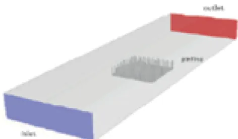
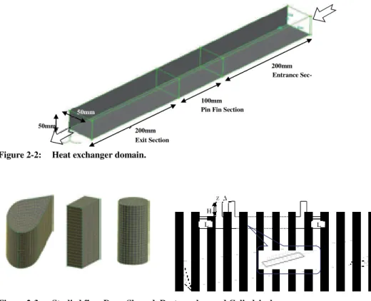
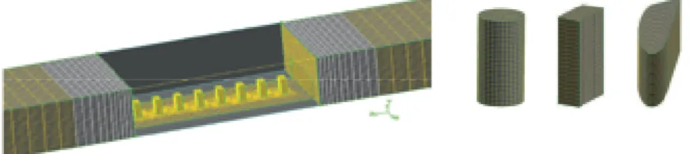
In this study, three different cases are considered. The heat exchanger domain consists of three con-nected channels: an entrance section, a pin fin section and an exit section. The pin fin section consists eight rows of in-line pin fins with axes perpendicular to the flow, as shown in figure 2-3. Three differ-ent pin shapes are considered: cylindrical, rectangular, and drop-shaped. The main geometrical dimen-sions that characterize the heat exchanger are the pin height (H), the diameter of the cylindrical portion of the pin (D [note that for rectangular pin fin this parameter is considered as fin width]), the stream-wise pin spacing (∆) and the pin-tail length (Z). Figure 2-3 depicts more details on these parameters. The pin width (D) was kept constant at a value equal to 5 mm and was considered as a reference length scale. The total pin fin area is equal for all pin fins. The entrance duct was constructed in front of the heat exchanger pin fin section to ensure a fully developed laminar flow condition at the entrance to this section. An exit duct was also used to ensure well-mixed conditions at the exit plane. Both the en-trance and exit duct are assumed to be adiabatic.
Figure 2-2: Heat exchanger domain.
Figure 2-3: Studied fins: Drop-Shaped, Rectangular, and Cylindrical.
H ∆ L L Z Entrance Sec-tion Exit Section
Pin Fin Section 200mm
100mm
200mm
50mm
3. Governing equations and numerical solution procedure
3.1 Introduction
The finite volume method (FVM) is based on decomposition of the physical domain into small cells which are called control volumes. The equations governing fluid flow are integrated formally over all the (finite) control volumes of the solution domain. Resulted integral equations are discretized into a system of algebraic equations by substituting finite difference approximations in them in order to rep-resent different term such as diffusion , convection, and sources. Finally these algebraic equations are solved iteratively. More complete details can be found in various CFD text books (e.g. (Versteeg et al., 2007) (Anderson, 1995)). Discretisation schemes exhibit different properties; among these, the First and Second Order Upwind, QUICK (third order), Power Law and Third-Order MUSCL are most fre-quently used in CFD codes.
Algorithms for pressure-velocity coupling in steady flows include SIMPLE, SIMPLEC and PISO (Versteeg et al., 2007). In most instances, this thesis applied the SIMPLE algorithm unless a conver-gence problem occurred. In such cases, SIMPLEC or PISO algorithms were used to determine a con-verged solution. In all cases, the physical properties of fluids were assumed to be dependent on tem-perature. This assumption aligns the results more closely with reality, especially in cases with large temperature variations.
In two-phase flow regimes, there are more complexities involved and special considerations should be taken into account. These issues are discussed in a later section of this chapter.
3.2 Governing equations of fluid flow and heat transfer
Considering the following conservation laws, which are proved that govern the fluids dynamic behav-ior, the mathematical governing equation can be derived:
1. mass conservation; 2. momentum conservation; 3. energy conservation.
The law of mass conservation states that mass cannot be created in a fluid system, nor can it disappear from one. Any variation of mass would imply a displacement of fluid particles. This fact is represented mathematically by the following continuity equation.
+ ) = 0 3-1)
Navier–Stokes equations govern the motion of viscous fluids. They are obtained by applying the New-ton's second law of motion to fluid flow with some extra relevant assumptions for stress terms and considering pressure gradient. The Navier–Stokes equations are differential equations that represent the correlation between rates of change of different flow variable (e.g. velocity and pressure). A solu-tion for these equasolu-tions is called the flow field or velocity field, which describes the velocity of a fluid at a given point in space and time. Other fluid flow properties such as flow rate can be determined