EVALUATION OF SOURCE ROUTING FOR
MESH TOPOLOGY NETWORK ON CHIP
PLATFORMS
Saad Mubeen
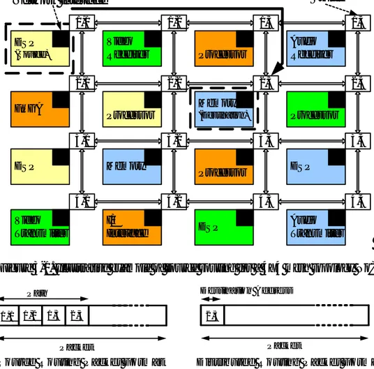
DSP (Source) 1,1 Video Receiver 1,2 Processor 1,3 Audio Receiver 1,4 FPGA 2,1 Processor 2,2 Nios-II 2,3 Processor 2,4 DSP 3,1 Memory 3,2 Processor 3,3 DSP 3,4 Video Transmitter 4,1 I/O Interface 4,2 Memory (Destination) 4,3 Audio Transm itter 4,4 Encoded Path 11 00 10 00 Path 1,1 2,1 2,2 3,2 3,3 4,3 10 10 Packet Header Packet HeaderEVALUATION OF SOURCE ROUTING FOR
MESH TOPOLOGY NETWORK ON CHIP
PLATFORMS
Saad Mubeen
This thesis work is performed at Jönköping Institute of Technology within the subject area Electronics. The work is part of the university’s two-year master’s engineering degree.
The authors are responsible for the given opinions, conclusions and results.
Supervisor and Examiner: Shashi Kumar Credit points: 30 points (D-level)
Abstract
Abstract
Network on Chip is a scalable and flexible communication infrastructure for the design of core based System on Chip. Communication performance of a NoC depends heavily on the routing algorithm. Deterministic and adaptive distributed routing algorithms have been advocated in all the current NoC architectural proposals. In this thesis we make a case for the use of source routing for NoCs, especially for regular topologies like mesh. The advantages of source routing include in-order packet delivery; faster and simpler router design; and possibility of mixing non-minimal paths in a mainly minimal routing. We propose a method to compute paths for various communications in such a way that traffic congestion is avoided while ensuring deadlock free routing. We also propose an efficient scheme to encode the paths.
We developed a tool in Matlab that computes paths for source routing for both general and application specific communications. Depending upon the type of traffic, this tool computes paths for source routing by selecting best routing algorithm out of many routing algorithms. The tool uses a constructive path improvement algorithm to compute paths that give more uniform link load distribution. It also generates different types of traffics. We also developed a simulator capable of simulating source routing for mesh topology NoC. The experiments and simulations which we performed were successful and the results show that the advantages of source routing especially lower packet latency more than compensate its disadvantages. The results also demonstrate that source routing can be a good routing candidate for practical core based SoCs design using network on chip communication infrastructure.
Sammanfattning
Sammanfattning
Network on Chip (NoC, sv. Nätverk på Chip) är en flexibel kommunikations-struktur för avancerade System on Chip (SoC, sv. elektroniksystem på chip). Prestanda i dessa nätverk är till stor del beroende av vilken routing-algoritm som används. Både statiska och dynamiska routing-algoritmer har föreslagits som lämpliga för NoC. I detta dokument visas att source routing (sv. Sändar-kontrollerad routing) passar väl för NoC-system. Flera egenskaper är till dess fördel, inte minst möjligheten till snabba, enkla routrar och enkel styrning av nätverkstrafik.
Vi presenterar en metod som beräknar effektiva paketrutter för flera typer av trafik och samtidigt garanterar frihet från dödlig låsning. Till detta föreslås även ett effektivt kodningsschema. Matlab har använts för implementering av ett program, baserat på de föreslagna teknikerna. Programmet kan, till exempel, hitta den routing-algoritm som fördelar nätverkskommunikationen mest jämnt för en viss trafiktyp. Om så önskas kan även särskilda typer av trafik genereras. En nätverkssimulator för source routing har även utvecklats. Genoförda simuleringar visar att source routing ger bra prestanda, särskilt med avseende på transmissionstid för paket. Resultaten leder oss till slutsatsen att source routing är en bra och praktisk kommunikaitonsstrategi för NoC.
Key Words
Network on Chip (NoC) System on Chip (SoC) Core Based Design On Chip Communication Distributed Routing Source Routing Routing Algorithms Performance Analysis Packet Switched Network
Acknowledgements
Acknowledgements
First of all, I would like to thank my supervisor Professor Shashi Kumar for the encouragement and guidance which he provided me throughout this thesis. I had a great opportunity of learning so many things from him in the meetings and brainstorming sessions. It is worthy to mention that it is an honor for me to accomplish master thesis in the area of Network on Chip under the supervision of one of the founders of Network on Chip paradigm.
I would like to thank Rickard Holsmark for providing a SystemNoC simulator that was used to build a simulator for source routing. I thank him for his time and effort which he spent in debugging the simulator for hours. Without his help, the simulation results were not possible in such a small span of time. I would like to thank master program coordinator Alf Johansson for being always helpful and caring.
I would like to thank all my teachers for delivering great and invaluable knowledge. They are true educators and possess great knowledge.
Table of Contents
Table of Contents
1 Introduction ... 1
1.1 SYSTEM ON CHIP...1
1.1.1 Chip Capacity ...1
1.1.2 Core Based Design ...1
1.1.3 Limitation of Buses and Interconnections...1
1.2 NETWORK ON CHIP...2
1.3 NOCDESIGN ISSUES...2
1.3.1 Topology ...2
1.3.2 Core Selection...3
1.3.3 Routing Algorithms and Router Design ...3
1.4 THESIS OBJECTIVES AND TASKS...4
1.5 THESIS LAYOUT...4
2 Network on Chip ... 6
2.1 EVOLUTION OF ON-CHIP PACKET SWITCHED NETWORKS...6
2.1.1 Point to Point Connections ...6
2.1.2 Bus Based Integration ...7
2.1.3 Packet Switched Network Based Integration...7
2.2 EXISTING NOCARCHITECTURE PROPOSALS...8
2.3 NOC:PROTOCOLS AND CONCEPTS...9
2.3.1 Layered Communication ...9
2.3.2 Network Communication Definitions...9
2.3.3 Switching Techniques ...10
2.4 NOC:MAIN COMPONENTS...11
2.4.1 Resource ...11
2.4.2 Resource Network Interface (RNI)...12
2.4.3 Router...14
2.5 CLASSIFICATION OF ROUTING IN NOC...14
2.5.1 Deterministic Vs Adaptive Routing ...14
2.5.2 Minimal and Non-Minimal Routing...15
2.5.3 Static and Dynamic Routing...15
2.5.4 Application Specific Routing...15
2.6 TURN MODEL BASED ROUTING ALGORITHMS FOR NOC ...15
2.6.1 Deadlock Freedom ...16
2.6.2 XY Routing Algorithm ...16
2.6.3 Odd Even Routing Algorithm ...17
2.6.4 West First Routing Algorithm ...17
2.6.5 Negative First Routing Algorithm...19
2.6.6 North Last Routing Algorithm...20
2.7 NOCEVALUATION...20
2.7.1 Performance Parameters ...20
2.7.2 Traffic Generation ...21
2.7.3 NoC Simulator ...21
3 Source Routing: an Overview ... 23
3.1 INTRODUCTION TO SOURCE ROUTING...23
3.2 ILLUSTRATIVE EXAMPLE OF SOURCE ROUTING FOR MESH TOPOLOGY NOC ...24
3.3 ADVANTAGES AND DISADVANTAGES OF SOURCE ROUTING...25
Table of Contents
3.4.2 Bandwidth Utilization...29
3.4.3 Router Delay...30
3.5 STEPS FOR DESIGNING NOC WITH SOURCE ROUTING...30
3.5.1 Algorithm Selection and Path Computation for Source Routing ...30
3.5.2 Path Encoding ...31
3.5.3 Performance Evaluation of Source Routing ...32
3.5.4 Router Design ...32
4 Path Computation and Encoding for Mesh Topology Network on Chip ... 33
4.1 WHAT IS PATH COMPUTATION?...33
4.2 OPTIONS TO COMPUTE PATH FOR SOURCE ROUTING...33
4.2.1 Path Computation using Existing Routing Algorithms...34
4.3 MATPCTOOL:MATLAB BASED PATH COMPUTATION AND LINK UTILIZATION ANALYSIS TOOL FOR SOURCE ROUTING...34
4.3.1 Inputs, Outputs and User Interface of MatPC Tool ...34
4.3.2 Higher Level Flow Chart of MatPC Tool ...36
4.4 SELECTION OF ROUTING ALGORITHMS,TRAFFIC PATTERN AND PERFORMANCE PARAMETER FOR EVALUATION...38
4.4.1 Types of Routing Algorithms used for Evaluation...38
4.4.2 Types of Traffics used for Evaluation ...38
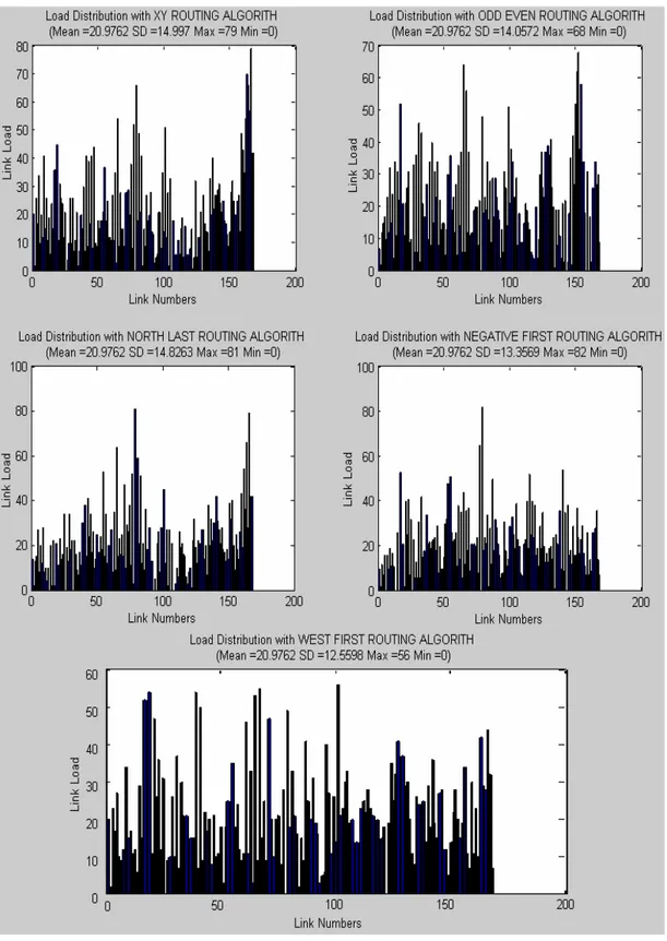
4.4.3 Link Load: Performance Parameter used for Evaluation ...39
4.5 EXPERIMENTAL SETUP IN MATPCTOOL...40
4.5.1 Selection of Communication Density ...40
4.5.2 Setup for Local Traffic ...40
4.5.3 Selection of Hot Spot Nodes for Hot Spot Traffic...41
4.5.4 Setup for Random, East Dominated and South Dominated Traffics...42
4.6 COMPARISON OF ROUTING ALGORITHMS FOR DIFFERENT TRAFFICS:RESULTS...43
4.7 ALGORITHM SELECTION FOR SPECIFIC APPLICATION TRAFFIC...47
4.8 PATH IMPROVEMENT...48
4.8.1 Algorithm 1: Constructive Path Computation Algorithm ...48
4.8.2 Algorithm 2: Iterative Path Improvement Algorithm ...50
4.8.3 Improved Paths for Source Routing: Results...51
4.9 PATH ENCODING...56
4.9.1 2-Bit Clockwise Router Port Address Encoding...56
5 Performance Evaluation of Source Routing... 59
5.1 ANALYTICAL ANALYSIS OF SOURCE ROUTING...59
5.1.1 Packet Delay Model ...59
5.1.2 Flit Delay Model...61
5.2 MODELLING AND SIMULATION REQUIREMENTS OF SOURCE ROUTING FOR NOC...61
5.2.1 Language Selection for Modelling ...62
5.2.2 Assumptions Made in Development of Simulator...62
5.2.3 Simulator Input Requirements and Specification ...63
5.2.4 Simulator Output Requirements and Specification...66
5.3 NOCSIMULATOR DESIGN FOR SOURCE ROUTING...67
5.3.1 Design and Simulation Tool...67
5.3.2 Top Level system Description of Simulator ...68
5.3.3 Integration of NoC Simulator and Matlab Based Path Computation Tool for Source Routing ...69
5.4 SIMULATION ANALYSIS OF SOURCE ROUTING...69
5.4.1 Performance Parameters Used for Evaluation ...69
5.4.2 Definitions of Some Parameters Used in Simulation ...69
5.4.3 Simulation Setup ...71
5.5 SIMULATION RESULTS...71
Table of Contents
6 Source Routing for NoC: Hardware Design Decisions... 80
6.1 NETWORK DESIGN ASSUMPTIONS...80
6.2 FLITIZATION...81
6.2.1 Packet Format ...81
6.2.2 Flit Type...82
6.2.3 Flit Format...82
6.3 DEFLITIZATION...84
6.4 RNIINTERNAL BLOCKS AND CONTROL SIGNALS...85
6.4.1 RNI I/O Buffers and Counters...86
6.4.2 Flitizer and Routing Tables...87
6.4.3 Deflitizer ...87
6.4.4 RNI Controller...87
6.5 ROUTER INTERNAL BLOCKS AND CONTROL SIGNALS...88
6.5.1 I/O Buffers ...89
6.5.2 Counters and Flags for Back Pressure Based Flow Control ...89
6.5.3 Cross Bar ...89
6.5.4 Switch Control ...90
6.6 2-BIT CLOCKWISE ROUTER PORT ADDRESS DECODER...90
6.6.1 Right Rotation of Route Information...91
7 Conclusions ... 93
7.1 SUMMARY OF CONTRIBUTIONS AND RESULTS...93
7.1.1 Algorithms for Computing Paths for Source Routing ...93
7.1.2 Summary of Tools for Source Routing ...93
7.1.3 Summary of Results ...95
7.2 LIMITATIONS AND FUTURE WORK...95
7.2.1 Limitations ...95
7.2.2 Future Work...95
8 References... 97
9 Appendix ... 99
9.1 LATENCY GRAPHS OF VARIOUS ROUTING ALGORITHMS FOR SOURCE ROUTING BEFORE AND AFTER PATH IMPROVEMENT...99
9.1.1 Using Random Application Specific Traffic ...99
9.1.2 Using South Dominated Traffic ...102
9.1.3 Using East Dominated Traffic ...105
9.2 THROUGHPUT GRAPHS OF VARIOUS ROUTING ALGORITHMS FOR SOURCE ROUTING BEFORE AND AFTER PATH IMPROVEMENT...108
9.2.1 Using Random Application Specific Traffic ...108
Introduction
1 Introduction
1.1 System on Chip
A rapid progress in Very Large Scale Integration (VLSI) in the past recent years has resulted in the fabrication of millions of transistors on a single silicon chip. With the current CMOS technology it is possible to implement a design with approximately one billion transistors on a single chip. This advancement in the micro-electronics leads to the integration of various components of a computing system or any other electronic system on a single Integrated Circuit (IC) to implement a complete system on a chip. Thus a paradigm called System on Chip (SoC) came into existence that refers to the system made up of interconnected cores or Intellectual Property (IP) block on a single chip.
1.1.1 Chip Capacity
Development of a complete system on a single chip became possible due to advancement in chip capacity which is the number of transistors that can be fabricated on the chip. Increase in chip capacity has been following the trend given by Moore’s law i.e. the chip capacity doubles every 18 months approximately. This law has been holding for over 40 years.
1.1.2 Core Based Design
In order to shorten the time to market, time to test and exploit reuse, mostly SoCs are designed with cores or IPs [20]. A core can be a general purpose processor, a DSP, a memory block, an application specific hardware component, an I/O controller, a Graphic Controller, a mixed signal module, a Radio Frequency (RF) unit etc. A designer can build a SoC by developing own cores or reusing Commercial off-the shelf (COTS) cores, available from different IP vendors, and finally interconnect them on a single chip [3]. An example of core based system design is the 80-core processor built recently by Intel as part of their research project [21].
1.1.3 Limitation of Buses and Interconnections
Nowadays, direct interconnections and mostly shared busses are used for on-chip communication [16]. The problem with direct interconnections is that they are not scalable and become inefficient with an increase in the number of cores. Shared buses do not scale beyond 8 to 10 cores. Contention for the bus and arbitration also slows down the data movement. They are only good for low communications.
In order to build a system on chip with large number of communicating cores, a new design solution, other than direct interconnections and shared busses, is required that provides communication among the cores.
Introduction
1.2 Network on Chip
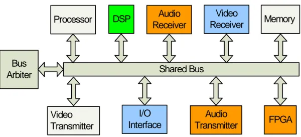
Network on Chip (NoC) is being considered as the most suitable candidate for implementing interconnections in core based system on chip (SoC) design [7]. In NoC paradigm, cores are connected to each other through a network of routers and they communicate among themselves through packet-switched communication. The protocols used in NoC are generally simplified versions of general communication protocols used in data networks. This makes it possible to use accepted and mature concepts of communication networks such as routing algorithms, switching techniques, flow and congestion control etc. in NoC. It allows significant reuse of resources and provides highly scalable and flexible communication infrastructure for SoC design [2]. Cores in a NoC operate in Globally Asynchronous, Locally Synchronous (GALS) mode. A SoC with NoC communication infrastructure is shown in Figure 1-1.
Processor Video Receiver Audio Receiver FPGA Memory DSP Video Transmitter I/O Interface Audio Transmitter
Network Interface Switch
Graphic Controller
Memory
Processor Core
Figure 1-1. SoC based on NoC communication infrastructure
1.3 NoC Design Issues
Performance of a NoC depends on many factors. Three main factors are discussed below.
1.3.1 Topology
Topology is a very important feature in the design of NoC because design of a router depends upon it. Different topologies are proposed in the literature for the design of NoC. Commonly used topologies are mesh, ring, torus, binary tree, bus and spidergon. Some researchers have also proposed topologies
Introduction Node Node Node Node Node Node Node Node Node Node Node Node Node Node Node Node Node Node Node Node Node Node Node Node Node Spidergon Network Mesh Network
Application Specific Network
Node Node Node Node Node Node Torus Network Node Node Node Node Node Node Node Node
Figure 1-2. Different topologies used in NoC 1.3.2 Core Selection
Core selection is an important step in the design of a NoC. Usually NoC is designed with a fixed size of tile slot. Therefore, a selected or designed core must fit in this slot. Some researchers have proposed the concept of “Region” to accommodate cores of different sizes [24]. Moreover, cores in NoC may be homogenous or heterogeneous. As compared to heterogeneous, homogeneous cores are all exactly the same having same size, instructions sets, equivalent clocks and they perform same functions. Although NoC with heterogeneous cores becomes complex, it may be relatively more efficient in terms of performance, power and thermal efficiency [22].
1.3.3 Routing Algorithms and Router Design
Communication performance of a NoC depends heavily on the routing algorithm used. Routing methods can be classified into two types, namely, source routing and distributed routing. In source routing, a source core pre-computes the information about the whole path from the source to the destination; selects this information for a desired communication and provides it in packet header. In distributed routing, the header contains destination address only and the path is computed dynamically by participation of routers on the path [5][10][11]. Design of a router also depends upon the type of routing. For example, router design for source routing will be simpler as compared to the router designed to handle distributed routing algorithm.
Introduction
A very large number of routing algorithms have been proposed in literature [12][13][14]. All the proposals so far fall under distributed routing type. Source routing has not been considered so far for NoCs, due to its apparent large overhead to store path information in the packet header. Since the paths in source routing are pre-computed offline, therefore source routing can provide no or limited path adaptivity in the case of faults and traffic congestion. In spite of these disadvantages, we feel source routing has many advantages over distributed routing.
1.4 Thesis Objectives and Tasks
The goal of this Master thesis is to develop and evaluate source routing for mesh topology NoC. In order to achieve this objective, first step is to perform general and analytical analysis of source routing and compare it with its competitor i.e. distributed routing. After that, a method should be developed to compute paths from source to destination for both general and application specific communications. The method should be able to identify the best routing algorithm for each type of selected traffic on the basis of link load utilization.
The paths should also be improved to provide uniform link load distribution. An efficient encoding scheme should be developed to encode paths for source routing. Then a simulator should be developed that can simulate source routing for mesh topology NoC. Using simulator, performance of source and distributed routing should be analyzed and compared. Similarly, performance of source routing alone should be analyzed for various routing algorithms in different traffics. Although router design is not part of this thesis, still NoC architecture based on source routing is developed and corresponding design decisions are also made.
1.5 Thesis Layout
In this chapter, we gave a brief introduction to the area in which this thesis is carried out. We gave a glimpse of NoC paradigm, its design issues, types of routing and routing algorithm used in NoC. We also discussed our motivation to use source routing in NoC. Finally, objectives of the thesis were discussed. Next chapter provides the reader with detailed background knowledge about NoC including its evolution, the concepts which it borrows from communication networks, its main components, existing NoC proposals, routing algorithms used and the parameters used to evaluate its performance. In chapter 3, we illustrate source routing with an example, present its advantages and disadvantages and perform its analytical comparison with distributed routing. Moreover, the issues and tasks required to implement
Introduction
In chapter 4, a method to compute paths for source routing is described by utilizing some standard distributed routing algorithms. Selection of the best routing algorithm for a specific traffic is also discussed in this chapter. We also present constructive and iterative methods to improve the computed paths. An efficient scheme to encode the paths is also described.
Chapter 5 focuses on the performance evaluation of source routing for mesh topology NoC. This evaluation is performed using a NoC simulator and results are presented and analyzed for various routing algorithms in different traffic patterns. Accordingly, specification requirements, modelling and development of this NoC simulator are also discussed.
In Chapter 6, we present mesh topology NoC architecture based on source routing. Apart from that we also make decisions that are required to design corresponding router and network interface. Chapter 7 concludes by listing summary of the contributions and results and our plan for future work in this area.
Network on Chip
2 Network on Chip
This chapter discusses theoretical background about the area of NoC. Discussion will start with the evolution of on-chip packet switched networks and continue with concepts borrowed from communication networks, main components of NoC, existing NoC proposals and types of routing algorithms used. The discussion will end with details of performance parameters used for evaluation of NoC.
2.1 Evolution of On-Chip Packet Switched Networks
2.1.1 Point to Point Connections
Very first way to design communication infrastructure for on-chip systems was to use direct point to point interconnection among system cores. This allows the cores to communicate directly through dedicated wires without any need of centralized arbitration. For a system with large number of cores, this communication design requires a lot of pins for each core, large routing time, large routing area and becomes very messy in terms of wiring.
Similarly, delays and quality of signals become unpredictable in the system when direct interconnections are used for communication. This makes it very difficult to test the system. Due to these disadvantages, point to point interconnection infrastructure exhibits poor scalability, low utilization of routing resources and very low possibility of reuse. On the other hand, a SoC designed with small number of cores based on this type of interconnections is likely to give highest possible performance [7]. A SoC designed with point to point connections is shown in Figure 2-1.
Processor
Video
Receiver
Audio
Receiver
Memory
DSP
Video
Transmitter
I/O
Interface
Audio
Transmitter
Network on Chip 2.1.2 Bus Based Integration
Inter-core communication of majority of SoCs is designed with bus based communication infrastructure. In this type of communication, all cores share one or more busses. Cores are connected to the bus through an interface. A bus arbiter manages the communication and contention among cores. In bus based design, cores require less number of I/O pins compared to direct interconnections. Similarly cost and area of wiring required for communication is also reduced.
In literature, there are many proposals for efficient use of buses such as hierarchical, segmented, pipelined buses etc. Despite these efficient proposals and above mentioned advantages, shared buses do not scale beyond a certain limit depending upon the number of cores. Moreover, contention for the bus and arbitration also slows down the data movement.
Processor DSP Audio Receiver FPGA Bus Arbiter Video Receiver Video Transmitter I/O Interface Audio Transmitter Shared Bus Memory
Figure 2-2. SoC based on shared bus communication infrastructure 2.1.3 Packet Switched Network Based Integration
Because of a number of disadvantages of direct interconnections and shared buses including low scalability, non adaptivity to new applications and very less or no reuse; a new method is required for inter-core communication in on-chip systems. Researchers proposed to use packet switched network for designing communication among cores in SoCs [1][2][5][6][7][ 8].
A packet switched network consists of a network of switches also called routers. Resources in the network are connected to the routers through resource network interface. Data moves from source to destination in the form of formatted packets traversing through one or more routers in the network. This type of on-chip communication infrastructure is highly scalable. It also provides high possibility of reuse, thus reducing time to market and cost of the system.
Network on Chip
Packet switched communication infrastructure for on-chip system is shown in
Figure 2-3. Similarly, a SoC based on 3X4 mesh topology NoC is shown in Figure 1-1.
Packet Switched
Network
Processor DSP Audio Receiver Video Receiver Video Transmitter I/O Interface Audio Transmitter Memory FPGAFigure 2-3. SoC based on packet switched network communication infrastructure
2.2 Existing NoC Architecture Proposals
A large number of different NoC architectures have been proposed by different research groups [1][2][16]. Topology, routing algorithm, packet structure and communication protocol stack are the important features which distinguish various NoC proposals. An on-chip architecture called Scalable, Programmable, Integrated Network (SPIN) has been proposed by Guerrier and Greiner [25]. They also proposed Fat-tree topology because of its lower network diameter and efficient VLSI layout. It implements message passing communication model [7].
Benini and De Micheli proposed packet switched micro-networks based communication infrastructure for SoC design [8]. Similarly, Network on Silicon is proposed by Philips research Laboratory. They propose to design SoCs based on communication network to support guaranteed throughput for real time traffic and best-effort communication for rest of the traffic. Another proposal called Linköping SoCBUS combines the advantages of circuit switched communication with those of packet switched communication. Another group of researchers developed KTH-VTT, a two dimensional mesh topology based NoC architecture for developing large and complex SoCs [7].
Network on Chip
Survey of related literature tells us that a large number of researchers have proposed different packet switched network architectures for the design of inter-core communication infrastructure in SoCs.
2.3 NoC: Protocols and Concepts
The protocols used in NoC are generally simplified versions of general communication protocols used in data networks. Similarly most of the network communication definitions that are used in data communication networks are also applicable in NoC. Some of these concepts and definitions are discussed in the following subsections.
2.3.1 Layered Communication
Like general communication networks, NoC uses layered communication. Therefore, network architecture can be divided into different layers such as from bottom to top physical, data link, network, transport and application layer. A layer can be considered as a combination of soft or hard components performing same functionality. Each layer performs its task independent of other layers and provides services to the upper layer and gets services from the lower layers. The way a layer performs its function is hidden from other layers. Layers communicate with each other through standard interfaces. Each layer implements different set of rules called protocols.
Advantages of layered communication come at the cost of certain overheads. In NoC, mostly three layers are considered i.e. physical, data link and network layer. Transport and application layer issues are also addressed. This thesis concentrates mostly on the network layer issues. Few aspects of data link layer are also considered.
Physical layer deals with the actual transfer of data. It is responsible for clock signals for every connection, number of wires, control signals, electrical levels, medium of transfer etc. Data link layer is concerned with flit formation, node to node communication, error detection and correction, flow control, encoding scheme etc. Network layer performs packetization, routing of packets from source to destination, resource addressing, packet buffering, and congestion control. It is also responsible for providing quality of service by addressing the issues of latency, throughput, jitter etc [23].
2.3.2 Network Communication Definitions
Some commonly used network communication terms such as message, packet, flit and phit are addressed in this subsection.
Message
Network on Chip
Packet
A message may be divided into many packets. Each packet represents a data unit that can be transferred in the network independent of other packets of the same message. It contains enough information to traverse through the network and reach its destination. Normally, a packet has two parts; one to store control and routing information and is called header while the other part called payload stores data. Sometimes packets also contain a trailer indicating end of packet. A packet may be of fixed or variable size. A packet maybe broken down into smaller data units called flits.
Flow Control Digit (Flit)
A flit is a flow control digit. It consists of a constant number of bits. It fits the storage resources in the network switches.
Physical Transfer Digit (Phit)
It is the physical transfer digit. It is transferred as a unit across a channel between the routers. It can also be regarded as link width because it is equal to the number of wires for data transfer between two routers. Size of Phit may or may not be equal to the size of flit.
Example
Consider that a fixed packet size of 512 bits is used in NoC. Flit size is set to 32 bits as the resource in this network switches can store 32 bits. A packet can be broken down into 16 flits. If 32 wires are available between all neighbouring routers in the network then size of phit will be also 32 bits. But if only 16 wires are available then phit size will be 16 bits and each flit will then be transferred between the routers in two communication steps.
2.3.3 Switching Techniques
Switching techniques are used to move data from the input channel to the output channel of a router. Latency in the network mostly depends upon the switching technique used [9]. Some of the switching techniques are store and forward, circuit switching, virtual cut-through and wormhole switching.
In store and forward, also called packet switching, a complete packet moves from one router to the next. It has higher communication delay because a packet can only be forwarded when it is completely received. Moreover large buffer of at least equal to one packet size is required.
In circuit switching, an electrical path is established between source and destination before sending the data. The connection is released after the data
Network on Chip
In virtual cut-through switching, the router starts forwarding the packet as soon as header arrives and the destined output channel is idle. There is no need to wait for the complete packet arrival. But if destined output channel is busy then the switch has to store complete packet. Therefore buffer requirement in switches is at least one packet. In our work, we are using wormhole switching technique in NoC, therefore, it is described below under separate heading. Wormhole Switching
In wormhole switching, a packet is divided into flits. Flit is a flow control digit and is defined in the next subsection. There are generally three types of flits i.e. head, body and end. The head flit carries the control and routing information of a packet; body flits carry the payload and end flit contains payload as well as end of packet information.
In order to send data from a source to destination, a head flit is transmitted first followed by body and end flits. Routers in the way check the head flit and lock the path for the rest of flits of each packet. The path is unlocked by the end flit. So the flits in wormhole switching travel through the network in a pipelined fashion. Thus buffer required in routers is very small and can be as small as one flit. The flits appear to move through the network like a worm and hence the technique gets the name wormhole switching.
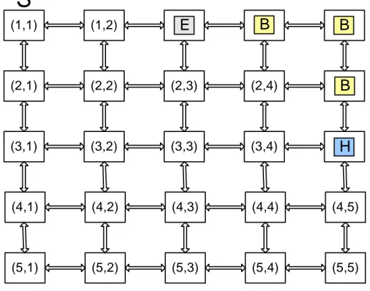
Consider an example in which a source “S” connected to node (1,1) sends a five flit packet to destination “D” at node (5,5). Router at node (1,1) decides to send the head flit “H” to node (1,2) depending upon the included routing information and the routing algorithm used. Route for rest of the flits is also locked by this router and the following flits will not be checked for deciding the route again. Similarly, head flit keeps on locking other routers and the rest of flits keep on following it in a pipelined manner. At some point in time, these flits are on their way to destination and are shown in Figure 2-4.
2.4 NoC: Main Components
There are three main types of components of a NoC namely routers or switches, cores also called resources and resource to network interfaces abbreviated as RNIs. These components are indicated in a 4X4 mesh topology NoC shown in Figure 2-5.
2.4.1 Resource
A resource can be a general purpose processor, DSP, memory, application specific hardware component, I/O controller, Graphic Controller, mixed signal module, Radio Frequency (RF) unit etc. Resources should be implementable by using the same technology as that of switch network [7]. A designer can build own resources or reuse Commercial off-the shelf resources available from
Network on Chip (1,1) (1,2) (2,1) (2,2) (2,3) (2,4) (3,1) (3,2) (3,3) (3,4) (4,1) (4,2) (4,3) (4,4) (4,5) (5,1) (5,2) (5,3) (5,4) (5,5)
E
H
B
B
B
S
D
Figure 2-4. Demonstration of wormhole switching in a 5X5 mesh topology NoC
2.4.2 Resource Network Interface (RNI)
RNI connects a resource to a network router. Hence it enables the resource to send data to the router. Purpose of RNI in NoC is the same as that of a network card in internet [7]. RNI consists of two parts i.e. resource dependent and resource independent as shown in Figure 2-6. Resource independent part is designed in such a way that RNI appears as another router to the connected router. Design of resource independent part is common for all resources. If homogeneous resources are used then resource dependent part can be reused and will be same for all resources otherwise it is different for every resource. Resource dependent part is responsible for flitization, deflitization and implementing encoding scheme. Encoding scheme will be discussed in chapter 4, whereas flitization and deflitization will be discussed in chapter 6. In case of source routing, RNI also contains routing tables and is responsible for adding complete path information in head flit.
Network on Chip DSP 1,1 Video Receiver 1,2 Processor 1,3 Audio Receiver 1,4 FPGA 2,1 Processor 2,2 Memory 2,3 Processor 2,4 DSP 3,1 Memory 3,2 Processor 3,3 DSP 3,4 Video Transmitter 4,1 I/O Interface 4,2 DSP 4,3 Audio Transmitter 4,4
Network Interface Switch
Figure 2-5. 4X4 mesh topology NoC with main components identified
R N I
R e s o u rc e In d e p e n d e n t P a rt R e s o u rc e D e p e n d e n t P a rt R o u te r R e s o u rc eNetwork on Chip 2.4.3 Router
Like in any other network, router is the most important component for the design of communication back-bone of a NoC system. In a packet switched network, the functionality of the router is to forward an incoming packet to the destination resource if it is directly connected to it, or to forward the packet to another router connected to it. Router implements layers of communication protocols below and including the network layer. It is very important that design of a NoC router should be as simple as possible because implementation cost increases with an increase in the design complexity of a router.
Main task of a router designed for distributed routing is to implement routing function. For an incoming packet, a route can be selected either by looking up a routing table already stored in the router memory or route can be computed dynamically by running a routing algorithm. A router that stores route tables and implements routing function by table look up is called table based router. Design of a router used for distributed routing can become complex as it requires extra logic and memory to implement routing function.
Router design for source routing will be quite different from the router designed to handle distributed routing algorithm. It does not need to select the output port for an incoming packet. The pre-decided information is available in packet itself. But it still needs to implement the other functions like packet buffering and arbitration using priority to resolve port conflicts when two or more packets require to use the same output port. The simplicity of a NoC router implementing source routing will make it run faster. Different types of NoC router architectures for distributed routing have been proposed by the researchers [2][3][4][16].
2.5 Classification of Routing in NoC
There are many ways to classify routing in NoC. Most commonly used classes are discussed in the following subsections.
2.5.1 Deterministic Vs Adaptive Routing
One way to classify routing in NoC could be deterministic or adaptive. In deterministic routing the path from the source to the destination is completely determined in advance by the source and the destination addresses. In adaptive routing, multiple paths from the source to the destination are possible. When a packet enters a router, destination address is read from the header and accordingly, the routing function computes all possible output ports where this packet can be forwarded to. Then a routing function selects one of the admissible output ports to forward the packet. The selectivity of output port depends upon the dynamic network conditions such as congestion and link faults. There also exist partially adaptive routing algorithms which restrict certain paths for communication. They are simple and easy to implement
Network on Chip 2.5.2 Minimal and Non-Minimal Routing
A routing which uses shortest possible paths for communication is known as minimal routing. It is also possible to use longer paths for data transfer from source to destination. This possibility results from the adaptivity offered by a routing algorithm. The type of routing which uses longer paths for communication although shortest paths do exist is known as non-minimal routing. Non-minimal routing has some advantages over minimal routing including possibility of balancing network load and fault tolerance.
2.5.3 Static and Dynamic Routing
In static routing, the path can not be changed after a packet leaves the source. In dynamic routing, a path can be altered any time depending upon the network conditions. Source routing is static while distributed routing can be static or dynamic depending upon the routing algorithm used. It should be noted that even when adaptive routing algorithms are used to compute paths for source routing, it remains static unless some sophisticated selection technique is introduced in the network.
2.5.4 Application Specific Routing
This type of routing is used for specialized applications or a set of concurrent applications. For a specific application of NoC based SoC in embedded systems we can have a good profile of the communications among different cores. This means that it is possible to know that which cores are communicating with each other and which cores do not communicate at all. In order to get best performance of NoC for a specific application, we can have specialized application specific routing algorithm. APSRA is one such algorithm [12][15].
2.6 Turn Model based Routing Algorithms for NoC
Communication performance of a NoC depends heavily on the routing algorithm used. A large number of distributed routing algorithms for NoC have been proposed in literature [12][13][14]. In this section we consider only turn model based routing algorithms which are used in mesh topology NoC. In this model certain turns are restricted for communication depending upon the rules used. Most important feature to be considered in a routing algorithm is deadlock freedom. All turn model based routing algorithms are deadlock free. Deadlock freedom followed by turn model based various routing algorithms are discussed in the following subsections.
Network on Chip 2.6.1 Deadlock Freedom
Deadlock is the process in which delivery of packets is delayed indefinitely because a set of packets are blocked in the network forever. One situation of deadlock is that a set of packets request for some network resources in a cyclic fashion at the same time when they are already holding some other resources in the network [9]. Wormhole switching technique is more prone to deadlocks compared to other switching techniques because a packet maybe holding buffer in many routers simultaneously.
One solution to avoid deadlock is to use priorities with the packets and allow pre-emptive communication. Similarly deadlock freedom can be guaranteed by the routing algorithm. One way to get a deadlock free routing algorithm in mesh topology is by restricting some turns as in the case of turn model based routing algorithms. Similarly, deadlock freedom can be achieved in other topologies by avoiding circular communications in channel dependency graphs [9].
Example of a Channel Deadlock
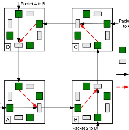
Consider four routers A, B, C, D. Router A has a packet “1” in its input buffer to be sent to router C. Similarly Routers B, C, and D have packets 2, 3, and 4 in their buffers destined for routers D, A and B respectively. Packet 1 cannot be transferred from router A to router B because buffer in the latter is occupied by another packet and waiting for another resource shown by dashed arrow in router B in Figure 2-7. Same is the case with rest of the routers. Thus, a situation is created in which each packet has occupied a buffer while requesting another buffer already being held by another packet. In this situation none of the packets is able to move and this results in a deadlock in the channel.
2.6.2 XY Routing Algorithm
It is one of the simplest and most commonly used routing algorithms used in NoC. It is a static, deterministic and deadlock free routing algorithm. Out of eight possible turns in mesh topology, XY routing algorithm allows half the turns by restricting rest of the half. According to this algorithm, a packet must always be routed along horizontal or X axis of mesh until it reaches the same column as that of destination. Then it should be routed along vertical or Y axis and towards the location of destination resource.
All possible turns that a packet can take in mesh topology NoC are shown in
Figure 2-8 (a).Similarly, restricted turns in XY routing algorithm are shown
with cross in Figure 2-8 (c). For a source located at node (1,1) and destination at (2,4) in a 4X4 mesh topology NoC, only one path is allowed using XY routing algorithm and is shown in Figure 2-9(a).
Network on Chip Buffer Input Selection Circuit Packet Progression Packet awaiting resource C D B A Packet 1 to C Packet 2 to D Packet 3 to A Packet 4 to B
Figure 2-7. An example of deadlock in channel involving four packets 2.6.3 Odd Even Routing Algorithm
It is a partially adaptive routing algorithm. It restricts East-North or East-South turn at any node located in an even column of mesh. Similarly in any odd column, it restricts the packets to take North-West or South-West turns. Restrictions in Odd Even routing algorithm are depicted in Figure 2-8 (b). Odd Even routing algorithm provides more even degree of adaptiveness compared to the rest of partially adaptive routing algorithms. For a source located at node (1,1) and destination at (2,4) in a 4X4 mesh topology NoC, allowed paths using Odd Even routing algorithm are shown in Figure 2-9(b).It should be noted that not all paths are allowed for this communication.
2.6.4 West First Routing Algorithm
It is also a partially adaptive routing algorithm. It restricts South-West or North-West turn at any node in the mesh network. It means that if a communication requires movement of a packet towards south along with any other direction, then the packet should be routed first towards south. Restrictions in West First routing algorithm are depicted in Figure 2-8 (d).
Network on Chip
West First algorithm restricts at least half of the source-destination communications to one minimal path, while rest of the pairs can communicate with full adaptivity. Hence, West First routing algorithm provides less even degree of adaptiveness compared to the Odd Even routing algorithm [13]. For a source located at node (1,1) and destination at (2,4) in a 4X4 mesh topology NoC, allowed paths using West First routing algorithm are shown in Figure
2-9(c). It should be noted that West First routing algorithm provides full
adaptivity by allowing all possible shortest paths for this communication.
Allowed Turns in Odd Even (Even Column) Allowed Turns in Odd Even (Odd Column) (b)
Allowed Turns in XY (c)
Allowed Turns in West First (d)
Allowed Turns in Negative First (e)
Allowed Turns in North Last (f)
8 Possible turns in mesh Topology NoC (a)
Network on Chip 2.6.5 Negative First Routing Algorithm
It is a partially adaptive routing algorithm. It restricts North-West or East-South turn at any node in the mesh network. It means that if a communication requires movement of a packet towards any negative axis, horizontal or vertical, along with any other direction, then the packet should be routed first towards that negative axis direction and in the end towards the other direction. Restrictions in Negative First routing algorithm are shown in Figure 2-8(e). For a source located at node (1,1) and destination at (2,4) in a 4X4 mesh topology NoC, Negative First routing algorithm provides no adaptivity and hence only one path is available for this communication as shown in Figure 2-9(e).
(1,1) (1,2) (1,3) (1,4) (2,1) (2,2) (2,3) (2,4) (3,1) (3,2) (3,3) (3,4) (4,1) (4,2) (4,3) (4,4) S D (1,1) (1,2) (1,3) (1,4) (2,1) (2,2) (2,3) (2,4) (3,1) (3,2) (3,3) (3,4) (4,1) (4,2) (4,3) (4,4) S D (1,1) (1,2) (1,3) (1,4) (2,1) (2,2) (2,3) (2,4) (3,1) (3,2) (3,3) (3,4) (4,1) (4,2) (4,3) (4,4) S D (1,1) (1,2) (1,3) (1,4) (2,1) (2,2) (2,3) (2,4) (3,1) (3,2) (3,3) (3,4) (4,1) (4,2) (4,3) (4,4) S (1,1) (1,2) (1,3) (1,4) (2,1) (2,2) (2,3) (2,4) (3,1) (3,2) (3,3) (3,4) (4,1) (4,2) (4,3) (4,4) S D D
(a) XY (b) Odd Even
(C) West First (d) North Last
Network on Chip 2.6.6 North Last Routing Algorithm
It is another partially adaptive routing algorithm. It restricts North-West or North-East turn at any node in the mesh network. It means that if a communication requires movement of a packet towards north along with any other direction, then the packet should be routed first towards the other direction and in the end towards north. Restrictions in North Last routing algorithm are shown in Figure 2-8(f). This algorithm restricts at least half of the source-destination communications to one minimal path, while rest of the pairs can communicate with full adaptivity. Hence, North Last routing algorithm provides less even degree of adaptiveness compared to the Odd Even routing algorithm. For a source located at node (1,1) and destination at (2,4) in a 4X4 mesh topology NoC, North Last routing algorithm provides full adaptivity by allowing all possible shortest paths for this communication as shown in Figure 2-9(d).
2.7 NoC Evaluation
2.7.1 Performance Parameters
Like other networks, performance of a NoC is evaluated by many parameters such as throughput, link load distribution, number of hops, latency, packet drop probability, fault tolerance, router area etc. Some of these parameters are discussed below.
Latency
It is the average delay required to transfer a packet from source to the required destination. In NoC, there are many factors that add to the latency including routing delay, channel occupancy, contention delay and overheads due to packetization and depacketization, flitization and deflitization, and synchronization among routers. Packet and flit latency models for a NoC based on source routing are discussed in detail in chapter 5.
Router Area
A routing algorithm in NoC can be evaluated on the basis of router size or area. A better routing algorithm will be the one whose router area is smaller and requires lesser hardware logic blocks.
Throughput
It is the total number of packets reaching their destination per unit time. Packet Drop
Network on Chip
Link load
Link load is defined as the amount of data flowing on each link in each direction provided the links are considered bidirectional. Network delay is heavily dependent on the link load and it increase exponentially with link load. Power Consumption
Power consumption has always been an important performance parameter in all types of networks. Routing algorithms in NoC are also evaluated on the basis of power consumed by the corresponding routers.
Fault tolerance
Fault tolerance is the ability of a routing algorithm to route packets in the presence of faults. It is a measure of number and types of faults tolerated by the algorithm.
In-order packet delivery
Another measure to check performance of a NoC is the in order delivery of packets. Out of order packet delivery results in extra functionality and cycles required in ordering packets at the destination and hence, it leads to lower network performance.
2.7.2 Traffic Generation
NoC performs differently for a typical routing algorithm using different types of traffic patterns [13][14]. Researchers have used a number of different traffic types for the evaluation of NoC [12][13][14][19]. These traffics include random, hot spot, transpose of type 1and 2, bit-reversal, shuffle, hot spot, application specific traffic etc. In this thesis, we will consider only five types of traffic for the evaluation of NoC and they are random, hot spot, east dominated, south dominated and west dominated. These traffics will be discussed in
Section 4.4.2. A tool will be developed in Matlab to generate these traffics.
Generation of these five traffics will be discussed in Section 4.5.
2.7.3 NoC Simulator
There are many simulators available which can be used to simulate NoC. Noxim is one such simulator that was developed in SystemC. It can simulate NoC using various distributed routing algorithms in different traffics. Limitation of Noxim is that currently, it does not support source routing. Similarly Network Simulator (NS2) can also be used for simulating NoC based on distributed routing. Like Noxim, it can also generate traffics and results automatically.
Network on Chip
As the existing available simulators do not support source routing for NoC, therefore, it is required to develop a new NoC simulator based on source routing. There are many options available for the selection of language for modelling NoC simulator such as SystemC, SDL, C/C++, Java etc. We selected SDL because it has already been used by our research group to model NoC simulator for distributed routing [3].
Source Routing: an Overview
3 Source Routing: an Overview
Like other networks, communication performance of a NoC depends heavily on the routing method used. Routing methods have been classified in literature in several ways. One way to classify them is source routing and distributed routing. In this chapter, we discuss source routing in detail, illustrate its use in NoC with an example and present its merits and demerits. Moreover, we also investigate source routing in NoC context and perform its analytical comparison with its competitor i.e. distributed routing. Finally we present the necessary steps required to implement source routing in NoC.
3.1 Introduction to Source Routing
In source routing the information about the whole path from the source to the destination is pre-computed and provided in packet header as opposed to distributed routing, where packet header contains destination address only and the path is computed dynamically by the participation of routers on the path [5][7][10]. With source routing, all routing decisions are made inside the source core before injecting any packet in the network. For this purpose, each source contains lists or tables that contain complete route information to reach all other resources in the network. Instead of storing tables in source, it is also possible to add extra logic or software in the source resources that implements any adaptive routing algorithm and dynamically computes paths for source routing.
In order to route a packet through the network using source routing, a sender resource consults its routing table to get a complete path to the required destination. This path is then written in the dedicated field in the packet header. The packet is transferred to the network through network interface. The packet must follow the path while traversing through the network towards its destination. Each router that receives this packet reads the path field in the packet header and forwards it to the destined output port. Unlike a router used in distributed routing, this router does not require any extra computation for making routing decisions because the packets already contain pre-computed decisions.
A very large number of routing algorithms have been proposed in literature [12][13][14][15]. All the proposals so far fall under distributed routing type. Source routing has not been so far considered for NoCs, due to its apparent large overhead to store path information in the header. Since, paths in source routing are pre-computed offline, therefore source routing can provide no or limited path adaptivity in the case of faults and traffic congestion. In spite of these disadvantages, we feel that source routing has many advantages over distributed routing and they will be discussed in detail in Section 3.3.
Source Routing: an Overview
3.2 Illustrative Example of Source Routing for Mesh
Topology NoC
In order to demonstrate working of source routing, consider an example of a 4X4 mesh topology network on chip as shown in Figure 3-1. Assume that a DSP processor connected to router (1, 1) wants to send a packet to a memory resource connected to the router (2, 3) as indicated by black arrow in the figure. Also consider that XY routing algorithm is used for this communication. Accordingly, the packet generated by DSP processor will traverse through routers (1, 1), (1, 2), (1, 3) and (2, 3) before reaching the destination memory resource. Thus the packet header will contain the address of all the routers traversed as shown in Figure 3-1. Similarly, Figure 3-2 depicts the packet format if distributed routing was used. The packet header contains only destination address instead of complete path.
DSP (Source) 1,1 Video Receiver 1,2 Processor 1,3 Audio Receiver 1,4 FPGA 2,1 Processor 2,2 Memory (Destination) 2,3 Processor 2,4 DSP 3,1 Memory 3,2 Processor 3,3 DSP 3,4 Video Transmitter 4,1 I/O Interface 4,2 DSP 4,3 Audio Transmitter 4,4
Network Interface Switch
Figure 3-1. Illustrative example of source routing for a 4X4 mesh topology NoC
S ource R outing P acket F orm at
P ath 1 ,1 P acke t 1 ,2 1,3 2 ,3 2 ,3 P a cke t D e stina tio n A d d re ss
D istribute d R ou ting P acket F orm at
Source Routing: an Overview
3.3 Advantages and Disadvantages of Source
Routing
In this section, we discuss advantages and disadvantages of source routing when it is used in both general communication networks and on-chip networks.
3.3.1 Advantages
Source routing is not perhaps suitable for dynamic networks where network size and topology are changing. But in a NoC with fixed size and regular topology like mesh, the path information can be efficiently encoded with small number of bits. It can be easily shown that two bits are sufficient to encode every hop in the path. We feel that the following advantages of source routing [5][9][11] more than compensate its disadvantages.
1) Speed
The foremost advantage is speed. Once a path is selected from the table and included in the packet header inside source, no further time is spent in routing. As each packet arrives at a router, it can immediately select its output port from pre-computed path information in the packet header without any computation or memory reference. Thus, a router used for source routing is faster than that used for distributed routing.
2) Simpler and Smaller Router Design
Since the packet entering a router contains the pre-computed decision about the output port, there is no need for any routing logic or tables in the router and hence, the router design is significantly simplified and its implementation will also be less costly.
3) Topology Independence
Source routing is topology independent. It can route packets in any connected topology provided it does not change dynamically. It should be noted that this advantage of source routing is limited by the number of router ports, the size of the source table and the maximum length of a route.
4) Mixed, Minimal and Non-minimal Routing
In case of source routing, non minimal routing advantage can be applied. Non minimal routing offers a number of advantages such as link load distribution, congestion control and fault tolerance. Source routing also provides possibility of mixing minimal and non-minimal paths.
Source Routing: an Overview
5) Scalability
Since only a constant number of bits of the header are used in every router, its design is not only simple but also independent of the network size. Routers that use source routing can be used in arbitrary-sized networks because all the limitations on network scalability including network size, source table size, and route length are determined by the source. We feel this to be a major advantage over distributed routing where destination address field will depend on network size and topology.
6) Ease of Changing Paths
In source routing, there is a possibility of changing paths very easily as path table is stored in memory of the source. The paths can even be changed dynamically.
7) Property of Load Distribution
Since NoCs used in embedded systems are expected to be application specific, we can have a good profile of the communication traffic in the network [12]. This allows us to analyse the traffic and compute offline, efficient paths giving the desired performance characteristics, like uniform link load distribution. On the other hand in distributed routing, some extra logic is required in the routers to keep the status of the neighbouring router ports for the purpose of load balancing and it is very hard to distribute link load uniformly when distributed routing is used.
8) No Problem of Live Lock
Live lock is the situation in which a packet keeps travelling in the network and never reaches its destination. There is no problem of live lock in source routing. A packet takes finite number of hops before reaching its destination because of the fixed length source route. Live lock may be a problem with some distributed routing algorithms but it can be avoided with careful construction of routing tables.
9) Guaranteed Throughput
Source routing is better when guaranteed throughput is required especially in the case of real time traffic. This can be achieved by assigning “special paths” to such communication.
10) In-Order Delivery of Packets
The single path for each pair in the network avoids out of order packet delivery problem that is exhibited by adaptive routing algorithms.
Source Routing: an Overview
11) Good for Troubleshooting a Network
Source Routing can also be used to troubleshoot a network. If any link in the network is broken or any router is down, then test packets are sent to all destinations using source routing. Upon receiving test packets, destinations reply by sending response packets to the sender. Faulty link or router can be identified easily by performing the analysis of the response packets received.
3.3.2 Disadvantages
All the above mentioned advantages of source routing come at the cost of a number of disadvantages which are discussed below in detail.
1) Routing Overhead
In source routing, a packet must carry the routing information in the packet header thus increasing the size of packet. Packet header in source routing is larger compared to that of distributed routing.
2) Static and Non-Adaptive Nature of Source Routing
Source routing is static in nature. This means that the path cannot be changed after the packet has left the source unless some sophisticated techniques are used. Source routing does not take into account the current traffic pattern in the network. Although some sort of adaptivity may be introduced by keeping more than one path to every destination in the source tables still source routing cannot achieve adaptivity. Moreover, source routing is unable to work in the presence of faults in the network unless some fault tolerance is introduced. 3) Limitation of the Size of Source Table
In source routing there is a limitation of the size of source table. Storing large tables in sources may become a cost, size and performance overhead for resources, especially for resources which are not of processor type.
4) Scalability
In source routing, there is a limitation of the maximum length of the route i.e. the path may not fit in the flit unless some special technique is used. The technique should allow variable size path information. This will increase path overhead and complexity of decoding logic.
Source Routing: an Overview
3.4 Analytical Analysis of Source and Distributed
Routing for NoC
In this section we perform analytical analysis of source and distributed routing. This analysis is focussed on the routing overhead, bandwidth utilization and router delay.
3.4.1 Overhead
As complete route information along with the payload should be stored in a packet in case of source routing, large underutilization is expected. But analytical comparison between source and distributed routing eliminates this fear of underutilization. Figure 3-3 shows a graph plotted for the number of bits required for routing against different size of square mesh NoC for both source and distributed routing. It is clear that with source routing, number of routing bits increases proportional to the diameter of the network (that is square-root of the size of the network). On the other hand, routing bits required for distributed routing increase logarithmically with the network size. The gap between the two graphs keeps on increasing with an increase in the size of NoC and thus apparently making source routing look unusable in practice. For both types of routing, the bits required to route data in a NXN mesh NoC is given by the following formulae.
Number of routing bits in Distributed Routing = 2*⌈ log2 (N) ⌉
Number of routing bits in Source Routing = 2(2N-1)
But, if the overhead is measured in terms of extra flits to be communicated, the difference is very small or zero. We analyse this in the next sub-section
Source Routing: an Overview 3.4.2 Bandwidth Utilization
We get a different view of the comparison between source and distributed routings in NoC when bandwidth utilization is considered. Bandwidth utilization is defined as the ratio of the payload in bytes to be transmitted and the actual number of bytes to be sent carrying this payload as shown in the following equation.
When wormhole switching technique is used in NoC, the data is transferred in the form of flow control digits called flits. We consider fixed size flit equal to four bytes. Chapter 6 can be referred for further details of flit. In case of source routing, a head flit carries the complete route information and we assume that it does not carry any payload. In case of distributed routing we consider that a head flit can carry maximum of two bytes of payload. Let “P” be the payload in bytes to be transmitted. Based on these considerations, actual number of bytes to be sent carrying payload “P’ in case of source and distributed routing is given by the following formulae.
Actual No. of bytes required in Source Routing = 4 + 4*⌈(P/4)⌉ Actual No. of bytes required in Distributed Routing = 4; for P = 1, 2
Source Routing: an Overview
In Figure 3-4, utilization is plotted against the payload in bytes to be routed for both source and distributed routing for a 7x7 mesh topology NoC. It can be seen that with less number of bytes in payload, both source and distributed routing show very less utilization and relatively bigger gap between the two. By increasing the number of bytes in payload, utilization of both routings increases while the gap between them becomes smaller. There exists a correlated trend of increasing utilization with increasing payload in both types of routing. For larger payloads, utilization of both types of routing becomes very close to each and near to 1, thus making source routing as good as distributed routing. This quality of source routing was not evident from the analysis of Figure 3-3.
3.4.3 Router Delay
Router logic delay “TRL” is a very important factor to be considered when
source and distributed routings are compared analytically. TRL is the time
required to transfer a flit from the input buffer to the output buffer of a router. It depends upon the time required to decode flit type and routing information, selection of output port and switching activity inside the router. As opposed to source routing, routing tables are consulted in each router in distributed routing thus, creating an extra delay of at least one router clock. In case of source routing, complete path information is already present in the header flit; therefore routing logic is simpler, faster and smaller compared to distributed routing.
3.5 Steps for Designing NoC with Source Routing
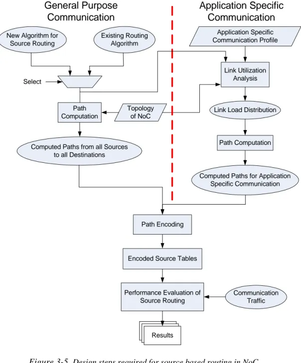
Design of complete source routing scheme involves a number of steps including algorithm selection for source routing, computation of path for each communication, uniform distribution of link load and path improvement accordingly, encoding of the computed paths, simulation analysis of source routing and finally design of a router as shown in Figure 3-5. Rest of this thesis report follows and investigates the steps depicted in Figure 3-5 in detail. Only main steps are briefly described in the following sub-sections.
3.5.1 Algorithm Selection and Path Computation for Source Routing
First step in designing source routing is to make decision that whether an exiting routing algorithm will be used or a new algorithm will be developed for path computation. Once the decision is made, then paths should be computed for each source to every destination depending upon the selected communication i.e. general purpose or application specific. In application specific case where a complete communication profile is available, analysis for link load distribution is performed before computing final paths by exploiting the adaptivity of the routing algorithm used. Path improvement algorithms can
Source Routing: an Overview 3.5.2 Path Encoding
Once path from source to destination is computed, it should be encoded in the packet header. Path encoding should be done in such a way that the overhead of routing information is minimized. Moreover, path encoding should be such that it is easy to decode in the routers on the way to the destination. In order to minimize the route information overhead in the head flit, we have used 2-bit clockwise router port address encoding scheme. This path encoding scheme will be discussed in Section 4.6.
Link Utilization Analysis Communication Traffic Application Specific Communication Profile
Computed Paths from all Sources to all Destinations
Existing Routing Algorithm New Algorithm for
Source Routing
Path Computation
Path Encoding
Encoded Source Tables
Performance Evaluation of Source Routing Results Select Topology of NoC
Link Load Distribution
Computed Paths for Application Specific Communication Path Computation General Purpose Communication Application Specific Communication