Postadress:
Besöksadress:
Telefon:
Concept
develop-ment of roof
mounted bike carrier
PAPER WITHIN: Product development AUTHOR: Matilda Lundberg & Linus Tjörnevik TUTOR:Samuel André
Postadress:
Besöksadress:
Telefon:
This exam work has been carried out at the School of Engineering in Jönköping in the subject area product development. The work was a part of the three-year Bachelor of Science in Me-chanical Engineering program.
Examiner: Joel Johansson Supervisor: Samuel André Scope: 15 credits (first cycle) Date: 2017-05-22
Abstract
This thesis has resulted in a concept- and prototype development of a new car roof mounted bike carrier. The design problem was assigned by Thule Group and was intended be performed alongside the company’s own project of updating their different roof mounted carriers. What Thule wanted to gain from this project was to obtain concepts produced with a different ap-proach than their usual course of action. This could lead to concepts consisting of solutions not before thought of.
The solution should answer to three major problems: 1. How the bike could be attached to the carrier. 2. How the mechanism could tighten.
3. How the user could be given feedback when enough force had been applied.
This report explains the approach to the problem and how the used design process has been implemented. The solution to the problem are presented successively of how the front holder of a bike carrier is developed, from idea into prototype. The applied design process “Produkt-utveckling - Effektiva metoder för konstruktion och design” have an iterative structure. An it-erative process does not occur in a straight line, but rather in a spiral that repeat its steps over and over again to achieve better results.
The different phases and methods of the design process are explained to clarify the approach of the implementation. These methods includes Benchmarking, User study, Quality function de-ployment, 6-3-5 Brain writing method, PUGH and Validity and Reliability. To give this thesis a theoretical foundation, theories about the design process, semantics and intuition been applied. The generated ideas resulted in two concepts that were further developed and presented. One of the concepts was decided by Thule to undergo a patent research, which was not completed before this thesis was finished. This concept has therefore not been explained in detail. The other concept has been presented in its complete state, explaining its solutions to the design problem.
The report explains all features the prototype of the product resulted in. The design process is presented in a chronological way and contribute with an easy traceability throughout this re-port.
Sammanfattning
Denna avhandling resulterade i framtagningen av koncept och prototyp till en ny biltakmonte-rad cykelhållare. Designproblemet utfordbiltakmonte-rades av Thule Group och var menat att utföras i sam-band med företagets egna projekt att uppdatera alla deras takmonterade cykelhållare. Thule ville att detta projekt skulle bidra med koncept som var framtagna med ett tillvägagångssätt som skiljde sig från deras utvecklingsprocess. Målet var att det skulle skapa koncept som inne-höll nya lösningar som Thule inte tidigare tänkt på.
Lösningen skulle besvara tre större problem: 1. Hur cykeln kan fästas vid hållaren. 2. Hur mekaniken ska kunna spännas åt.
3. Hur användaren ska ges feedback när tillräcklig inspänningskraft har tillämpats. Denna avhandling förklarar hur problemet har angripits och hur den valda designprocessen har implementerats. Lösningen presenteras stegvis där den främre delen av cykelhållaren tas fram och genomgår stadier från idé till prototyp. Den följda produktutvecklingsprocessen “Produkt-utveckling - Effektiva metoder för konstruktion och design” har en iterativ struktur vilket bety-der att vissa steg i processen har upprepats för att skapa bättre resultat.
Designprocessens olika faser och metoder är beskrivna för att tydliggöra hur tillvägagångssättet över användningen av dessa har implementerats. Konkurrensanalys, användarstudie, QFD, brainstorming, PUGH och validitet och reliabilitet är alla metoder som denna avhandling be-handlat. Den teoretiska grunden kommer från teorierna om produktutvecklingsprocessen, se-mantik och intuition.
De framtagna idéerna resulterade i två slutgiltiga koncept som togs vidare för vidareutveckling. Ett av de två koncepten ansågs av Thule ha en nytänkande lösning och det bestämdes att pati-entundersökning av denne skulle genomföras. Eftersom undersökningen inte blev klar innan avhandlingens avslut är designlösningen av detta koncept inte förklarat i detalj. Det andra kon-ceptets designlösning har det tagits fram en fungerande prototyp av där den mekaniska lös-ningen är presenterad.
Contents
1
Introduction ... 1
1.1 BACKGROUND ... 1 1.1.1 Company ... 1 1.1.2 Design problem ... 1 1.2 STATEMENT ... 21.3 OBJECTIVE AND RESEARCH QUESTION ... 3
1.4 DELIMITATIONS ... 3
1.5 OUTLINE... 3
2
Theoretical background ... 4
2.1 CONNECTION BETWEEN RESEARCH QUESTION AND THEORETICAL BACKGROUND... 4
2.2 PRODUKTUTVECKLING -EFFEKTIVA METODER FÖR KONSTRUKTION OCH DESIGN ... 4
2.2.1 Pilot study... 4
2.2.2 Requirement specification ... 4
2.2.3 Concept generation... 4
2.2.4 Concept elimination ... 5
2.2.5 Configuration and detail design ... 5
2.2.6 Prototypes ... 5
2.2.7 Adapt for manufacturing ... 5
2.3 CUSTOMIZED DESIGN PROCESS ... 5
2.4 SEMANTICS ... 6
2.5 INTUITION... 6
3
Method ... 7
3.1 CONNECTION BETWEEN RESEARCH QUESTION AND METHOD ... 7
3.2 CONCEPT STUDY ... 7
3.3 PILOT STUDY ... 8
3.3.1 Benchmarking ... 8
3.4.1 6-3-5 Brain writing Method ... 9
3.4.2 Quality Function Deployment (QFD) ... 9
3.5 CONCEPT ELIMINATION ... 11
3.5.1 PUGH ... 11
3.6 VALIDITY AND RELIABILITY ... 12
4
Implementation and Result ... 13
4.1 PILOT STUDY ... 13
4.1.1 Project planning ... 13
4.1.2 Benchmarking ... 13
4.1.3 User study & Interview ... 13
4.1.4 Quality function deployment (QFD) ... 16
4.2 REQUIREMENT SPECIFICATION ... 17 4.3 CONCEPT GENERATION ... 17 4.3.1 Session 1 ... 17 4.3.2 Session 2 ... 18 4.4 CONCEPT ... 19 4.4.1 Concept 1 ... 19 4.4.2 Concept 2 ... 19 4.4.3 Concept 3 ... 20 4.4.4 Concept 4 ... 20 4.4.5 Concept 5 ... 21 4.5 CONCEPT ELIMINATION ... 21 4.5.1 PUGH ... 21
4.6 CONFIGURATION AND DETAIL DESIGN ... 21
4.6.1 Testing of the tightening force ... 21
4.6.2 Testing prototype ... 22
4.6.3 Input ... 24
4.6.4 Sprints ... 25
4.7 FINAL CONCEPTS ... 27
4.7.2 Concept 3 ... 27
5
Discussion ... 32
5.1 IMPLICATIONS ... 32
5.1.1 Research questions ... 32
5.2 VALIDITY AND RELIABILITY ... 33
5.2.1 Olesen’s five factors ... 33
5.2.2 Reliability ... 34
6
Conclusions and recommendations... 35
6.1 FULFILLMENT OF REQUIREMENT SPECIFICATION ... 35
6.2 RECOMMENDATIONS ... 35
6.3 EVALUATION OF DESIGN PROCESS... 35
6.4 FURTHER WORK ... 36
7
References ... 37
8
Attachments ... 38
8.1 ATTACHMENT 1,GANTT ... 38
8.2 ATTACHMENT 2,BENCHMARKING ... 39
8.3 ATTACHMENT 3,PICTURE OF THULE T-TRACK SYSTEM ... 40
8.4 ATTACHMENT 4,THULE THRURIDE 565 ... 40
8.5 ATTACHMENT 5,OBSERVATIONS FROM USER STUDY ... 41
8.6 ATTACHMENT 6,INTERVIEW FROM USER STUDY ... 42
8.7 ATTACHMENT 7,REQUIREMENT SPECIFICATION ... 45
8.8 ATTACHMENT 8,QFD ... 46
8.9 ATTACHMENT 9,PUGH ... 47
8.10 ATTACHMENT 10, SLIPPAGE TEST ... 48
8.11 ATTACHMENT 11, FRONT FORK ... 49
1
Introduction
This bachelor thesis consists of 15 credits and is embedded in the program of Mechanical En-gineering with orientation of Product Development and Design at Jönköping University. This thesis has been made in collaboration with Thule Sweden AB at their facility in Hillerstorp, Sweden.
The project that was specified by Thule Sweden AB consisted of the development and presen-tation of new concepts for the already existing roof mounted bike carrier, Thule Sprint XT. Fo-cus has been on the redevelopment of the mechanism on which the front fork attaches to. The objective was to present mock-ups and visualize the product’s functions.
1.1 Background
1.1.1
Company
Thule Sweden AB was founded 1946 by Erik Thulin and is a product developing and manufac-turing company, producing transportation equipment. They are the market leader in cargo car-riers but also a leading company in the outdoor market. Their goal is to bring people, whose passion in life is outdoor activities, closer to the nature. The products they produce all have the intention to enhance and improve the everyday life of active families and outdoor enthusiasts. The company’s beliefs lie within having an active lifestyle regardless of the environment you are in, whether it is city life or remote wilderness.
Thule Sweden AB is part of Thule Group, a company consisting of a collection of brands, all aimed at outdoor activities and transportation solutions. Thule Group is spread worldwide and have more than 4700 points of sales in 136 countries. Thule Sweden AB have their main office in Malmö, Sweden. Their testing Centre is located in Hillerstorp, Sweden, where they also have their production of roof racks as well as an in-house design department. [1]
1.1.2
Design problem
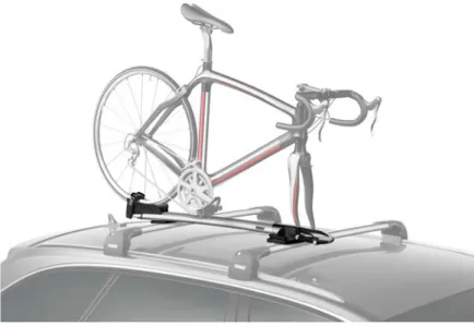
Thule Sprint XT is a car roof mounted bike carrier, included in the Thule Sweden AB assort-ment. The product is being sold worldwide and gives the user the possibility to mount their bike on the roof of the car, provided it is equipped with a pair of suitable roof racks. At the time of this thesis’s beginning, Thule initiated a project with the goal to update, improve and launch the next generation of roof mounted bike carriers. This resulted in the need of producing a new concept for development regarding the Thule Sprint XT. The current design of the front fork attachment were not considered to be optimal. This was because it consisted of many com-plexed components as well as having a mechanical solution resulting in oblique surfaces. To enhance the product, a new mechanical solution had to be developed. The solution should in-clude these three functions:
• Front fork attachment
• Tightening with equally distributed force • Give feedback when enough force is applied
Figure 2 Thule Sprint XT mounted unto a car with a bike
1.2 Statement
The majority of bike carriers on the market today are not offering any indicators for the user to understand when the bike is tightened with enough force. Regardless of the amount of experi-ence when it comes to mounting bikes onto carriers, the user is left in the dark considering how much tightening-force that is required. Consequently, the user could either attach the bike with too much force, endangering damaging it, or with too little force which could lead to the bike falling off. Thule Group has developed the Thule Sprint XT, which is the only rooftop fork holder bike carrier available on today’s market that provides force limitation feedback. This gives the user feedback of when the right amount of tightening-force has been applied.
Since the market constantly increases the demands on the products being launched, renewal and improvements are always necessary actions. An optimized solution is at all times of out-most interest. This is the reason for Thule to examine their current carriers and motivates the project of the new product launches.
The result that this thesis will provide regarding the product development process can be useful to other interests during their development. A product that does not possess enough quality or durability will have difficulties in competing in today’s market where high product standards have become a matter of course.
1.3 Objective and research question
The objective of this thesis was to perform a design process to develop new concepts for solving the mechanical construction in the front attachment point in a bike carrier. The solution to the problem is achieved when the given requirements in the specification are met [Attachment 7, Requirement specification].
This leads to the following research question:
How can the mechanism in the front holder of a bike carrier be de-signed, fulfilling a given requirement specification?
The research question will be answered when the following three questions are answered: 1. How can the bike be attached to the front of the bike carrier?
2. How can the force that is applied during fastening of the bike be equally distributed on both sides of the fork?
3. How can the user be given feedback when the right amount of force has been applied?
1.4 Delimitations
This thesis was focusing on developing new product concepts and doing this with appropri-ate methods and approaches of the concept developing phase in the design process. It will not consider the remaining steps in a complete product development cycle, such as adapting for manufacturing and product launch.
Because of time limitation, exhibition of a production-ready concept and prototype was not considered in this thesis. The goal has been to present mock-ups and visualize the product’s functions through CAD renderings, as well as simpler prototypes. Physical testing was only done to prove concepts but given standards and regulations have been embossed in the devel-opment since they, in practice, had to be met.
Estimations have been drawn through coarse calculations to verify the feasibility of the con-cepts. The choice of materials has not gone through thorough evaluations and investigations.
During concept generation, cost and production viability have been taken into account but no meticulous calculations have been done regarding it.
1.5 Outline
The thesis begins with the theoretical background, were the foundation to the theory that have been used during this thesis are explained. This will include the design process that were prac-ticed as well as some design knowledge such as semantics and intuition.
The method chapter explains the used methods and their relevance for this study. The methods are written in the order which by they have been implemented.
The approach to the design process and the outcome of the study is presented in the implemen-tation and result chapter. When reading this chapter, the reader will gain an understanding of how the product have been developed during the different phases. The final concepts with fea-tures and functions will here be presented.
This thesis ends with the conclusion and discussion chapter. The discussion includes implica-tions that this study could imply. The conclusions of the result, regarding the met requirements and research questions are presented. The thesis’s possibility of what further work that can be done to the project and its viability and reliability are discussed.
The last part of this thesis consists of the reference list and attachments. The attachments con-sist of picture, figures and other documents that did not fit in the thesis but will give information that could increase the understanding in some sections of the thesis.
2
Theoretical background
This chapter presents and refers to the theories that provides the study with a theoretical foun-dation. It begins with explaining how the presented theory are connected with the study’s re-search questions. Thereafter it continues with the describing of the theory behind the per-formed design process and ends with presenting a theory of semantic and intuition.
2.1 Connection between research question and theoretical
background
To give this thesis’s research question a theoretical foundation, a verified design process with its associated phases are presented. To allow needed process adjustments, a theory about cus-tomized design processes, called “Creativity, trust and systematic processes in product devel-opment” also will be given.
Apart from that, the theory about the design process will give a theoretical background to the subsequent questions as well, the theories about semantics and intuition will further establish this. These theories are described due to that the stages in the design process provides tools and methods to answer the questions. The theory behind semantics offers knowledge about how signs and design interacts with the user. The theory about intuition provides help for decision making during the entire development process.
2.2 Produktutveckling - Effektiva metoder för konstruktion och
design
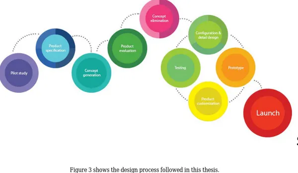
In the book Produktutveckling - Effektiva metoder för konstruktion och design [2], a design process is presented as shown in picture [Figure 3]. The presented process includes stages be-ginning with creating a strategic plan that will lead to innovation and end with the launching of a complete product. The authors state that this process is iterative and that the different stages could be performed repeatedly during the project. Depending on what kind of project that is performed the amount of stages differs. [2, p. 115]
2.2.1
Pilot study
During a pilot study a problem analysis is performed to gather background information that later can be used in a potential product development project. The analysis should be performed without any preconceptions and premature defined solutions to avoid limitation of innovations and creativity. To maintain an adaptable product development process and avoid unnecessary testing and design work, it helps to include a wide range of competence as early as in the pilot study. Resources are not prioritized during the pilot study nor the concept generating phase. However, a plan on how to distribute these resources in later stages of the project should be produced. [2, pp. 115-116]
2.2.2
Requirement specification
The intention of the product specification phase is to state a specification of what the design process should result in. This is done with the information collected in the previous phase. This should be applied in a way that creates a foundation for later attempts to find a design solution. It should also work as a reference when evaluations for these solutions are done and result in a final concept. Since the understanding and knowledge about the soon to be developed product increases during the design process, the specification will be developed and updated throughout the project. The specification should, in its final state, include all criteria from the explicit and implicit conditions stated in the early process, criteria developed during clarification of the task and those who occur after different design determinations. The criteria should be separated into two different groups. Those who are related to the expected functions of the product and those who limits the allowed solutions of the product. [2, pp. 117-118]
2.2.3
Concept generation
The authors state that the definition of the word concept is a first run-up of a solution. This kind of solutions includes a rough layout of the product, cost estimations, illustrations and
infor-not give enough conditions to enable creation of a working prototype, but will on the other hand generate ideas that will lead to the final concept. There are a range of different methods to gen-erate concepts, but the authors mention two categories as the main two. The first category is the creative methods which for instance includes brainstorming. The second category is called systematic and rational methods. [2, pp. 119-120]
2.2.4
Concept elimination
The concept elimination phase intends to analyze and compare the different solutions against each other and eventually select a concept to continue the process with. The evaluation should rank the concept’s values relative to the demands and requirements from the specification. The selection should be motivated by the concept that receives the highest rating during the analy-sis. Challenges could appear during this phase since different characteristics could be valued and measured differently by different stakeholders. Systematic matrices could be of great help during the selection. Evaluation of specific requirements could however be necessary. Actions such as rough calculations, testing of physical prototypes, modeling or computer aided simula-tions could in this case be performed. [2, pp. 120-122]
2.2.5
Configuration and detail design
With the previous phases as foundation, the selected concept will now be ready for further de-velopment to become a functional product that fulfill the requirements. This phase is focusing on the detail design of the selected concept. This includes: dimensioning, selection of standard parts, design and choice of material and definition of the layout. This phase should lead to a prototype capable of testing, describing the intended product functionality and usability. [2, pp. 122-124]
2.2.6
Prototypes
There are a lot of reasons for creating a prototype and the variety of appearances differs with the purpose behind the prototype. Today, virtual prototyping is a commonly used method for testing and visualizing both function, appearances and performance before any physical proto-types are created. Computer aided prototyping are still not able to replace physical ones com-pletely, therefore companies develop both. Included in the category “physical prototypes” are mock-ups. These are made to visualize shape, characteristics and color. Also included are func-tional prototypes that are tested to verify new technical solutions and those who are tested for production. [2, pp. 124-125]
2.2.7
Adapt for manufacturing
It is essential to adapt the product for manufacturing (DFM). The purpose of the adaptation is to make it possible for the product to be machined and to make sure it caters to the different stakeholders’ demands. This needs to be done in a realistic and economic point of view. After this phase, the product should be ready to be launched. [2, p. 125]
2.3 Customized design process
Several attempts to standardize the design process have been made to make the procedure more cost and time effective. The uniqueness that every project requires, makes it difficult to follow a standard process precisely. Companies need to both explore innovation and exploit possessed knowledge when developing new products.
The study “Creativity, trust and systematic processes in product development” discusses how a structured working process could disturb a creative one, or the opposite. The conclusion in the study results in a statement that a systematic design process does not necessarily limit the creativity. It is debated whether a balance between the two processes can result in an optimal structured and systematic process that favors creativity. The outcome of the study explains that a structured design process should be considered as an important prerequisite rather than a requirement, which could help the organization with its creativity and add value to it. [3]
2.4 Semantics
Without a correct understanding of a product, the user will experience trouble using it. During the last decade, the importance of semiotic has increased amongst product developers. [4] Semantics, together with pragmatics and syntax is a part of the research behind semiotics. Semiotic is the study of signs. It addresses their meaning, possible combinations and applica-tion between product and sign. Semantics may be seen as the applicaapplica-tion of theories on what signs are communicating. There are four ulterior functions of semantics: express, indicate, identify and describe. The product should with its design describe what it is and express abilities. It should be possible for the user to identify the product’s focus and from what brand it belongs. The product should also be able to indicate the function in a way that invites the user to act or react. With a semantic approach on an industrial design process the product’s use could result in being more obvious and self-evident. [4, p. 13] [5, pp. 52-55]
2.5 Intuition
Hubert and Stuart Dreyfus are writing in their article “Mind over Machine: The Power of Hu-man Intuition and Expertise in the Era of Computer” about how huHu-mans are able to form a spontaneous perception, yet having a foundation of experiences. The scientific definition of this state is called intuition. [6]
The article pictures five different stages of skill: novice, advanced beginner, competent, profi-cient and expert. This evolution of skills says that one begins as a novice, which implies with the need of an analytical decision making process. It ends with reaching an expert level of skill that will translate the collected experience into the ability of an intuition based decision making. The experts’ way of decision making does not need to reason nor undergo evaluations. It has the characteristics of being spontaneous and act on already possessed knowledge.
Engineers are educated to make carefully considered decisions based on facts, time and money. Real life projects often lack the time needed for these thoroughly evaluated decisions and are therefore needed to be intuition based instead. [6] [7, pp. 62-63]
3
Method
This chapter will describe and motivate the selection of methods that were used during this thesis. The chapter begins with an explanation of how the methods answers to the research questions. The methods will then be explained in a general point of view to give the user the knowledge needed to ease the understanding of the implementation chapter.
3.1 Connection between research question and method
To answer this thesis’s research question, the following methods from the applied design pro-cess are presented.
The theory behind benchmarking is presented since it gave tools on how to gain a general un-derstanding of the available bike carriers on the market. The theory of a user study provided knowledge about how it could be possible to gain understanding about the interaction between the user and the product. The 6-3-5 Brain writing method enabled development of different concepts. These gave solutions to how the questions could be answered. Knowledge about how to eliminate and then select concepts, were gathered from the theory of PUGH. To aid the con-cept elimination was the theory of Quality function deployment used. This enabled weighting of the demands in the specification that were used in the PUGH’s matrix. Finally, a method to ensure and confirm the validity and reliability in this thesis was presented. This will answer to the research question since the validity and reliability will state if the used design process is suitable or not.
3.2 Concept study
To be able to answer the research questions, this study was structured as a concept study. Con-cept studies could be applied on many different projects, but mainly used during redesign or improvements of existing products. This kind of study intends to systematically structure and document the creative work of product development, and provide good traceability throughout the work. [2, p. 115]
The practical approach of a concept study follows certain steps during the process. The design process are mostly generic, but have to be adjusted in accordance with the unique context of the company or the project. Depending on the extent of the project, certain steps could be excluded to optimize the process for that certain project. [8, p. 18]
3.3 Pilot study
3.3.1
Benchmarking
Benchmarking is a method that is used to study the competitors on the market. The study can be applied to several of the different steps in the product development process. When develop-ing new products, it should be of great interest for the company to study the competitors’ prod-ucts. In focus should those with similar functions be. Both the already existing products but also potential launchings should also be taken into account. To identify the competitors’ strength and weaknesses can be of great help for the company and might expose new opportu-nities. [9, pp. 67-68]
A benchmarking could reveal concepts already answering to the same, or similar, problem as the one wanted to be solved. This would give helpful insights in what strengths to aim for and weaknesses to avoid. [8, p. 127]. Information about competitors’ products can be gathered via market research or by performing product tests. This information can help to fully understand the possible advantages that these have. This kind of information are often gathered in a cross-reference table, which enables an overview for a simplified analysis. By continuously keeping a benchmarking process going, experience and understanding for the certain market could be attained. This could help to identify major new product trends which can be considered essen-tial to sustain a relevance in the market and the consumers’ approval in today's short product lifecycles. [9, pp. 67-68]
3.3.2
User study
Video Ethnography
Video ethnography is a method that can be used as a user study. This is used when behavioral patterns and insights can be withdrawn from an analysis of a video capture. The objective is to capture people's interaction with a product or perhaps the behavior in a certain situation. By using video recording, the researcher has the ability to capture both visuals and audio recording over entire periods of time. This is useful since the data can be examined unrestricted amount of times which can lead to revelations that passed unnoticed during the implementation of the experiment. The first thing to consider when performing a video ethnography is to determine what to film. The goal of the study should reflect on how the experiment is conducted, whether it is an interview, a recording of environmental changes, levels of activity or an interaction with a product. To be able to use the data obtained from a user study like this, it is required that the user sign a permission and release form. This enables the researcher to film and use the footage of the participants performing the experiment. When shooting the video, the participants should be informed of what is wanted by them and how the experiment is performed. The anal-ysis of the footage should be done in small portions at a time, either together with the partici-pants or the other members of the team. This can be a time-consuming process and a general rule is to allow three hours of analysis for every hour of footage. When processing the infor-mation later in the design process a log created during the analysis can be a useful reference tool. [10, p. 109]
Ethnographic Interview
Ethnographic interview is a method that can be used to document peoples’ activities and expe-rience from their perspective. It is beneficial to perform the interview in connection to the ac-tivity, since it often aids the participants’ memory and allow them to demonstrate the activity. This method enables the researcher to learn about the participants throughout both their words and actions.
It is of importance to thoroughly plan the interview before performing it. The plan should in-clude who will participate, how it will be performed and the intention behind the interview. The activity is ought to be documented to enable the researcher to reflect over the results afterwards. After the interview the researcher should analyze and draw conclusions of the activity as soon as possible. This is to keep a fresh memory of it. [10, p. 111]
3.4 Concept Generation
The method for concept generation comes from the category of creative methods, mentioned in [2.2.3].
3.4.1
6-3-5 Brain writing Method
The 6-3-5 brain writing method is versatile and a commonly used method in product develop-ment contexts. The technique is easy to conduct since it does not need a lot of instructions or equipment. The group of people participating in the session needs to be well informed regarding what the problem consists of and what the goal to achieve is. The number of participants can vary some but in general this brain writing method works best with six or close to six people. It is of high value making sure these people feel wanted and that their special talents are needed. The method has got its name, 6-3-5, from the way it is conducted. There are six participants, all producing three solutions each. This is done individually by putting down the concepts in the shape of sketches and associated explanations on three separate papers. After a few minutes (e.g. 5 minutes) the participants are told to forward their solutions to the person next to them. After the change, the task is to follow up and further develop the solutions one was given. This is repeated until all original solutions have been followed up by all participants. Which in the case of six participants results in five repeats, thereby the name 6-3-5.
With the help of this method the solutions obtained is influenced by multiple angles of inci-dences, where the participants use each other’s ideas to springboard their own. This gives a wide result of solutions in a short amount of time, making it an efficient and useful method. [2, pp. 170-171]
3.4.2
Quality Function Deployment (QFD)
When developing new products, it is essential to understand and create suitable engineering specifications. These will come to set the standard for how well the product will meet the cus-tomer requirements. There are many techniques available to use when generating the engineer-ing specifications, however, the currently most popular one is called quality function deploy-ment (QFD). Using the QFD method will facilitate the understanding of the problem and it will help gather necessary information in the pilot study during the design process.
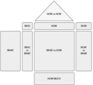
The house of quality is the physical appearance of the QFD method and is also known as the QFD diagram. This is a house-shaped diagram consisting of nine different sections, also called the rooms. [7, pp. 141-150]
Who - The first step in the process to complete the QFD is to identify the customers. The
cus-tomers are often the consumers but it is important to remember that some products are not consumer products. To make sure all customers are included and have been identified, one method to use is to visualize the product’s entire life cycle. Starting with the original problem and where the idea was created, then ending with dismantling and recycling. Analyzing every step of the way and acknowledge the different stakeholders. [7, p. 151]
What - Next step is to identify what the customers want the product to do. To whom the “what”
is important to should also be identified - who vs what. Considered there are stakeholders such as; consumers, production customers and marketing customers, the “what” must include them all. Usually, the consumers want a product that works well, looks attractive, has a long lifetime, is easy to maintain and has many features. While the production customer is more interested in how easy the product is to manufacture, if it can be produced by existing facilities and whether or not it uses standard parts and methods. Finally, the marketing customers wants the product to be easy to store, package and transport as well as being attractive and suitable for display. [7, pp. 151-156]
Who vs What - The who vs what room is dedicated to state the importance and weight of the
requirements. One way to do this is to instruct the customers to rate the requirements from one to ten. Letting one be the least important and ten the most. This however, often gives an insuf-ficient result because it is normal that all the requirements score a high value such as eight, nine or ten. This is because most of the requirements often are considered to be important. A solu-tion to this is to let the customers rate the requirements with a total sum of 100. Giving the most important requirement the highest score and so on. [7, pp. 157-158]
Now & Now vs What - Answering the “now” is done by studying existing products.
Aware-ness of what already is available on the market is essential in developing a successful product. This process can be direct compared to a competition benchmarking [3.3.1] and will reveal the opportunities there are to enhance and improve the existing products. [7, pp. 158-160]
How - To measure how well the customers’ requirements are met, engineering specifications
need to be developed. These originate from the requirements but are stated in terms of param-eters that can be measured. Having a specification saying that the car door should be able to close easily, is not enough since easily can be interpreted differently among users. In this case, easily has to be translated to a targeted value such as e.g. “The closing force of the car door should not exceed 20N”. [7, pp. 160-165]
What vs How - The strength of the relationship between the engineering specification and
customer’s requirement are measured in the “What vs How” room. The ratings are 0 = no lationship, 1 = weak relationship, 3 = medium relationship or 9 = high relationship. Every re-quirement should have at least one strong relationship with a specification. Ideally one specifi-cation should have a relationship with more than just one requirement. [7, p. 166]
How much - In the example of the closing car door, 20N is the targeted force. In this section,
all the targets are set and presented as well as their importance to be met. This leads to evalua-tion how much effort it will expend to reach a target. [7, pp. 166-169]
How vs How - This section exists to easier realize if and how there are dependencies between
the different engineering specifications. When trying to meet one specification, others might get affected in either a positive or negative way. The specifications are shown in a diagram with diagonal lines connecting them together. If, during the progress, one specification is noted to depend or affect another it is shown by rating a “+” if the dependence has a positive effect. The same way a negative effect is shown with a “-”. “++” or “--” can be used to show strong depend-encies. The ideal result to achieve is independence among all specifications. If too many speci-fications depend on another, they should be revisited. [7, pp. 169-171]
3.5 Concept elimination
3.5.1
PUGH
A decision-matrix called Pugh’s matrix can be used when comparing different concepts. The method was invented by Professor Stuart Pugh of the United Kingdom. He saw an opportunity to elaborate the second room in the house of quality, from the QFD [Figure 4]. From there the Pugh’s method was invented [11, p. 61]. The method offers the user the ability to compare dif-ferent concepts to each other and evaluate their ability to meet the determined criteria. The scores can be summarized and provide a result that points out the strongest alternatives. The matrix can have different layouts depending on what is compared, who is doing the com-parison and what you want the process to answer. A general matrix can be divided into five sections and completed in five steps.
Figure 5 shows how a PUGH-matrix could be structured
Alternatives - In this section the different concepts or alternatives are stated. It is important that the concepts have gone through the same amount of work and are at the same progress level. Sketches of the different concepts can be a good way to quickly remember and compare them relative to each other. There is always one concept used as a datum. This can either be an already existing product, abstracted to the same level as the other concepts, or an earlier con-cept estimated to be the strongest alternative. The datum is usually positioned in the first col-umn of the section.
Criteria - To ensure that the product meets the customer’s requirements, engineering specifi-cations are created. These should be able to be answered objectively and are often taken from the requirement specification. Consumer price, general packing, cost or feasibility are some ex-amples.
Importance - To make sure that the result take into account, the different importance of the criteria have to be weighted. This is usually done in the quality function deployment (QFD) [3.3.3] where the relative importance of the requirements are determined. The importance is given as a multiplication factor.
Evaluation - When completing the evaluation, the datum is used to compare all the concepts against the criteria. Each comparison is judged to be better, worse or same as the datum. The results get presented by writing “+1” as better than, “-1” as worse than or “S” as same as. A concept that scores better than the datum on the first criteria will get credited +1. If the criterion has an importance of 5 the result for that concept will be 5, (5 × 1). If the same concept gets evaluated lower than the datum on the second criteria, that has an importance of 3, the result is 2, (5 × 1 + (3 × −1)). This is done with all the concepts and criteria until a final score can be summarized.
Results - If a concept gets a score higher than zero this concept will, in general, meet the re-quirements on a higher level of accuracy than the datum. Which as a conclusion means that this solution is a better alternative. If more than one concept gets a positive result it can be necessary to do further comparisons, making the decision taking possible. [7, pp. 240-243, 157]
3.6 Validity and Reliability
To guarantee quality in any research, it is of importance to evaluate the validity and reliability. High validity ensures a quality research. This proves that the right phenomenon have been studied during the design process. The validity can be strengthen with known and accepted theories, good measuring equipment and accurate measurements. To perform a quality study with good reliability, is rather about discovering the uniqueness that occurs with different situ-ations and the relation to the background, than achieving a correct result. [12, pp. 105-106] Olesen provides five factors in his article “Concurrent development in manufacturing based on dispositional mechanisms” [13] that can be of use in order to describe validity and reliability in a quality research:
• Internal logic – known and accepted theories are the basis of the research, and the work is stringent from the problem to the result.
• Truth – the theoretical and practical result can be used to explain real phenomena. • Acceptance – the research is accepted by the research community. The tools
intro-duced are accepted by practitioners.
• Applicability – the use of the introduced tools leads to enhancements over the situa-tion if they had not been used.
• Novelty value - new solutions are presented or new ways of looking at a problem are introduced.
4
Implementation and Result
This chapter will present what the study resulted in and what implementation that lead into those results.
This concept study began with a pilot study. Here, the intention was to define the demands from a both technical and user perspective point of view. A benchmarking, research gathering, user study and an interview were conducted in order to achieve conclusions from the pilot study. The gathered information was transformed into a product specification to state the demands of the product. Followed by a brain writing process which generated different concepts. The con-cepts later got evaluated and eliminated thereafter. The finalization of the selected concon-cepts got developed in an iterative process.
During the development of the final concepts, the process described in the theoretical back-ground with its associated methods are performed continuously [Produktutveckling - Effektiva metoder för konstruktion och design].
4.1 Pilot study
To be able to gather information and knowledge about both bicycles and carriers, a pilot study had to be performed. This study consisted mostly of information research done on the internet. Getting familiar with all the terms and learning more about racing bicycles in general as well as gather information regarding design differences.
4.1.1
Project planning
In the early stages of this thesis, the project was planned and organized in a Gantt schedule. This to gain understanding of the scope and time needed in every moment of the project. The schedule can be viewed in the attachment chapter [Attachment 1, GANTT].
4.1.2
Benchmarking
The completion of the benchmarking began with the creation of the benchmarking diagram, found in the attachment chapter [Attachment 2, Benchmarking]. This consisted of nineteen fea-tures, design solutions or limitations that were to be compared between eleven different roof mount bike carriers that had been appointed to be the most similar to the Thule Sprint XT. The answers was found by, via the manufacturer's webpage, reading about the carriers and the in-formation that was provided about them.
4.1.3
User study & Interview
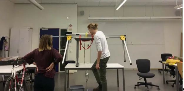
To be able to collect information regarding how the interaction with the existing Thule Sprint XT looked like, a user study was conducted. To be able to replicate as realistic a scenario as possible, without the access to a car, the carrier was mounted to a circular saw rig. The rig had a similar t-track [Attachment 3, Picture of Thule t-track system] as Thule’s car racks have. This made possible for a stable set up. The rig then was secured to a height adjustable table that made it possible to easily change the height to mimic different car heights.
The users executed the mounting of the bike with no other external assistance. This was to en-sure that their interpretations and behavior was not affected by others and therefore making sure for an intuitive experience. The environment was made to be as neutral as possible. The problem the user was told to solve was to mount the bike to the carrier in a way they thought was the correct way and so that they felt comfortable with how it was being secured. The user got no further explanation or manual of how to use the carrier. This was to examine how well the understanding of the product was mediated to the user. In this way, possible improvement opportunities of the product’s intuitive use could easily be noticed. If, however, the user did not know how to interact with the carrier and could not figure out how to mount the bike, help was given.
The experiment was video recorded with the help of a smartphone camera which was mounted to a stand for a stable and consistent shot. The footage then got analyzed and an edited video was created. In total six people got studied and since one did not want to get recorded, video footage of five users was collected.
Figure 6 shows a picture from the user study
Figure 7 shows a picture from the user study
After analyzing the video footage several recurrent problems were noticed. The most obvious one regarded the knob in the front of the carrier, whose function is to tighten the sprints [Figure 32 shows the parts of the scissor system] and thereby securing the bike. It was by many users only assumed as a cover with no intended purpose. If it were to be turned, none of the users com-pleted the tightening fully by turning until the feedback click sounded. The click comes from the internal torque limiter which disengages the mechanism making it impossible to further tighten the sprints. As this being one of the key features that Thule Sprint XT offers and makes it stand out among its competitors, this result strongly suggest that improvements should be done. Furthermore, the general understanding of the carrier and how to use it has in this user study shown to be difficult for first time users without instructions. This suggests that the
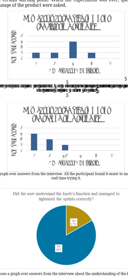
prod-Once a user was introduced to the experiment, they were asked a few questions regarding their previous knowledge of race bikes and their physical appearance, education and gender. This could later be helpful when studying the results since certain exceptional cases of results could be related to a certain starting point. When the experiment was over, questions about the mounting and usage of the product were asked.
Figure 8 shows a graph over answers from the interview. The majority found that the difficulty level of the mounting of bike onto bike carrier was from medium too easy.
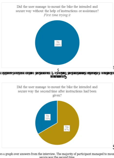
Figure 9 shows a graph over answers from the interview. All the participant found it easier to mount the bike the sec-ond time trying it.
Figure 10 shows a graph over answers from the interview about the understanding of the knob's function 0 1 2 3 4 5 4 3 2 1 N umb er o f u ser s
5 = Very easy, 1 = Difficult
How easy was the bike to mount
the first time trying it?
0 1 2 3 4 5 4 3,5 3 2 1 N umb er o f u ser s
5 = Very easy, 1 = Difficult
How easy was the bike to mount
the second time trying it?
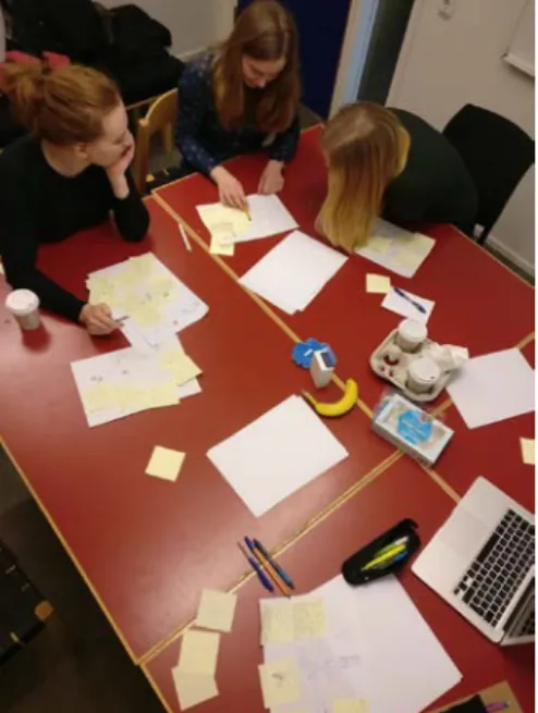
Figure 11 shows a graph over answers from the interview. No one from the user study was able to mount the bike without any instructions.
Figure 12 shows a graph over answers from the interview. The majority of participant managed to mount the bike in a secure way the second time.
4.1.4
Quality function deployment (QFD)
The part of the quality function deployment that were of interest for the development of the new Thule Sprint XT was the weighting factor points which later were used in the PUGH’s matrix. The weighting factor points were established by completing the Technical product study matrix [Attachment 7, QFD] produced by Thule. This matrix is equivalent to the “Who vs What” section of the QFD [3.3.3]. However the method used here differs from how David G. Ullman explains the process. The method Thule has developed to produce the weight factors is by com-paring the requirements against each other. By composing a matrix where the requirements are stated in both the rows and columns, a diagonal comparison where they one by one gets weighed against each other can be done. The input answers only to which of the two, at the time com-pared, have a higher importance than the other and scores 1 respectively 0. If two requirements are rated the same importance they both score 0,5. The result will give all the requirements a weighting factor between zero and the number of requirements used, which in this case were 20. The highest factor reached were 18,5 and the two requirements achieving this were “equally distributed force over the sprints” and “withstand rough handling”. Several requirements had a factor of 17 or higher and the similarity between these were that they contained demands that were set to be reached and not wished to be fulfilled, such as “fit bikes with disk brakes” and “ability to handle carbon fiber frames”.
4.2 Requirement specification
The information from the pilot study together with the requirements resulted in a specification and can be found in the attachment chapter [Attachment 6, Requirement specification]. Since the project was assigned by Thule, some demands were already set by them. Some of the demands, set in the pilot study, were later excluded since they were judged to no longer be relevant to this thesis. They were however, rather important when stages further on in the process were reached. These were demands such as accomplishing the “city car crash test”.
4.3 Concept generation
4.3.1
Session 1
The first concept generation session was conducted in the early stages of the developing process to gather as much external input as possible. The group were handpicked out of students of the technical university of Jönköping, to make sure for a meeting where desired experience and knowledge were present.
When all participants were gathered, the information were introduced to them and a warm up exercise handed out. This was an exercise to activate the creativity and imagination and lasted five minutes. When the five minutes had passed everyone explained what they had drawn to let the others be inspired by their possible different approach.
The focus of this session was to bring out concepts regarding the mounting of the front fork to the carrier. The previous solution, which Thule Sprint XT consist of, features a construction were two sprints are tightened to clamp the drop out areas [Attachment 11, front fork] fastened. The goal was to find new solutions solving the same problem. The participants got instructions to set aside economical and manufacturing limitations. This could increase the imagination and flow of generating solutions.
After this, plain white papers and a few post it notes were handed out. The white paper were used by the participants to sketch and/or write their concept/s. After the four minutes had passed, which this part were set to take, the papers were passed to the person next to. The goal now was, with help of the post it notes, to add on ideas to the original concept. This part was also set to last for four minutes. This was repeated until the original concept, now with at least six additional ideas, ended up at where it originated from. The final step of this concept gener-ation session was to have a common brainstorming where all concepts were freely spoken about and inputs from all participants were welcome.
4.3.2
Session 2
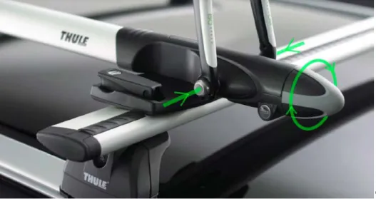
The second concept generation session was decided to have a different orientation than the first one. In focus was to find a solution on how the mechanism of the tightening feature could be constructed. With this being a rather difficult goal to achieve, it was necessary to have clearly specified limitations to the problem. The participants who got invited were informed in advance about the session’s goal and what the limitations were. In this way more solutions and concepts could be produced since the problem was narrowed down to one specific thing and therefore not being too big to grasp. The participants were told to try and come up with a solution to how the tightening mechanism could be designed, still using the same design for the sprints and with an input force [Input] of any kind. This meant that the rotation knob could be changed out for e.g. a lever, a skewer or a button. Which in turn could lead to a linear force instead of a rotating one. To give the participants further knowledge they were sent a video of how a bicycle is fastened to the current Thule Sprint XT as well as a picture [Figure 14] explaining the feature. During the session the method and technique used were the same as in the earlier concept gen-eration session [4.3.1].
4.4 Concept
4.4.1
Concept 1
This concept uses the flexibility of the wire. The axial force needed to tighten the sprints acting in one direction can with the help of wire easily be redirected. This makes for a solution enabling the possibility to eliminate a rotational input and instead have a linear one. One of such could be some sort of lever or arm that with the use of a folding motion pulls the wires resulting in the sprints being tightened. The part in which the wires are fastened to can rotate around its central point which allows for deviations in the fork bones and thereby not risk damaging it.
Figure 15 shows concept 1
4.4.2
Concept 2
This concept uses a specific component to solve the mechanical problem. In this solution, in contrast to the other concepts, the system has its natural state in the tightened position. When the input force is added, the system will open and enabling the mounting of the bike. The input force will separate the sprints. Since the construction continuously aims at attaining the normal state, the tension will maintain and thereby fix the fork. Due to conceivable deviations of the fork bones it is vital to equally distribute the force between the sprints. This is solved by the characteristic of the component.
4.4.3
Concept 3
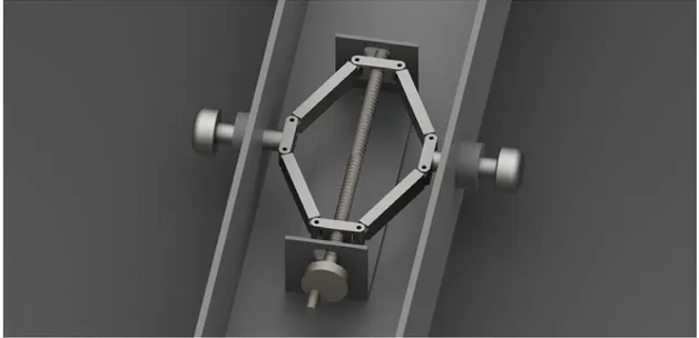
The principle behind this concept is conversion from rotational force to axial force. Since the axle is threaded in both directions with the center as changing point, rotation of it will result in distance change between the both threaded links. Much like the well-known jack screw that is used to lift cars. If the distance increases, the system is tightening, pulling the sprints in. By letting the axle have room to slightly move, the force is able to compensate for deviations of the fork bones and be equally distributed on both sides.
Figure 17 shows concept 3
4.4.4
Concept 4
The principle behind this concept is to redirect the motion from the input force with the use of rails. This is done by letting the sprints be attached to the rail. When the input force moves the rail forwards, the sprints will be tightened. The angle of the rail is determined by the length of the springs. These will, during tightening, get pressed together which will enable the adjustment of the tightening force. This concept uses rigid springs to allow the rail to slightly move and thus compensate for derivations of the fork.
4.4.5
Concept 5
This concept uses a combination of wire and lever to transfer the input force into the direction of the sprints. The input force is applied via a wire. The wire connects with a lever that has an axle to create a pivot point that will transfer the input force into the tightening force of the sprints. The part in which the wires are fastened to can rotate around its central point which allows for deviations in the fork bones and thereby not risk damaging it.
Figure 19 shows concept 5
4.5 Concept elimination
4.5.1
PUGH
The concept elimination process, were the five generated concepts got narrowed down to only two, was performed with help from a PUGH matrix [Attachment 9, PUGH]. The matrix used was produced by Thule, and is customized to fit their developing process and products.
The engineering specifications, listed in the “criteria section” [3.6.1], were taken from the re-quirement specification [Attachment 6, Rere-quirement specification]. The concepts got compared to the datum answering to these specifications one at a time. The datum used was the Thule Sprint XT carrier. The comparison worked out by giving score to the five concepts in regards to their solution and if the demand was improved, worse or the same as the datum.
The result ended in advantage for concept 3 with a score of 101. Since an outcome of a PUGH matrix should be considered as guide lines, the two concepts with highest score were selected. Therefor concept 2 also were considered to be included in the further development, since it scored 100.
4.6 Configuration and Detail Design
4.6.1
Testing of the tightening force
To be able to get determine the tightening force needed for a secure mounting of the bike, tests were conducted. The test equipment consisted of a measuring cell and the quick release skewer of a front wheel. The measuring cell is an instrument used to collect data regarding pressure. When connected to a display, wanted unit and scale can be selected. The output were in these tests given in Newton and measuring the tightening force. The tests were performed by letting people tighten the quick release the same amount they would tighten a wheel to the front fork of a bike. They were asked to stop when they thought they had reached a secure level. The results showed a wide range from between 600 – 6500 N. This test also gave perception regarding what dimension a potential lever would need to enable enough force to be applied.
These tests, together with the observations received from the pulling test [Attachment 10, slippage test], resulted in the determination of the tightening force interval. This was set as a requirement letting the interval reach from 600N-3600N. A tightening force of 600N was the lowest limit of which the bike was fasten securely. The upper limit of 3600N was set as the maximum force a carbon fiber frame could handle without breakage.
Table 1 shows the magnitude of force every participant applied into the system.
Table 2 shows the maximum, minimum and mean value of the force applied into the system.
Figure 20 shows a picture of the test equipment
4.6.2
Testing prototype
The principle behind concept 2 was dependent of a special component’s characteristics. This concept and the construction of its mechanism with the special component needed to be tested to verify its feasibility. The testing also had the intention to reveal if the component would be able to fit inside the construction of a bike carrier or not.
This test required special equipment to be able to give accurate results. These were created in Thule’s prototype workshop with some help of prototype technicians. The created equipment included one metal axle that represent the front wheel quick release. This part had to go through development and two more versions of it were later produced. Washers that would distributed the input force equally on the measuring cell to achieve accurate results also had to be included in the set up. Special washer with engraved ribs [4.6.4], got machined to represent the sprints and faced the drop out area of the fork.
To be able to measure the amount of force applied during the test, a measuring cell was used once again.
Participant:
1
2
3
4
5
6
7
Force (N):
3800
1300
4400
2700
4980
748
6507
Maximum:
6507 N
Minimum:
748 N
Mean
value:
3490,7 N
Figure 21 shows pictures of the first created test equipment. Version 1
Figure 22 shows pictures of the second created test equipment. The axle had to be imporved to ensure an accurate result. Version 2
Figure 23 shows pictures of the final created test equipment. This meant a better dimensioned axle, washers with engraved grooves and special made spacers. Version 3
Figure 24 shows a picture of the test, which engineers from Thule checked.
The results from the tests gave a realization that it was possible to develop concept 2 and still meet the demands from the specification. Necessary knowledge about the needed component were gained and since the results were positive, Thule decided to start a patent process research.
4.6.3
Input
The work the user put into the system for opening and closing of the carrier is called the input force. As the concept generation process began, the limitation to how this input force would take form was unrestricted. The former rotating knob did not need to be recurrent in the new concept. Solutions such as a hand lever, an electrical motorized system or hydraulic were imag-ined to broaden the mindset. However, the solution of how the user could input the force into the system depended on what mechanism was used. This meant that the design solution for the input force had to be done after the mechanism was decided. After having the scissor jack con-cept scoring the highest value from the Pugh’s matrix it was clear that a rotational input was needed. A few of the input force concepts were eliminated straight away with the reason of being too costly. Such as the electrical motorized ones as well as the hydraulic based ones. Having a hand lever produce a rotation torque is possible by the use of gears and interconnecting parts. The simplicity and cost efficiency of a knob were in this context however evaluated much higher.
4.6.4
Sprints
The concepts generated during the first concept generation session were all put aside. This was due to them all consisted of design solutions were the sprints had been removed. They had in-stead other solutions for how the fork could attach. Since the sprints are similar to the way the quick release of the bike wheel fastens, they are considered to be the overall best solution. In this way, the tightening pressure acts on the same areas of the drop outs as the quick release, which is what the bike is built to withstand and therefore most suitable.
Figure 26 shows the drop out of the front fork, with arrows resembling the slippage direction
The design of the sprints are limited since the area on where it will come in contact with the fork do not vary much. Tests were conducted regarding how different ribs or design of the sprint’s head could impact how securely the bike attaches to the carrier. During concept testing [Attachment 10, slippage test] slippage were noticed when flat heads and a tightening force lower than 600 newton were used. Four different design concepts of the sprints got developed; hori-zontal, circular, centric and lock-washer to determine what solution offered best grip between the sprints and the fork. With respect to which resources were available, these designs could not be manufactured and the results come from analyses of the design.
Horizontal
Offers best grip when slippage acts in horizontal or vertical direction, determined by the align-ment of the ribs. When aligned horizontally, highest friction will be given when slippage occurs vertically.
Slippage direction:
Circular
Offers best grip when slippage can occur outwards.
Slippage direction:
Figure 28 shows the sprint with circular ribs
Centric
Offers best grip when slippage in rotation in both direction occurs.
Slippage direction:
Figure 29 shows the sprints with centric ribs
Lock-washer
Offers best grip when rotational slippage in one direction occurs. This direction is when the rotation faces the flat sides of the incline.
Slippage direction:
Figure 30 shows the sprints with lock-washer ribs
Sprint design
Due to the design of the drop outs the front fork will be fixed horizontally and slippage will only occur vertically. The best choice for the design of the sprints are therefore the horizontally aligned ribs. Because of the sprints being fastened to link3a and link3b [Figure 32 shows the parts of the scissor system] the rib alignment will stay in a horizontal position making sure for best possible grip.
4.7 Final concepts
After joint discussion with the project participants from Thule Group, concept 2 got selected as the more interesting and promising one. This concept had a solution to the problem not before thought of by Thule. Because of this, they expressed great interest in it. This was also the reason why details regarding this concept cannot be described or shown in this thesis. Thule Group took action in the patent investigation of the solution and therefore this concept was confiden-tial. Concept 3 was also considered interesting and will as well be presented in this chapter. However, further development, testing and concept finalization were from this point and on-wards mainly focused on concept 2. Since this information also was confidential, the following results will include both concept 2 and 3, but concept 2’s results will be censored.
4.7.1
Concept 2
This concept consists of a solution that utilizes that the value of the applied tightening force has an interval. That interval range from 600 to 3600 N [Attachment 7, Requirement specification]. This interval was stated such that with a force of 600 N, the bike’s fork bones will be tightened to the carrier with just enough force for a firm and sufficient grip. Having a limit of 3600 N makes sure that frames of carbon fiber will not get damaged. The interval allows for solutions where a certain predetermined tightening force was not a must. This in turn leads to the possi-bility of eliminating the need of a torque limiter. This was something that concept 2 takes ad-vantages of. The solution offered in concept 2 was simple yet manages to meet all requirements and are at the same time calculated to have a lower production cost than the Thule Sprint XT. By the usage of the special mechanical component, this concept interacts with the user in only two positions. Either the system is open or closed. The operation of tightening the system, ap-plying the force, have been simplified by doing this. This enhances the user interface and makes for improvements regarding the product’s ability to mediate its usage [Intuition]. When the sys-tem is open, the distance the sprints extend are 10 millimeters which lets a fork with 8 millime-ters of fork bone thickness attach to the carrier with ease. To tighten the sprint the user needs to engage with the input giver, which in concept 2 can have the form of either a knob or a lever, both solutions were proposed to Thule. Then by turning the knob or lowering the lever, the system will close and a force between 600 and 3600 N will react via the sprints on the both fork bones, securing the bike to the carrier.
4.7.2
Concept 3
Figure 31 shows a render of concept 3
Concept 3 was originally inspired by the commonly known scissor jack. This is a product used to partially lift a vehicle or other object off the ground by utilizing the mechanical properties of threads and scissor design. The idea of making use of scissor design as part of the mechanical solution was considered by Thule as a good concept.