ISSN 0347-6030
V/]/r a p p o r t
323 A 1989
Visibility distances to
retrore-flectors in opposing situations
between two motor vehicles at
night
Gabriel Helmers and Sven - Olof Lundkvist
an
l/TIra
A
1.989
Visibility distances to
retrore-flectors in apposing situations
between two motor vehicles at
night
Gabriel Helmers and Sven - Olaf Lundkvist
f 00/!
Statens veg- och trafikinstitut (VT/l - 581 01 Lin/(oping
PREFACE
This report is a shortened English version of the original final report in Swedish (VTI rapport 323).
The research work as well as the work on the translation into English were sponsored by The Swedish Transport Research Board. Christina Ruthger had the main responsibility for the translation and editing of the report.
CONTENTS ABSTRACT SUMMARY N II IH I II t h l wwwwwwwww N N N N N N N H 0 3 0 1 4 : . m e b ub -b ub N N H N N H
BACKGROUND AND PROBLEM Safe visibility distance
Visibility in vehicle lighting
Design traffic situation for the evaluation of
retroreflectors and other visibility promoting measures ISSUES
METHOD
Method for the measurement of visibility distances Experimental design
Retroreflectors in the experiment Test design
Headlights Low beam aiming Subjects
Model of the analysis of variance RESULTS
Large retroreflectors Small retroreflectors
Analysis of variance concerning SMALL RETROREFLECTORS with an area of 100 cm2
Analysis of variance concerning SMALL RETROREFLECTORS with areas of 25 and 100 cm2
Analysis of variance concerning SMALL RETROREFLECTORS with areas of 6.25, 25, and 100 dmz
COMMENTS ON THE RESULTS Large retroreflectors Small retroreflectors
Comments on the analysis of variance concerning SMALL RETROREFLECTORS with an area of 100 cm2 Comments on the analysis of variance concerning SMALL RETROREFLECTORS with an area of 25 and 100 cm2 Comments on the analysis of variance concerning SMALL RETROREFLECTORS with an area of 6.25, 25, and 100 cm2
ANSWERS TO THE QUESTIONS DISCUSSION REFERENCES Page II H 19 19 20 21 21 22 23 23 24 25 27 29
Visibility distances to retroreflectors in opposing situations between two motor vehicles at night
by Gabriel Helmers and Sven-Olof Lundkvist
Swedish Road and Traffic Research Institute (VTI)
8-581 01 LINKoPING Sweden
ABSTRACT
Visibility distances to retroreflectors were registered in full-scale simulations of opposing situations between two motor vehicles at night. Independent variables were the CIL value of the retroreflector, its area, and the light intensity from an opposing vehicle.
The relative importance of these independent variables to the visibility distance was determined.
II
Visibility distances to retroreflectors in opposing situations between two motor vehicles at night
by Gabriel Helmers and Sven-Olof Lundkvist
Swedish Road and Traffic Research Institute (VTI) s-581 01 LINKoPING Sweden
SUMMARY
The aim of this work was to produce basic data concerning the visibility distances of retroreflectors in opposing situations between two motor vehicles at night.
The visibility distances of twelve subjects were measured in simulated full-scale opposing situations between two motor vehicles on a straight and level road. The tests were carried out on a runway with no interference from other traffic.
The variations of the visibility distance were studied in relation to the following independent variables.
- The CIL value of the retroreflector, i.e. the ability of the retroreflector to reflect the light (independently of its area) back to the driver.
- The area of the retroreflector.
- The intensity of the light from an opposing vehicle. The following conclusions can be drawn from the results.
- The visibility distance is primarily determined by the CIL value of the retroreflector, followed by the light intensity of the opposing vehicle.
III
The visibility distance is only influenced by the area of the retroreflector when the size of the retroreflector exceeds 100 cm2.
Safe visibility distances at 90 km/h, i.e. visibility dist-ances exceeding 140 m in opposing situations with a vehicle with a low beam aimed too high, will be obtained when the CIL values of retroreflectors reach 1000 mcd/lux and the areas do not exceed 100 cm2 (observation angle 12 ).
The work resulted in the following recommendations:
The retroreflector standards should comprise CIL values for both observation angles of 20 and 12'.
The CIL value of a retroreflector should be at least 1000 mcd/lux at the observation angle of 12 and not below 600 mcd/lux at an angle of 20 .
1 BACKGROUND AND PROBLEM 1.1 Safe visibility distance
The general problem of vehicle lighting in night-time traffic is to facilitate early detection by drivers of pedestrians and obstacles in the roadway [1][2].
The distance necessary for the driver to discover an obstacle is called the visibility distance to the obstacle. In order to be able to bring the vehicle to a standstill before running into the obstacle, the visibility distance has to exceed the length of the stopping distance. The stOpping distance is a natural safety criterion, which should always be fulfilled.
The Nordic Association of Road Engineers (NVF) estimates that a stopping design distance of 140 m.is required at a speed of 90 km/h [3]. By adding the travelled distance for a reasonable brake reaction time (1.5 s) [4] and the normal braking distance on a wet road surface (u=0.50) to a standstill, a mdnimum safe stopping distance of about 100 m is obtained at a speed of 90 hm/h. Accordingly, a visibility distance of 100 m is regarded as absolutely necessary and 140 m.is desired for a design speed of 90 km/h in vehicle lighting in darkness.
1.2 Visibility in vehicle lighting
A considerable part of night-time traffic research has been devoted to the survey of visibility in vehicle lighting. One of the main results of this research is that the criterion of safe visibility distances can be fulfilled when driving on high beam in situations with no oncoming traffic [5]. The criterion is, however, not fulfilled at the design speed of 90 km/h when driv-ing on low beam and in all vehicle meetdriv-ing situations, irrespec-tive of the vehicle being driven with high beam or low beam [5].
Visibility distances to obstacles on the roadway were measured in order to evaluate possible measures aiming at the improvement of driver visibility at low beam. Furnishing obstacles with retroreflectors is the only measure resulting in safe visibility distances to obstacles on the road [2][6]. A still more effect-ive measure would be to furnish the obstacles with proper light
sources .
In Sweden, it is stipulated by law that cyclists must use lamps and retroreflectors. On the other hand, pedestrians are recom-mended a general use of retroreflectors as the best solution to their visibility problem. In order to guarantee sufficient vis-ibility of objects on or by the road the utilisation of retro-reflectors is often the only realistic solution to the visibil-ity problem.
Despite the fact that the utilisation of retroreflectors has been, and still is, the most effective measure beyond comparison to create favourable conditions for safe visibility distances to obstacles, no comprehensive research and evaluation have been found in literature concerning the visibility of retro-reflectors. Such research is necessary to create a knowledge base for standards and regulations regarding retroreflectors, e.g. for pedestrians.
1.3 Design traffic situation for the evaluation of
retro-reflectors and other visibility promoting measures Vehicles driving on low beam constitute a traffic situation where the use of retroreflectors is necessary to create favour-able conditions for safe visibility distances. Retroreflectors are the only way of being discovered at sufficient distances in the faint light falling within the area above the cut-off of the low beams and which is projected against obstacles at a distance of more than approximately 75 m in front of the car. This means that a proper, correctly aimed low beam on a straight, level road should be chosen for the design traffic situation when evaluating retroreflectors.
The best visibility conditions in low beam illumination are free of opposing glare. Glare is introduced in all vehicle meeting situations. The intensity of glare varies considerably, e.g. due to a too highly aimed low beam of the opposing vehicle, the geometry of the road (hill-tops and bends) and the position of the visual object compared to the source of glare.
As glare directly impairs visibility conditions, glare is a variable which should be varied within the whole range of varia-tions that may usually be expected to be found in traffic. This means that glare should be varied from no glare to maximum glare
from an oncoming vehicle operated with low beams.
Retroreflectors should be so effective that they give safe visi-bility distances also in glaring situations and not only in situations with a normal degree of difficulty. This means that the design traffic situation shouldbe a situation with strong glare. In this study too highly aimed opposing low beams are chosen for the design situation.
In an experiment there are, however, strong reasons for varying the glare variable in a few natural steps. This will on the one hand make it possible to associate to previously obtained evalu-ations of retroreflectors and on the other hand provide general knowledge of the influence of glare on the visibility distances to retroreflectors.
2 ISSUES
The general question to be answered can be outlined as follows: - How does the visibility distance to a retroreflector vary as
regards:
I) the CIL value of the retroreflector, 2) the area of the retroreflector, 2) opposing light.
This issue is descriptive and should be extended with issues
fthat are more explanatory:
- To what extent can the variation in measured visibility dist-ances be explained by the variation of the CIL value and area of the retroreflector and by the variation of glare?
3 METHOD
3.1 Method for the measurement of visibility distances Measurements of visibility distances were carried out according to a well-tested method [7], implying a full-scale simulation of a meeting situation on a straight and level road closed to traffic. In this case the runway on an airfield was used.
Three subjects are driven as passengers in a passenger car (Volvo 121). Each subject s task is to discover a black obstacle furnished with retroreflectors, as early as possible, and then indicate the discovery by pressing a noiseless switch held in the hand. The driver s task is to drive the vehicle at a constant speed and lateral position to the shoulder which have been specified for the test (according to Figure 1 below).
By means of a tape recorder in the car, the impulses from the subjects switches are recorded together with the impulses from the fixed positions along the road (runway) for the determina-tion of posidetermina-tion and also impulses via a coupling on the speedo-meter wire as a basis for distance calculation. The measurement error of the measured visibility distances is less than 10.5 m
(concerning recording equipment and calculation program).
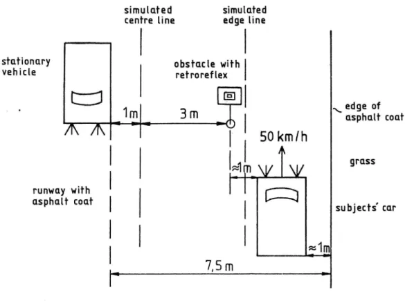
The oncoming car is parked in the middle of an "imaginary" adjacent traffic lane in order to simulate the normal lateral position of the vehicle on a two-lane road. The black obstacle with retroreflectors is positioned on a level with and 4 m by the side of the parked opposing vehicle, i.e. just within an imaginary shoulder on the right-hand side. The vertical distance between the centre of the retroreflector and the road surface is 0.55 m. In order not to take any risks that on any occasion the retroreflector will be illuminated by the light from the asym-metric sector of the low beam headlights on the subjects' car, the obstacle is passed on the left side as if the subjects car were being driven on an imaginary shoulder. The simulated
1*2
2 .4 :3
simulated simulated centre line edge line
Sm c mry obstacle with
VEh'Cle
refrareflex
tj edge of W 1m r. 3 m \ asphalt coa rA\
[ 50kmlh
Ly grassgavTv
runway with C:aSphalf (out I subjecfs'car
_
7,5 m
r
Figure 1 Experimental arrangement of the test
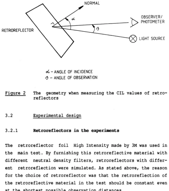
The test situation implies that the lateral position of the subjects car will be of very little importance to the length of the visibility distances. The lateral distance between the opposing car and the retroreflector will, however, be of con-siderable importance to the visibility distance at varying degrees of glare [8]. This distance was 4 m, which corresponds to the distance between an obstacle on the right-hand side of the road which is passed by a vehicle on the opposite traffic lane of a two-lane road. The seating positions of the subjects in the vehicle were not considered to have any influence upon the visibility distance. It is true that both the angles of observation and incidence depend on the distance and position of the observer (see Figure 2 below). At long visibility distances, however, the characteristics of the retroreflector are almost independent of small variations of these angles.
NORMAL
OBSERVER/ ._____ -]:>> PHOTOMETER UGHT SOURCE RETROREFLECTOR oC - ANGLE OF INCIDENCE 0 - ANGLE OF OBSERVATION
Figure 2 The geometry when measuring the CIL values of retro-reflectors
3.2 Experimental design
3.2.1 Retroreflectors in the experiments
The retroreflector foil High Intensity made by 3M was used in the main test. By furnishing this retroreflective material with different neutral density filters, retroreflectors with differ-ent retroreflection were simulated. As stated above, the reason for the choice of retroreflector was that the retroreflection of the retroreflective material in the test should be constant even at the shortest possible observation distances.
Retroreflectors where CIL values and areas were varied according to Table 1 were used in the test.
Table 1 Retroreflectors used in the test are marked (X). CIL values in mcd/lux and areas in cm2.
area 6.25 25 100 400 1600 62.5 X X X CIL 250 X X X X X 1000 X X X X 4000 X X X
The CIL values stated in Table l are approximate and as men-tioned previously, not totally independent of the observation distance. In practice, retroreflectors used in the experiments had CIL values that were about 15 per cent lower than the cal culated CIL values given in Table 1.
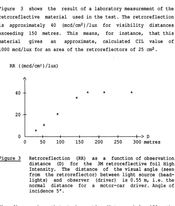
Figure 3 shows the result of a laboratory measurement of the retroreflective material used in the test. The retroreflection is approximately 40 (mcd/cm2)/lux for visibility distances exceeding 150 metres. This means, for instance, that this material gives an approximate, calculated CIL value of
1000 mcd/lux for an area of the retroreflectors of 25 cm2. RR ((mcd/cm2)/lux) A 40 m * * * * 20- * * * O : : : : : : > D 0 50 100 150 200 250 300 metres Figure 3 Retroreflection (RR) as a function of observation
distance (D) for the 3M retroreflective foil High Intensity. The distance of the visual angle (seen from the retroreflector) between light source (head-lights) and observer (driver) is 0.55 m, i.e. the normal distance for a motor-car driver. Angle of incidence 5°.
The figure shows that at observation distances below 150 m the retroreflection is no longer independent of the observation distance. This is due to the variation of the angles of observa-tion and illuminaobserva-tion. At an observaobserva-tion distance of 95 m, for example, retroreflection has been reduced from approximately 40 (mcd/cm?)/lux to approximately 20 (mcd/cm?)/lux. The cal-culated and advisable CIL levels in the main test (i.e. 4,000, 1,000, 250 and 62.5 mcd/lux) are only reached for observation VTI REPORT 323A
distances exceeding approximately 150 metres and for the measurement geometries concerned.
In order to obtain retroreflectors with different retroreflec-tion, but with the same characteristics as the retroreflective material shown in Figure 3, this material was furnished with different neutral density filters.
In summary, the measured CIL values for the retroreflectors used in the experiments were all somewhat lower than the calculated values. The deviation was, however, small for the observation angle of 12 .
3.2.2 Test design
To be able to answer the general issue, formulated in Section 2, a test with the following independent variables was carried out: - The CIL value of the retroreflector,
- the area of the retroreflector, - the glare from the oncoming vehicle.
The CIL value of the retroreflector was varied in four levels (62.5, 250, 1000, and 4000 mcd/lux). The area was varied in five levels (6.25, 25, 100, 400, and 1600 cm2) and the glare from the headlights of the opposing vehicle was varied in three levels (parking lights, correctly aimed low beam (i0°) and highly aimed low beam (+1.5°)). If all these levels or positions of the inde-pendent variables are combined, 4*5*3=60 different test tions will be obtained. The considerable number of test condi-tions is a good reason for dividing the main test into several tests with fewer conditions.
It was our choice to divide the main test into two parts: One test with LARGE RETROREFLECTORS and one test with SMALL
RETRO-10
the corresponding retroreflectors in the second experiment ranged from 6.25 to 100 cm2, as reported in Table 2.
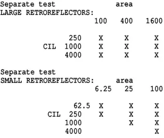
Table 2 Retroreflectors used in the two separate tests (LARGE and SMALL RETROREFLECTORS, respectively) are marked X in the table. It should be noted that for the separ ate test LARGE RETROREFLECTORS, all locations in the table are filled, while three combinations of CIL values and areas are missing in the table of SMALL RETROREFLECTORS.
Separate test area LARGE RETROREFLECTORS: 100 400 1600 250 X X X CIL 1000 X X X 4000 X X X Separate test
SMALL RETROREFLECTORS: area
6.25 25 100 62.5 X X X CIL 250 X X X 1000 X X 4000 X
In the separate test LARGE RETROREFLECTORS all variable levels were combined, which means that an experiment consists of 3*3*3=27 test conditions. In each glare condition (3) the obstacle with the retroreflector was removed on one (1) occasion
(3*1=3). This control condition was entered in order to check that each subject really had discovered the retroreflector before he or she indicated the discovery by pressing the switch. Each replication of the experimental conditions thus comprises 3*3*3+3=30 different runs towards each position of the visual target.
Two positions of visual targets were used on the runway - one for each direction, as can be seen in Figure 4. This means that when the subjects car had passed the first position of the visual target and turned, on the way back the car was driven towards the second position of the visual target on the opposite side of the runway.
11
All 30 conditions were randomly presented at each position of the visual target. For each position of the visual target and each replication the experimental conditions were randomly
drawn. ,.,. _.
/
\
/// stationary / vehk e \t: C?
T
I
A A
l posHion of obstacle 3S
I
A
'U E + j?8
:-'~.'
5 .ox'
IE
3 >2
:1 position of W V J' obstacle C333 w W subjects car[ [12;] 5::
stationary I vehk e /\
\
/
_
\
/
JL
\
\\\__~__ >_ ,///
Figure 4 Positions of visual targets on the runway and the runs made by the subjects car. The distance between the positions of the visual targets along the runway is 600 m.
In the test with LARGE and SMALL RETROREFLECTORS, respectively, all experimental conditions were presented four times to each subject. This means a total of 30*4=120 measurements or 60 runs in Figure 3, for each experimental occasion.
12
Both experiments, LARGE and SMALL RETROREFLECTORS, were carried out during four evenings with three new subjects on each occa-sion. This means that 12 subjects participated in each experi-ment and that there were 48 measurements in each condition (12 subjects * 4 repetitions = 48 measurements).
The experiment with SMALL RETROREFLECTORS is in all applicable parts a repetition of the experiment with LARGE RETROREFLECTORS. It differs from the experiment with LARGE RETROREFLECTORS con-cerning the following points:
The CIL values were varied in four levels and the areas in three. This means 3*4=12 combinations. Three of these combina-tions cannot be carried out due to the fact that the smallest areas do not allow a combination with the highest CIL values. (See Table 2 above.) For this reason 3*4-3=9 retroreflectors remained for use in the experiment. These nine SMALL RETRO-REFLECTORS were then combined with the same glare and control conditions as for LARGE RETROREFLECTORS: 9*3+3=30 conditions. Still another difference between the experiments with LARGE and SMALL RETROREFLECTORS is that the results cannot be analysed by a single analysis of variance, since this requires all combina-tions of variables to be available. This means that the results of LARGE RETROREFLECTORS can be subjected to one (1) analysis of variance comprising all 3*3 combinations, while the consequence of SMALL RETROREFLECTORS will be that three (3) different analyses of variance have to be carried out. Depending on area and CIL value, these analyses will comprise 1*4, 2*3 and 3*2 levels, respectively.
13 3.2.3 Headlights
The headlights used in the test were 7 inches in diameter and were made by Bosch, with the type designation 0 301 600 107, and approved according to ECE Regulation 20. The light pattern of each headlight was checked visually before assembly in order to avoid combinations of headlight and lamp that would give a devi-ating beam pattern.
3.2.4 Low beam aiming
The low beam aimings of the subjects car and the two stationary opposing vehicles (Volvo 121 and Volvo 140) were carried out in a vehicle laboratory towards a purpose-built screen at a dist-ance of 10 m in front of the headlights. The platform where the vehicles were positioned had been balanced and the screen adjusted to deviations from a totally horizontal plane. During the aiming procedure the vehicles were loaded as in the
experi-ment.
3.2.5 subjects
The subjects, aged 20 to 30 years, were mainly students in Linkoping. They were not subjected to any examination of vision prior to the experiment but have on the other hand experienced their vision as "normal". Consequently, the group has not been selected but can be assumed to be typical for people of the same age not experiencing any disability regarding vision.
3.2.6 Mbdel of the analysis of variance
In order to be able to quantify the relative size of the effects on visibility distances to retroreflectors that can be traced
14
analysis of variance of the data. For a more detailed explana-tion to the model of analysis of variance used, we refer to Keppel, section V "Within-Subjects Designs" [9].
In every analysis of variance the effect of CIL value, area of retroreflector, and vehicle meeting beam, as well as interaction effects between these, were tested. All F tests were carried out at the 5% level of significance, which means that a proven effect is true with the probability of 0.95.
The "omega square" (m2) was also calculated for every effect. m2 for e.g. CIL states the proportion of the total variance of measured visibility distances in the test that can be explained by the variation in CIL values. Consequently, this is a measure quantifying the strength of an effect, unlike the F value, which only states whether an effect can be explained by chance or not, with the risk level chosen.
15 4 RESULTS
Mean values of visibility distances for the conditions in the test are reported below. The results of the analyses of variance are briefly presented. (Complete variance tables are published in the Swedish edition of this report: VTI Rapport 323.)
4.1 Large retroreflectors
Visibility distances to the retroreflectors in the separate test LARGE RETROREFLECTORS, i.é. retroreflectors with calculated CIL values of 250, 1000, and 4000 mcd/lux and areas of 100, 400, and 1600 cm2 are shown in Table 3.
Table 3 Visibility distances (m) to LARGE RETROREFLECTORS with calculated CIL values of 250, 1000 and 4000 mcd/lux and areas of 100, 400, and 1600 cm2 in three meeting situations (Group mean values)
VISIBILITY DISTANCE (m) OPPOSING CIL area (cmz)
BEAM (mcd/lux) 100 400 1600 Parking lights 250 198 201 157 1000 291 283 275 4000 388 402 388 Correctly aimed 250 153 157 113 low beam 1000 235 231 205 4000 329 326 306 Highly aimed 250 103 85 39 low beam 1000 173 155 127 4000 252 253 212
The results in Table 3 are illustrated in Figure 5. A confidence interval of 95% is also presented for each average value.
visibiUiy distance
(m)
A
400 H C|L=l+000 mcd/lux H C|L=1000 mcdllux C> -<) C|L= ZSOIncd/lux 300* 200100 M: parking lights M: correctly aimed
low beam I4=I ghw c med . low beam 0 I I I I I I I I [I 100 400 1600 100 400 1600 100 400 1000 areaicmzi Figure 5 Visibility distances (m) to LARGE RETROREFLECTORS in
three vehicle meeting situations, as a function of the calculated CIL values and areas of the retrore-flector. The vertical lines indicate a confidence interval of 95% for each mean value (Group mean values)
The result of the analysis of variance is summarised in Table 4. Table 4 Summary of the results of the analysis of variance
for the separate test LARGE RETROREFLECTORS
Effect Significant w? on the 5% level
CIL (C) yes 0.55 area (A) yes 0.02 opposing beam(OB) yes 0.28 C*A yes 0.00 C*OB yes 0.00 A*OB yes 0.00 C*A*OB no 0.00
17 4.2 Small retroreflectors
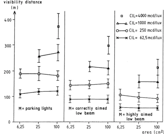
Table 5 reports the visibility distances to retroreflectors in the separate test SMALL RETROREFLECTORS, i.e. retroreflectors having calculated CIL values of 62.5, 250, 1000, and 4000 mcd/lux and areas of 6.25, 25, and 100 cm2. (Group mean values)
Table 5 Visibility distances (m) to SMALL RETROREFLECTORS with calculated CIL values of 62.5, 250, 1000, and 4000 mcd/lux and areas of 6.25, 25, and 100 cm2.
(Group mean values)
VISIBILITY DISTANCE (m) OPPOSING CIL area (cm2)
BEAM (mcd/lux) 6.25 25 100 Parking lights 62.5 110 120 122 250 190 189 182 1000 262 273 4000 375 Correctly aimed 62.5 88 90 90 low beam 250 145 148 152 1000 218 212 4000 300 Highly aimed 62.5 57 54 53 low beam 250 108 98 91 1000 159 159 4000 215
The results in Table 5 are reported graphically in Figure 6 with a confidence interval of 95% for each mean value.
18 visibihfy distance (m) A a CIL=4000 mcd/lux
1 00
H CIL=1000 mcdllux
O O (IL: 250 mcd/lux X x C|L= 62,5mcd/lux 300200 - PH
H
_
100 - W
I
I+
i
M: parking lights M: correctly aimed W low beam M: highly aimed
low beam
0 I I I I I I I I I
6,25 25 100 6,25 25 100 6,25 25 100 nreu(cm2) Figure 6 Visibility distances (m) to SMALL RETROREFLECTORS in three vehicle meeting situations, as a function of the calculated CIL values and areas of the retrore-flector. The vertical lines indicate a confidence interval of 95% for each mean value (Group mean values)
As stated in 3.2.2, the test with SMALL RETROREFLECTORS could not be carried out with all the theoretically possible combina-tions of posicombina-tions in the independent variables. The analysis of variance was thus divided into three parts:
a) SMALL RETROREFLECTORS with an area of 100 cm2 b) SMALL RETROREFLECTORS with areas of 25 and 100 cm2
c) SMALL RETROREFLECTORS with areas of 6.25, 25, and 100 cm2. These analyses of variance are thus reported separately in Sections 4.2.1, 4.2.2, and 4.2.3, respectively.
19
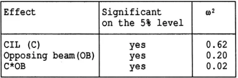
4.2.1 Analysis of variance concerning SMALL RETROREFLECTORS with an area of 100 cm?
As the area was not varied it has only been possible to study the visibility distance as a function of the CIL value of the retroreflector in different vehicle meeting situations. As can be seen from Table 5 the calculated CIL value was varied in four steps: 62.5, 250, 1000, and 4000 mcd/lux.
Table 6 Summary of the analysis of variance for SMALL RETRO-REFLECTORS with an area of 100 cm2
Effect Significant m2 on the 5% level
CIL (C) yes 0.62 Opposing beam(OB) yes 0.20 C*OB yes 0.02
4.2.2 Analysis of variance concerning SMALL RETROREFLECTORS with areas of 25 and 100 cm?
This analysis includes variable values typical for pedestrian retroreflectors, concerning both area and CIL value. The area was varied in two levels: 25 and 100 cm2 and the calculated CIL value in three levels: 62.5, 250 and 1000 mcd/lux.
20
Table 7 Summary of the analysis of variance of SMALL RETRO-REFLECTORS with areas of 25 and 100 cm? and cal-culated CIL values of 62.5, 250, and 1000 mcd/lux.
Effect Significant m2 on the 5% level
CIL (C) yes 0.53 area (A) no 0.00 opposing beam(OB) yes 0.26 C*A no 0.00 C*OB yes 0.01 A*OB no 0.00 C*A*OB no 0.00
4.2.3 Analysis of variance concerning SMALL RETROREFLECTORS with areas of 6.25, 25, and 100 cm?
The purpose of this analysis of variance is above all to study the function of very small retroreflectors (as small as 6.25 cm ). One question could be whether there should be a lower limit for the area of a retroreflector.
Table 8 Summary of the analysis of variance of SMALL RETRO-REFLECTORS with areas of 6.25, 25, and 100 cm? and calculated CIL values of 62.5 and 250 mcd/lux.
Effect Significant m2
on the 5% level
CIL (C) yes 0.33 area (A) no 0.00 opposing beam (OB) yes 0.38 C*A yes 0.00 C*OB yes 0.01 A*OB no 0.00 C*A*OB yes 0.00
21 5 COMMENTS ON THE RESULTS 5.1 LARGE RETROREFLECTORS Table 3 and Figure 5 show that
- to a high degree the viSibility distance is determined by the
CIL value of the retroreflector and the type of opposing beam,
- the visibility distance decreases with increasing area. This is particularly evident in the interval 400-1600 cm2,
- in vehicle meeting situations with an opposing highly aimed low beam, safe visibility distances (i.e. visibility dis-tances exceeding 140 metres) are only obtained for retro-reflectors the calculated CIL values of which exceed or equal 1000 mcd/lux (observation angle 12 ) and the areas of which are less than or equal to 100 cm2.
The main result of the three-way analysis of variance (Table 4) can be summarised as follows:
- All main effects and two-factor interactions are significant. - The variation in CIL value explains 55%
The variation in opposing beam explains 28% The variation in area explains 2%
-of the total variance of the measured visibility distances in the test.
This means that the explanation value of the variation in inde-pendent variables can be denoted 28 : 14 : 1.
Even if all two-factor interactions are significant each of them explains less than 0.5% of the total variance of the material.
22
A two-way analysis of variance for each opposing condition shows - that the "explanation value" of the area increases with increasing glare, from. 1% opposing parking lights, via 3% opposing correctly aimed low beam, to 8% opposing highly aimed low beam.
Finally, the entire "explanation value" of the variation in all independent variables explains 85% of the total variance. This is a very high value which shows, for example, that the test was carried out under good experimental control.
5.2 SMALL RETROREFLECTORS Table 5 and Figure 6 show that
- to a high degree the visibility distance is determined by the CIL value of the retroreflector and the type of meeting beam, - the visibility distance is not influenced by the area of the
retroreflector in the interval 6.25-100 cm?,
- in vehicle meeting situations with opposing highly aimed low beams, safe visibility distances (i.e. visibility distances exceeding 140 metres) are only obtained for retroreflectors
the calculated CiL values of which exceed or equal
1000 mcd/lux (observation angle 12 ).
- in vehicle meeting situations with correctly aimed opposing low beams or parking lights safe visibility distances (i.e. visibility distances exceeding 140 metres) are obtained for retroreflectors the calculated CIL values of which exceed or equal 250 mcd/lux (observation angle 12').
The results of the different analyses of variance will be com-mented on in Sections 5.2.1, 5.2.2, and 5.2.3 below.
23
5.2.1 Comments on the analysis of variance concerning SMALL RETROREFLECTORS with an area of 100 cm?
The main results of the two-way analysis of variance (see Table 6) can be summarised as follows:
- Both the main effects and the interaction are significant. The variation in CIL value explains 62%
The variation in opposing beam explains 20% -of the total variance in the material.
The last-mentioned fact means that the relation in the "explana-tion value" between the two independent variables, CIL value and opposing beam, is 3 : 1. In the test LARGE RETROREFLECTORS the corresponding relation was 2 : 1. This difference can be ex-plained by the fact that the variation of CIL values increased: 62.5 mcd/lux was used as lowest value instead of 250 mcd/lux.
5.2.2 Comments on the analysis of variance concerning SMALL RETROREFLECTORS with areas of 25 and 100 cm?
The main results of the three-way analysis of variance (see Table 7) can be summarised as follows:
- The main effects of CIL value (C) and type of opposing beam (OB) are significant while the effect of area (A) is not significant.
- In this case the variation in CIL value explains 53% and the variation in opposing light 26% of the total variance of the material.
- The interaction C*M is also significant and explains 1% of the total variance.
24
In this case the relation in "explanation value" between the variation in CIL value and opposing light is 2 : 1. This result is a repetition of the result of LARGE RETROREFLECTORS, where the ranges of both CIL values and meeting beams were the same as in this analysis.
5.2.3 Comments on the analysis of variance concerning SMALL RETROREFLECTORS with areas of 6.25, 25, and 100 cm? The main result of the three-way analysis of variance (see Table 8) can be summarised as follows:
- The main effects of CIL value (C) and type of opposing beam (OB) are significant while the effect of area (A) is not significant.
- In this case the variation in CIL value explains 33% and the variation in opposing light 38% of the total variance of the material.
- The interaction C*OB is also significant and explains 1% of the total variance.
In this case the relation in "explanation value" between the variation in CIL value and opposing light is approx. 1 : 1. The "explanation value" of the CIL value is lower than in previous analyses. This result is in line with the fact that the varia-tion in CIL value was lower in this separate analysis. The calculated CIL value was varied in only two steps, i.e. 62.5 and 250 mcd/lux.
25 6 ANSWERS TO THE QUESTIONS
The answers to the questions in Section 2 can be summarised as follows:
1) The visibility distance to a retroreflector depends to a high degree on the CIL value of the retroreflector. The higher the CIL value, the longer the visibility distance.
2) The visibility distance to a retroreflector depends to a high degree on the strength of the glaring light. The stronger the glaring light, the shorter the visibility distance.
3) Concerning retroreflectors with identical CIL values, the visibility distance is independent of the area of the retro-reflector, if not exceeding 100 cm2. Larger areas give shorter visibility distances.
In order to be able to answer the specific question concerning the importance of the independent variables (CIL value, area and type of light from the opposing vehicle) to the visibility dist-ance to a retroreflector, the results have to be related to the range of these variables in the different tests and analyses: The calculated CIL value was varied in a total of four levels: 62.5, 250, 1000, and 4000 mcd/lux.
The area was varied in a total of 5 levels. The three largest were used in the separate test LARGE RETROREFLECTORS, i.e. 100, 400, and 1600 cm2 and the three smallest in the separate test SMALL RETROREFLECTORS, i.e. 6.25, 25, and 100 cm2.
The relationship between the levels of both CIL values and areas is identical in the way that every higher/larger level is four times higher/larger than the previous level. The relationship between the levels in both variables can thus be described by
26
The type of opposing light was varied in order to cover a rea-listic interval of glare in night-time traffic. The parking light is then a "zero-level" as regards glare, and simultane-ously it makes the subjects in the experiment aware of the position of the opposing stationary car. A correctly aimed meet-ing low beam is the normal condition which makes it possible to compare the results obtained in this test with the results from previous studies [6][10]. The highly aimed opposing low beam must constitute a high but realistic and frequent level of glare on the road, which thus should be dimensioning for the demands
on retroreflectors.
In these circumstances the importance of the CIL value and the area of the retroreflector can be quantified (by means of omega square m2) and related to the variation of type of opposing beam to which a driver can be expected to be exposed when detecting obstacles such as a pedestrian wearing retroreflectors in night-time traffic.
When the levels of both CIL value and area vary in the relation 1 : 16, the variation in CIL value is approximately 25 times as important as the corresponding variation in the area of LARGE RETROREFLECTORS, i.e. retroreflectors the area of which varies from 100 to 1600 cm2.
The variation in CIL value for both LARGE and SMALL RETRORE-FLECTORS is twice as important as the variation in type of opposing light.
The areas of SMALL RETROREFLECTORS, i.e. retroreflectors the areas of which vary from 6.25 to 100 cm2, are not important. The visibility distance to LARGE RETROREFLECTORS decreases some-what as a function of increasing area. This effect is most obvious at strong glare, i.e. the condition highly aimed oppos-ing low beam.
27
In order to compensate for the effect of area, which is shown in Figure 4, the CIL value of retroreflectors with areas exceeding 100 cm2 has to be adjusted upwards.
7 DISCUSSION
An important problem in all research is to try to give an answer as to what extent the obtained results can be generalised for other situations and other people.
As our subjects were a non-selected group of students and their task was of a perceptual and not intellectual nature, it is reasonable to assume the following: The relative differences in the length of the visibility distance between the different experimental conditions can be assumed to be valid for young people with no experienced visual disability (with or without glasses).
As the eye's sensitivity to glare increases with age it is also reasonable to assume that the reported relative importance between glare on the one hand and the CIL value and area of the retroreflector on the other hand changes with increasing age by an increase in the relative importance of glare. The amount of such an expected increase cannot be stated without further studies.
In Section 1.1 the visibility distance 100 m has been regarded as absolutely necessary and that of 140 m as desirable at a design speed of 90 km/h. As the visibility distances in this report were measured in a number of constant conditions with favourable variable values we recommend the visibility distance of 140 m as a criterion when formulating the functional demands for devices such as pedestrian retroreflectors.
28
The ability of the retroreflector to reflect light from the headlights back towards the driver depends to a very high extent on the angle of observation and thus the distance between the driver and the retroreflector.
The smaller the angle of observation the larger the CIL value. This has a tendency to be valid generally for all retroreflec-tors down to an angle of observation of approx. 12 , which to the normal passenger car driver corresponds to a distance to the retroreflector of approximately 150 m. As an angle of observa-tion of 12' and an observation distance of 150 m is almost identical to the criterion chosen for the safe visibility dis-tance, i.e. 140 m, it is suitable to specify the minimum value of CIL at an angle of observation of 12 . This angle also corresponds to the American standard for measurement of retro-reflectors.
As appears from the above-mentioned, it is possible to expect visibility distances shorter than 140 m in unfavourable situa-tions. Simultaneously, we have argued for a safe visibility distance not shorter than 100 m at 90 km/h. By also specifying the minimum value of CIL at an angle of observation of 20 , which corresponds to an observation distance for a driver of approximately 95 m, the demands on retroreflectors should natur-ally be connected to the interesting interval of safe visibility distance. The angle of observation of 20 is a European standard in the measurement of retroreflectors.
According to the above-mentioned, requirements on retroreflec-tors should be based on the angles of observation of both 12 and 20 .
29 REFERENCES
[1] Perel, M., Olson, P.L., Sivak, M. & Medlin, J.W.: Motor Vehicle Forward Lighting. SAE Technical Paper Series
[2]
[3]
[4]
[5]
[6]
[7]
[8]
[9]
[10]
830567, 1983.Helmers, G.: Upptackt av hinder och visuell ledning i for-donsbelysning. Lampetten, Vol. 16, nr 2, 1981, eller VTI-Sartryck, no. 66, 1982.
Nordiska Végtekniska Forbundet (NVF): Fardtekniska Grund-varden. Rapport nr 5, 1976.
Brake Reaction Times. Johansson, G. & Rumar, K.: Drivers
Human Factors, 13 (1), 1971. Helmers, G.
Visibility. 1, 1975.
& Rumar, K.: High Beam Intensity andObstacle Lighting Research and Technology, Vol. 7, No. Berggrund, U. & Rumar, K.: Fotgangarreflexer - egenskaper och synbarhet. Opublicerad statusrapport, Psykologiska institutionen, Uppsala univ, 1975.
Johansson, G. & Rumar, K.: Visible Distances and Safe Approach Speeds for Night Driving. Ergonomics, Vol. 11, No. 3, 1968.
V03, J.J.: Disability Glare - A state of the art report. CIE-Journal, Vol. 3, no. 2, 1984.
Keppel, G.: Design & Analysis. A Researcher s Handbook. Second edition, Prentice Hall, 1982.
Rumar, K.: Pedestrian Safety In Night Driving. Interna-tional Conference on Pedestrian Safety, Technion City, Haifa, Israel, 1976.