Research
2010:24
On Cost Estimate for
The present study has been financed by a research grant from the Swedish
Radiation Safety Authority, SSM.
The conclusions and views presented are those of the author/s and do
not necessarily coincide with those of the SSM. It ought to be stressed
that a research activity is independent of the regulatory oversight
re-sponsibilities of SSM.
SSM perspective
BackgroundThe present generation has the responsibility to ensure and guarantee
that sufficient financial resources are accrued into the Swedish Nuclear
Waste Fund to cover all future costs. Thus, the next generation, as well as
any succeeding generations, will have the financial resources required
in order to undertake the necessary measures, in an appropriate
man-ner, for the decommissioning and dismantling of the nuclear facilities
and for the construction and operation of long-term storages for the
radioactive waste generated. These measures must be congruent and
compliant with the environmental and health codex in Sweden.
The ability of the Society to take care of the future environmental
liabi-lities will support a sustainable and long term credibility of the Swedish
financing system for nuclear waste liabilities.
SSM conducts systematic examinations and reviews of the estimates
submitted by the Swedish nuclear industry in order to ensure the
ade-quacy and accuracy of the costs estimations for each of those individual
nuclear facilities, which will become candidates for decommissioning
and dismantling within a foreseeable future.
Purpose of the project
The main scope of this study has been to calculate the future cost for
decommission and dismantling the Isotope central at the Studsvik site
using the OMEGA CODE.
Detailed empirical information is used in the study for “bench-marking”
purposes, in such cases when there is a need to supplement and correct
field data from the industry. In the present study, data has been
retrie-ved and organized such that the estimated costs for decommissioning
of the Isotope Central become transparent and reliable. This approach
gives a preliminary qualitative indication about the accuracy of the cost
estimate delivered by the industry.
dismantling (including contingencies) of the Isotope Central
falls within the range of 29,3 to 30,3 M€.
2) Estimated number of man-power hours needed are in the range
196 000 to 203000.
3) Some costs associated with declassification activities warrant
further analysis if a further sharpening of the accuracy is required.
4) The present methodology for estimation of future nuclear waste
liabilities is a good example of how transparent cost estimates
can be modeled, presented and scrutinized.
5) The way to handle the uncertainty and risk is always a trade-off
between the accuracy of the measurement of the level of
conta-mination vis-a-vis more extensive levels of radiological mapping
at an individual facility.
Continued work
There is always a need for future studies to develop better estimates. In
the short term, our understating and communication can be improved if
similar studies are undertaken that reproduce the present study.
Likewise, more effort is needed in order to enhance the didactic
dimen-sion of the result, so that the dialogue with different stakeholder groups
can be more focused and efficient.
Effects on SSM work
SSM will use the current study as support in the review of the year 2010
of the future decommissioning costs for the older nuclear facilities that
fall under the Studsvik Act. (The Isotope Central is per se not a nuclear
facility, but the cost for decontamination and dismantling of this facility
is included in the Studsvik Act).
Project information
Staffan Lindskog has supervised and co-ordinated the project on behalf
of SSM. Similarly, Marek Vasko has co-ordinated the project on behalf of
DECOM. He has leaded the project group with determination and skill.
SSM reference: SSM 2009/2104
CONTENTS
ABBREVIATIONS ... 4
REFERENCES ... 5
1. INTRODUCTION ... 9
2. WORLDWIDE D&D APPROACH TO RESEARCH LABORATORIES AND HOT CELLS ... 11
2.1. COMMON FEATURES OF RESEARCH LABORATORIES TO BE DECOMMISSIONED ... 11
2.2. DECOMMISSIONING STRATEGY FOR RESEARCH FACILITIES AND HOT CELLS ... 11
2.3. EXAMPLES OF NATIONAL EXPERIENCE ... 13
2.3.1. Decommissioning of nuclear laboratories at SCK•CEN, Belgium ... 13
2.3.2. Decommissioning of nuclear medicine department and radioisotope workplace in the Czech Republic ... 14
2.3.3. Lessons learned in decommissioning laboratory facilities, UK ... 16
2.3.4. The US approach to reduce environmental risk associated with laboratory decommissioning ... 17
2.3.5. On-site experience from laboratory plant D&D in Studsvik ... 19
3. BRIEF SURVEY OF ISOTOPE CENTRAL BUILDING... 21
4. DESCRIPTION OF DECOMMISSIONING COST CALCULATION CODE OMEGA ... 27
5. CONDITIONS FOR TENTATIVE DECOMMISSIONING CALCULATIONS ... 30
6. DEVELOPMENT OF DATABASE FOR THE INPUT DATA APPLIED IN CALCULATIONS ... 33
6.1. FACILITY INVENTORY DATA ... 33
6.1.1. Approach to inventory database creation – physical parameters ... 34
6.1.2. Approach to inventory database creation – radiological parameters ... 37
6.1.3. Inventory database structure ... 40
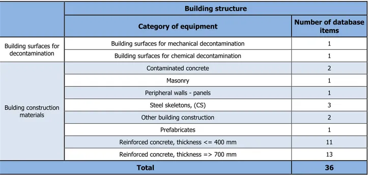
6.1.3.1. Database of buildings ... 40
6.1.3.2. Database of floors ... 40
6.1.3.3. Database of rooms ... 40
6.1.3.4. Database of equipment ... 41
6.2. CALCULATION DATA ... 44
6.2.1. General calculation data ... 45
6.2.2. Calculation data for technological procedures ... 46
7. DEFINITION OF DECOMMISSIONING ACTIVITIES ... 48
7.1. METHODS FOR DEFINITION OF DECOMMISSIONING ACTIVITIES ... 48
7.2. DISMANTLING ACTIVITIES ... 49
7.2.1. Pre-dismantling decontamination ... 49
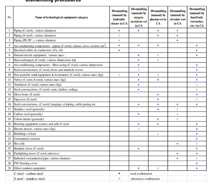
7.2.2. Dismantling procedures ... 50
7.2.3. Decontamination of building surfaces procedures ... 54
7.2.4. Final building RA-survey procedures ... 56
7.2.5. Post-dismantling decontamination of technological equipment ... 57
7.3. WASTE MANAGEMENT ... 57
7.3.1. Radioactive waste management ... 57
7.3.1.1. Technological methods for treatment of solid radwaste ... 58
7.3.1.2. Technological methods for treatment of liquid waste ... 59
7.3.1.3. Technological method for conditioning of RAW to the repository ... 60
7.3.2. Non-radioactive waste management ... 61
7.4. DEMOLITION, SITE RESTORATION AND RELEASE OF SITE ... 62
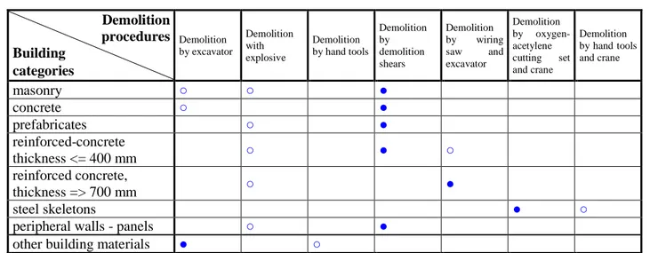
7.4.1. Demolition ... 62
7.4.2. Site restoration ... 63
7.5. MANAGEMENT AND SUPPORT ACTIVITIES ... 64
8. DEFINITION OF WASTE MANAGEMENT SCENARIOS FOR THE ISOTOPE CENTRAL BUILDING IN STUDSVIK ... 66
8.1. WASTE MANAGEMENT SCENARIOS – GENERAL APPROACH ... 66
8.2. WASTE SCENARIOS FOR SOLID RADWASTE ... 67
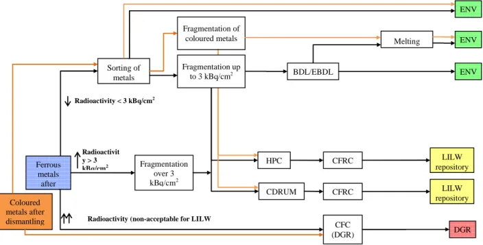
8.2.1. Waste scenario for metal RAW ... 67
8.3. WASTE SCENARIO FOR NON-METAL SOLID RAW ... 69
8.4. WASTE SCENARIO FOR LIQUID RADWASTE ... 70
8.5. GENERAL SCHEME FOR WASTE MANAGEMENT ... 71
9. DEVELOPMENT OF STANDARDIZED DECOMMISSIONING CALCULATION STRUCTURE . 73 9.1. STANDARDIZED COST STRUCTURE – REVIEW ... 73
9.2. METHODS OF IMPLEMENTATION OF STANDARDIZED COST STRUCTURE ... 74
9.3. IMPLEMENTATION OF STANDARDIZED COST STRUCTURE IN OMEGA CODE ... 75
9.4. EXECUTIVE CALCULATION STRUCTURE OF ISOTOPE CENTRAL BUILDING ... 77
11. IDENTIFICATION OF DIFFERENCES IN CALCULATION CONDITIONS RESULTING FROM SWEDISH AND SLOVAK DECOMMISSIONING INFRASTRUCTURE ... 86 12. CONCLUSIONS ... 88 13. ANNEXES ... 89
ABBREVIATIONS
CA - controlled area
CS - carbon steel
EC - European commission
EU - European Union
FRC - fibre reinforced concrete
IAEA - International Atomic Energy Agency LLW/ILW - Low Level Waste/Intermediate Level Waste LRAW - Liquid RAW
NPP - Nuclear power plant
NRC - Nuclear Regulatory Commission
OECD - Organization for Economic Co-operation and Development OMEGA - Oracle Multicriterial General Assessment of Decommissioning
PE - polyethylene
PP - polypropylene
PSL - A Proposed Standardised List of Items for Costing Purposes
RA - radioactive
RAW - radioactive waste SS - stainless steel
REFERENCES
[1] KRISTOFOVA, K. et al., A Model Study of Costs Estimates of Decontamination and Decommissioning with an Emphasis to Derive Cost Functions for Alpha-Contaminated Material Using OMEGA Code, SKI Report 2005:38, December 2004
[2] KRISTOFOVA, K. et al., An Applied Study of Implementation of the Advanced Decommissioning Costing Methodology for Intermediate Storage Facility for Spent Fuel in Studsvik, Sweden with special emphasis to the application of the Omega code, SKI Report 2007:19, January 2007
[3] MÖLLER J., CRONSTRAND P., Ågesta rivningsstudie Uppdatering av underlag för kostnadsberäkningar. T-CKV 08-007. Vattenfall Power Consultant AB, april 2008
[4] IAEA, Decommissioning of Small Medical, Industrial and Research Facilities, IAEA-TRS-414, IAEA, Vienna 2003.
[5] IAEA, Handling, Conditioning and Storage of Spent Sealed Radioactive Sources, IAEA-TECDOC-1145, IAEA, Vienna 2000.
[6] NUCLEAR REGULATORY COMMISSION, “Expiration and termination of licenses and decommissioning of sites and separate buildings or outdoor areas”, Code of Federal Regulations, Title 10, 10 CFR Sec. 30.36, 10 CFR Sec. 40.42, 10 CFR Sec. 70.38, NRC, Washington, DC (2001).
[7] MASSAUT, V., “Decommissioning of nuclear laboratories and other small nuclear facilities”, lecture 13.C, IAEA regional training course, Argonne National Laboratory, IL, 2000.
[8] GRIFFITHS C., Lessons Learned In Decommissioning Laboratory Facilities, Proc. Lessons Learned from the Decommissioning of Nuclear Facilities and the Safe Termination of Nuclear Activities, Athens, 2006.
[9] A Proposed Standardised List of Costs Items for Decommissioning Purposes, OECD/NEA, EC, IAEA, 1999
[10] F.-W. Bach and coll., Handbook on decommissioning of nuclear installations, Nuclear science and technology, European Commission, EUR 16211 EN, 1995
[11] R. Wampach and coll., Decommissioning of nuclear installations, European Commission, 1995
[12] DUFAULT, R. et al., Reducing Environmental Risk Associated with Laboratory Decommissioning and Property Transfer, Environmental Health Perspectives, Volume 108, Supplement 6, pp. 1015-1022, December 2000.
[13] HEDVALL, H.R. et al., Project Evaluation of the Decommissioning of a Laboratory Plant in Studsvik, WM´06 Conference, Tucson, Arizona, February 26-March 2, 2006.
[14] VASKO, M. et al., On tentative decommissioning cost analysis with specific authentic cost calculations with the application of the Omega code on a case linked to the Intermediate storage facility for spent fuel in Sweden, SKI Report 2007:21, March 2007
EXECUTIVE SUMMARY OF THE PROJECT
The Project ‘On cost estimate for dismantling of the Isotope Central’ aims to demonstrate the tentative application of the advanced costing methodology of decommissioning applied to the Isotope Central in Studsvik, using the OMEGA code. The result of the project is a report consisting of 14 chapters. Their content is following:
Chapter 1 Introduction describes the position of laboratories and their decommissioning within nuclear and radiological facilities. Purpose of the Isotope Central building as radiological laboratory is briefly explained. The basic principles of decommissioning costing and advanced decommissioning costing are discussed. The steps how to achieve the aim of the Project are listed.
Chapter 2 Worldwide D&D Approach to Research Laboratories and Hot Cells is based on bibliographic research and represents overview of relevant information accessible. Common features of research laboratories to be decommissioned are discussed. The decommissioning strategy for research facilities and hot cells is described. Then examples of national experience are given covering decommissioning of nuclear laboratories at SCK•CEN (Belgium), decommissioning of nuclear medicine department and radioisotope workplace in the Czech Republic, lessons learned in decommissioning laboratory facilities in the UK, the US approach to reduce environmental risk associated with laboratory decommissioning, and finally on-site experience from laboratory plant D&D in Studsvik.
Chapter 3 Brief Survey of Isotope Central Building is reported. Since no sufficient and relevant input data on Isotope Central Building material and radiological inventory had been accessible, a site walk-down in Isotope Central building has been performed and recorded in the survey report in this Chapter. Survey report contains not only our observations but also information obtained from accompanying Isotope Central staff.
Chapter 4 Description of Decommissioning Cost Calculation Code Omega provides a brief introduction to the computer code OMEGA, developed at DECOM, a.s. This software is an option oriented calculation and optimization code for applications in decommissioning decision making processes for nuclear facilities of various types and radiological properties. The Omega calculation code has been chosen for the performance of cost calculations for Isotope Central Building decommissioning planning and costing.
Chapter 5 Conditions for Tentative Decommissioning Calculations describes what input data have been used for calculation and what scope of decommissioning activities has been taken into consideration. Inventory input data comes from site walk-down because of lack of original information and 3 surface contamination levels as alternatives have been taken into consideration. Labour costs unit factors come out from Swedish conditions. These costs have major influence on overall costs. Other cost unit factors like
prices of materials, chemicals, media, fuel, electricity etc. come from either international or slovak conditions. Manpower unit factors come from international conditions.
Chapter 6 Development of Database for the Input Data Applied in Calculations is based on the room oriented inventory database structure suitable for application of the OMEGA code. The developed data include the data for buildings, floors, rooms and equipment in individual rooms. These data are based on the site walk-down (material data) and on expert estimation (material and radiological data), using also information gathered from similar facilities.
Data include also unit factors and other parameters, mentioned in previous paragraph for Chapter 5.
Chapter 7 Definition of Extent of Decommissioning Activities. Methods for definition of extent of decommissioning activities are presented. The preparatory activities before starting dismantling are given in a tentative extent. The decommissioning activities relevant for room oriented approach are identified, listed and characterised for dismantling, decontamination of building surfaces, final building RA-survey. The activities for site restoration, demolition and release of site are described.
Waste management activities for treatment, conditioning and disposal of individual types of waste as resulted during decommissioning are identified and described.
The management, support activities, maintenance and surveillance activities were developed in a tentative extent.
Chapter 8 Definition of Waste Management Scenarios for Isotope Central Building in Studsvik presents a general approach to waste management scenarios. Following waste management scenarios are presented, as applied in the code OMEGA: waste scenario for solid radwaste (metal RAW and non – metal solid RAW), waste scenario for liquid RAW, and general scheme for waste management.
Chapter 9 Development of Standardized Decommissioning Calculation Structure presents the overview of the standardized cost structure for decommissioning. The general methods and experience from implementation of this structure are described, as well as the implementation of the structure in the computer code OMEGA.
The procedure for development of the standardised calculation structure for the Isotope Central building is also introduced.
Chapter 10 Performing of Tentative Calculations. The tentative decommissioning cost calculations were performed for 3 options which differ in level of contamination of equipment surfaces in order to present the capabilities of the methodology and the code applied and influence of contamination on main output parameters. Following set of parameters was calculated:
• Main decommissioning parameters, such as costs, manpower and collective dose equivalent characterizing each decommissioning option, formatted in standardized structure.
• Results characterizing distribution of materials arisen from decommissioning. • Tentative decommissioning time schedule.
Chapter 11 Identification of Differences in Calculation Conditions Resulting from Swedish and Slovak Decommissioning Infrastructure. Typical identified areas of differences between Slovak decommissioning infrastructure as applied in the tentative cost calculations and Swedish conditions are identified as follows:
• The endpoints for waste arisen from the decommissioning process, unconditional, possible conditional releasing of materials and disposal at available (or planned) repositories (HLW, LLW, ILW, VLLW). • Waste management technologies including their technological parameters.
• Differences in project management, engineering and various support activities. • The local values of cost unit factors.
1.
INTRODUCTION
A significant number of nuclear facilities are smaller sized comparing to nuclear power plants or reprocessing facilities. This includes such installations as radio diagnostic and radiotherapy hospital equipment or laboratories, research facilities and laboratories using radioactive material, hot cell laboratories etc. Decommissioning of these facilities is often seen as a trivial and low priority activity. This may result to underestimating the preparation of decommissioning process and consequently to increase of real costs and possible delays of decommissioning.
It is recognized that the strategies and specific requirements for small facilities may be much less difficult than for large ones such as nuclear power plants or fuel processing facilities. However, many of the same principles may be applied.
In nuclear medicine departments or laboratories unsealed sources are used both for diagnostics and therapy (in vivo techniques). These types of sources are also used in laboratory tests (in vitro techniques). Most medical radionuclides are, however, short-lived and they will decay quickly to acceptable levels.
The Isotope Central Building located in Studsvik, Sweden belongs to this type of facilities. Radioisotopes with short half-lives for diagnostics and treatment were prepared there. These isotopes were produced in nearby reactor R2 in immediate vicinity of the Isotope Central building. The isotopes were transported to the Isotope Central Building and they were modified to required form in its hot cells and laboratory rooms. It is assumed that besides these short-lived radionuclides also the traces of radionuclides with longer half-lives (e.g. cobalt, caesium or alphas) may occur, mainly in contamination of the hot cells and in ventilation systems.
Although the Isotope Central Building is not classified as a nuclear facility, the decommissioning of this facility should come out from the same principles as the decommissioning of nuclear facilities. This also includes an estimation of costs, potential exposure and amount of generated waste arising from the decommissioning process, as well as waste treatment.
The planning and implementation of decommissioning strategies for nuclear facilities requires a careful cost calculation analysis of the whole process. Since the number of decommissioning projects has increased, an application of standardised cost structure within the advance decommissioning costing methodology seems to be a suitable solution how to achieve transparent, traceable and comparable results with various decommissioning projects in various countries. The standardised cost calculation structure for decommissioning was issued and recommended commonly by OECD/NEA, EC and IAEA [9].
The costing methodology used in this Project implements this standardised cost calculation structure. The methodology relays directly on the real inventory of the nuclear installation to be decommissioned (structure, materials, weights of materials, contamination levels, nuclide composition and others). It means, this approach uses the generic costing methodologies and not the comparative costing methodologies. Methodology implements directly also the local factors like labour costs, decommissioning infrastructure including the technologies for dismantling and decontamination, treatment, conditioning and disposal of waste and other technologies for decommissioning. The costing methodology implements the elements which model the real material and radioactivity flow in whole decommissioning process. The radioactivity flow should be nuclide resolved and the radioactive decay for each nuclide should be respected.
For a proper implementation of the advanced generic costing methodology it is necessary to develop the inventory database and calculation databases with structures, which support and enable using the advanced costing methodology.
The advanced decommissioning costing methodology with these properties was developed recently in the company DECOM a.s. and implemented into the computer code OMEGA.
The implementation of the advanced costing methodology and also the use of the computer code OMEGA is country specific or decommissioning project specific. It means that following aspects should be considered: • inventory database for nuclear facility to be decommissioned should be developed with the structure
relevant for the advanced costing methodology,
• local decommissioning infrastructure should be analysed and implemented into the decommissioning scenarios in order to develop/evaluate relevant decommissioning options, specific for the country and for the nuclear installation to be decommissioned,
• local unit factors and other country specific calculation data should be implemented into the calculation database.
Respecting these implementation principles, the advanced costing methodology and also the computer code can be used practically for each nuclear facility in each country.
The main purpose of the presented study is to demonstrate the trial application of the advanced costing methodology using OMEGA code for Isotope Central Building in Studsvik. Within the project, the following activities were carried out in order to perform the tentative decommissioning calculations by OMEGA code: 1) obtain relevant input data on Isotope Central Building, if possible, by studying of available technological
and civil engineer drawings, lists of equipment, radiological records and measures and other documents together with interviewing of involved personnel and visual facility inspection,
2) introduce available information on decommissioning of facilities similar in purpose and size to Isotope Central Building,
3) assemble an inventory database suitable for standardised decommissioning cost calculations including radiological parameters,
4) propose a range of decommissioning calculations and define an extent of decommissioning activities, 5) define a waste management scenario for particular material waste streams,
6) develop a standardised cost calculation structure applied for decommissioning calculation, 7) perform the trial decommissioning calculations by OMEGA code.
2.
WORLDWIDE D&D APPROACH TO RESEARCH
LABORATORIES AND HOT CELLS
It is intended in this section to sum up aspects of decommissioning and gathered published experience from various small nuclear facilities covering medical, industrial and research ones. Emphasize is given to laboratories and hot cells representing small-scale decommissioning projects similar to Swedish Isotope Central Building in Studsvik. Finally, several examples of national experience and valuable lessons learned from various laboratory decommissioning are provided.
2.1
COMMON FEATURES OF RESEARCH LABORATORIES TO BE
DECOMMISSIONED
Research laboratories are typically equipped with fume hoods, gloveboxes and/or hot cells. A wide range of radionuclides may be handled. Fume hoods, gloveboxes and hot cells have connection to an active ventilation system and may also have a connection to an active drainage system. The drains may become contaminated with any or all of the radionuclides that were used in these enclosures. Active drains are therefore an important component of the decommissioning process. The spread of airborne contamination in the ventilation ducts associated with hot cells and gloveboxes is also a potential issue for decommissioning [4].
For decommissioning purposes it is important to record not only the type of contamination (beta, gamma and/or alpha) but also whether the facility was used for mechanical (e.g. cutting) or chemical activities. In case of chemical activities carried out during an operation inside a hot cell or a glovebox the residual material and equipment may be more difficult to decontaminate.
Immediate dismantling is often the optimal strategy for decommissioning of most small facilities to have an opportunity to use the operational staff familiar with the facility. However the strategy depends on type, status of the facility and the presented radioactive waste inventory.
Unfortunately, no action strategy is the common practice for many small facilities with terminated operation, because they can be easily shutdown for periods of non-use or maintenance. The longer periods of no action are, the higher risks of loss of documentation and non availability of the adequate operational history from the former staff leading to higher decommissioning costs undertaken.
2.2
DECOMMISSIONING STRATEGY FOR RESEARCH FACILITIES AND HOT
CELLS
According to IAEA recommendations [4] the selection of a suitable strategy for small facilities is typically simpler than for nuclear power plants or fuel cycle facilities. There may be variations in detail among the strategies for medical, research and industrial facilities and also variations within these types of facility.
It is necessary to take into account in the strategy all the sealed sources if they are included in the shut down facilities. These sources pose significant hazards that must be addressed and alternative exposure scenarios should be considered according to the potential harm the source could cause to workers, the public or the environment.
When a radiation source is no longer to be used for its original purpose, the following management options may be considered [5]:
• transfer to another user for application elsewhere, • return to the manufacturer or supplier,
• storage for decay of sources containing radionuclides with a short half-life, followed by disposal as non-radioactive material,
• transport to a centralized interim storage facility until a conditioning facility is available, • transport to a central conditioning facility, followed by interim storage,
• on-site conditioning of the source followed by interim storage until a centralized storage or disposal facility is available,
• transport of the conditioned source to a disposal facility, if available, • final disposal in a licensed repository.
In general, most of the research facilities exist in industrialized countries. As one example, in the USA the decommissioning of these facilities has received considerable attention. Up to about 1994 there was no clear guidance on when facilities should be decommissioned, and many stood idle for long periods of time [4]. The NRC has more recently amended the license rules to include the timeliness of submitting decommissioning plans and the completion of decommissioning. A maximum delay period of two years after shutdown has been specified by the NRC before it is obligatory to begin the decommissioning process [6]. In European Union there is a tendency to suggest a strategy of immediate decommissioning after shutdown or as soon as possible thereafter if facilities and sites have remained idle for many years. Regulatory requirements and public involvement have forced decommissioning strategies to be addressed.
From the technical point of view, the specific decommissioning activities carried out on research facilities are as follows [4]:
• to remove any potential sources of radiation exposure remaining on the equipment,
• to carry out a preliminary decontamination process to decrease the risks and exposure of the workers during the subsequent decommissioning phases (i.e. at least eliminating removable contamination), • to perform a dismantling of the hot cells and gloveboxes in a ventilation controlled chamber or
protective tent or, for fume hoods, in a controlled area,
• to minimize waste production by addressing appropriate waste management techniques (i.e. recycle and/or reuse, decontamination to meet release criteria or removal as radioactive waste).
It is concluded that the currently preferred decommissioning strategy for contaminated medical, research and industrial facilities is to perform dismantling and decontamination activities promptly with no significant technical problems (in comparison to power reactors and large nuclear facilities) and to store waste in an approved manner until disposal routes become available.
2.3
EXAMPLES OF NATIONAL EXPERIENCE
This section reports several national experience from decommissioning projects carried out and lessons learned to be applied for further similar projects in other countries.
The first provided experience is from a successful project for dismantling a heavily contaminated hot cell, as well as research and development laboratories, carried out by the Belgian Nuclear Research Centre (SCK•CEN), reported in Ref. [7]. The second lessons learned come from the decommissioning of nuclear medicine department and radioisotope workplace in the Czech Republic published in Ref. [4]. The third lessons learned from decommissioning of laboratory facilities represent the summarized experience from various projects within the United Kingdom [8]. The fourth one is the US general system approach to laboratory decommissioning and its application published in Ref. [12]. The last valuable lessons learned come from on-site experience from laboratory decommissioning in Studsvik published in Ref. [13].
2.3.1
Decommissioning of nuclear laboratories at SCK•CEN, Belgium
In addition to several nuclear reactors, the Belgian Nuclear Research Centre (SCK•CEN) in Mol is comprised of research laboratory buildings with hot cells, gloveboxes and fume hoods. These were used for post-irradiation research on fuel and reactor material, tests on fuel reprocessing, the characterization of waste and studies and analyses of the effects of radiation and contamination on animals and plants.
The final goal of the selected decommissioning strategy was to obtain a release for the unrestricted reuse of the site by removing radioactivity as well as keeping valuable non-nuclear infrastructure and equipment. By removing contaminated parts, the building can then be used for new industrial purposes outside the nuclear field. One of the buildings, physics building consisted of laboratories using C-14, Cs-137, Co-60, Ba-133 and Sr-90 radionuclides for experiments and measurements. The total wall and floor surface of these laboratories, including offices and waste storage room covered approximately 700 m2. Average
contamination levels were below 2.5 Bq/cm2, with hot spots of up to 30 Bq/cm2 for beta and gamma
emitters and 0.1 Bq/cm2 for alpha emitters. The radiological characteristics of physics building might be
similar to chosen test decommissioning calculation facility - Isotope Central Building in Studsvik. Decommissioning process consisted from the following activities:
• scanning for alpha, beta and gamma contamination on loose material and equipment inside the controlled area (non-contaminated objects released, potentially contaminated or contaminated items brought to the decontamination area and finally either free released, released with restrictions or treated as radioactive waste),
• the devices anchored to the walls and floors (ventilation pipes, fume hoods, waste-piping) were demolished and removed to the decontamination area for treatment;
• vacuum cleaning and washing the floor and walls;
• mapping all surfaces and contamination was removed by scabbling, shaving and/or drilling; All the surfaces washed again and washwater collected and sampled. In case meeting the release criteria, the demarcation of the zone was removed.
Simple decommissioning tools were chosen, such as standard saws for dismantling, electrical nibblers or shears for ventilation pipes. Contaminated wall plaster, concrete, stone and tiles were removed using electric and pneumatic scabblers and drills.
Decommissioning of hot cell and gloveboxes were performed in the following steps: Preparation – transfer of the waste generated during the operational period. The equipment inside is then dismantled using tongs, manipulators or gloves. The box or the cell is decontaminated (mechanical polishing and vacuum cleaning or high pressure cleaning) after the equipment is dismantled and the waste generated by these activities is removed. An airtight enclosure is constructed around the hot cell or the glovebox to perform its dismantling by disk grinders or plasma arc cutters.
Lessons learned from the project:
1) The decommissioning of contaminated laboratories and hot cells can be carried out simply, with existing tools, provided that the work is efficiently organized.
2) The management and minimization of the generated waste is important, as this part of the operation has a large impact on the total cost of the decommissioning.
3) The characterization before, during and after the operation, to establish the scope of the decommissioning, to sort material by its radioactivity content and to characterize the flow of the material generated during the decontamination.
2.3.2
Decommissioning of nuclear medicine department and radioisotope
workplace in the Czech Republic
A hospital department in which radiopharmaceuticals were administered to patients was moved to a new building after 40 years of operation. It had been decided that the original area would be reused for non-radiological purposes and therefore had to be decommissioned. The work was completed in 1998. Owing to the short half-lives of the radionuclides used, such as Tc-99m, I-131 and others in Table 2-1, it was decided to decommission the building using the delay–decay method. This method involved three major steps [4]: • the transfer of the sources (both opened and sealed) to the new facility,
• the identification of contaminated surfaces and equipment,
• regular checking of the contamination levels of the contaminated surfaces and equipment until they reached the prescribed limit, see Table 2-2.
Table 2-1 Radioisotopes approved for use in the department [4]
Isotope H-3 C-14 P-32 Ga-67 Y-90 Tc-99m
Half-life 12.3 a 5730 a 14.3 d 3.3 d 2.7 d 6 h
Allowed activity 40 MBq 10 MBq 10 MBq 200 MBq 4 GBq 40 GBq
Isotope In-113m I-123 I-125 I-131 Au-198 Tl-201
Half-life [a] 1.7 h 13.2 h 60.1 d 8 d 2.7 d 3 d
Allowed activity 4 GBq 2 GBq 70 MBq 40 GBq 400 MBq 100 MBq
Table 2-2 Summary of contamination checking in the department of nuclear medicine
Checked space and/or item
Surface contamination level at the date of measurement (Bq/cm2)
March 9, 1998 June 5, 1998 August 25, 1998
Floor – female cloakroom <0.5 <0.5 <0.5
Floor – wards 1 <0.5 <0.5
Floor – corridor <0.5 <0.5 <0.5
Floor – isotope application area 1 <0.5 <0.5
Device for emptying urine pots 150 30 <0.5
Air hood 200 40 <0.5
Shower – patients 2 <0.5 <0.5
Floor – male patients' toilet 2 <0.5 <0.5
Toilet bowl – male patients' toilet 3 <0.5 <0.5 Floor – female patients' toilet 1.5 <0.5 <0.5 Toilet bowl – female patients' toilet 3 <0.5 <0.5
The decommissioning plan for medicine department was submitted to the regulator for approval, together with a radiological map of the building. The whole decommissioning process was represented by mainly radiological survey: checking the surface contamination and measurements of the specific radioactivity of the items. The radioactivity of the equipment decayed below the free release limits confirmed by documented measurements, see Table 2-2. Therefore the equipment were free released or treated as non-radioactive waste. Based on the radiological survey completed in the building, a proposal for its release for unrestricted use was submitted to the regulator.
However the decommissioning process of the State Radiological Institute where research activities were carried out was a bit more complicated due the remaining contamination estimated at 100 GBq principally caused by H-3, C-14, Co-60, Sr-90, Cs-137, Ra-226 and Am-241. Performed decommissioning activities of the building involved [4]:
• the detailed mapping of contaminated areas, surfaces and movable items,
• the creation of a new support area for decommissioning personnel and a new laboratory for personal dosimetry (installed new cloakrooms, showers, dosimetry and administrative spaces),
• the decontamination of the radioisotope laboratories,
• the dismantling of equipment (e.g.: air hoods, alpha boxes),
• the systematic decontamination of all surfaces and equipment to be left on the site (using wet and non-invasive mechanical processes),
• an evaluation of the effectiveness of the decontamination,
• the submission of an application for the release of the building for non-radioactive uses (i.e. closing down the radioisotope workplace).
All equipment released from the building was monitored for contamination before being disposed of at a municipal dump or in the repositories of Bratrství and Richard (when found to be contaminated with radium and with other isotopes, respectively). Some larger items contaminated with radium were placed in the disposal pond of a uranium ore milling plant.
The Ra-226 isotope was identified as the principal source of the contamination. In order to remove contamination from structural materials it was necessary to demolish large volumes of material, including: plaster, flooring and fill layers removed, excavated contaminated soil in the basement. These were disposed of as radioactive waste. Subsequent confirmatory measurements showed that, in all the affected places, contamination by Ra-226 and its progeny was below regulatory limits and the building was free released for other reuse.
Lessons learned from the projects:
1) The operation of older facilities is not usually well recorded and therefore whenever possible a member of the original staff should be involved in planning and/or performing the decontamination and dismantling of a facility.
2) Skilled and experienced personnel should be involved in planning and implementing a decommissioning. 3) The more information is recorded and retained about the technical and radiological aspects of the
decommissioning of a facility the better for managing future cases.
2.3.3
Lessons learned in decommissioning laboratory facilities, UK
A comprehensive decommissioning plan is necessary even for the decommissioning of small facilities if costly delays and errors are to be avoided. Often a small nuclear laboratory engages the services of a specialist decommissioning company to carry out some aspects of the decommissioning plan.
It is never too soon to consider the need for decommissioning and the records that will facilitate such action. Lessons learned from past projects have identified how making assumptions without validating them can result in protracted delays and escalating costs not originally envisaged [8].
Lack of finance should not be used as an excuse to avoid making progress with decommissioning.
Supervision of an experienced decommissioning consultant contributes to keeping the overall costs of decommissioning as low as possible. (e.g.: contractor to carry out dismantling/demolition works, the cutting up of dismantled materials into manageable pieces for further characterization and radionuclide activity quantification, etc.). Such experts can provide training to the existing work staff (e.g.: to enable existing staff to characterize and quantify the waste, especially those that are suitable for free release). The
confidence to decide that waste can legitimately be free released to a landfill site or scrap metal for recycling can dramatically reduce the overall costs.
Early discussions with the regulatory bodies are to be encouraged, as well as with stakeholders and residents to avoid generating unnecessary concern. Providing information during the whole decommissioning process is helpful to all parties.
The owners of small laboratories scheduled for decommissioning often have no previous relevant experience, so that a ‘lessons learned’ program from other similar facilities is very useful and cost and time-effective.
Wherever possible, simple, tried and tested techniques and tools should be applied throughout the decommissioning project, especially for decontamination techniques as part of waste minimization.
2.3.4
The US approach to reduce environmental risk associated with
laboratory decommissioning
In order to mitigate environmental risk and reduce financial liabilities associated with laboratory decommissioning a functioning system, environmental due diligence auditing, has evolved over time and used by organizations. This system involves a 4-phase approach to identify, document, manage and clean up areas of environmental concern [12]. Environmental due diligence auditing includes:
• historical site assessment, • characterization assessment, • remedial effort,
• final status survey.
Phase I: Historical Site Assessment is undertaken to identify potencial areas of environmental concern, including contamination. Four processes are conducted to track various uses of hazardous substances in the laboratory:
1) interviews with the current property owner, 2) a review of documents and records,
3) a site visit to observe the current uses,
4) a written report to document Phase I findings, observations and recommendations.
The result of the report should determine either the potential contamination exists or not.
Phase II: Characterization Assessment
Potential areas of contamination identified in the Phase I are evaluated by sampling and analyses. These should provide extent of contamination and if the contaminant is present at levels above the clean up or release criteria and remedial effort is necessary or not. Instruments e.g., Geiger-Mueller counters,
destructive sampling techniques and environmental media sampling are used. All findings and recommendations including whether remediation is necessary should be documented in a Phase II report.
Phase III: Remedial Effort
If the laboratory is contaminated by hazardous substances resulting to unreasonable risk to human health or environment, decontamination must be applied. The selection of decontamination method depends on the nature of contamination (radiation, microbiological, chemical), specific contaminant and contaminated surface (impervious vs porous, structural vs nonstructural). Decontamination can lead to complete removal of contaminated surface/structure for disposal (e.g. asbestos containing materials), stripping off a contaminated layer from the surface (scabbling devices are used) or cleaning (washing by solvents, vacuuming, brushing). Once a decontamination method is selected, a decontamination plan is prepared. After the plan has been implemented, the decontamination methods must be documented in a Phase III report.
Phase IV: Final Status Survey is to document the final conditions of the laboratory after remediation has been completed. For a remedial effort involving radioactive contamination, the U.S. Department of Energy has developed a certification protocol, the Multi-Agency Radiation Survey and Site Investigation Manual (MARSSIM). However there is no standard for final status survey for remedial effort involving chemical contamination [12].
Application of environmental due diligence auditing system for laboratory decommissioning contaminated by H-3, C-14 and I-125 radionuclides
Phase I: H-3, C-14 and I-125 are routinely used in a biomedical research laboratory on benchtops, in chemical hoods and sometimes spilled on floors or dumped in sinks.
Phase II: Areas to survey include benchtops, hoods, gloveboxes, sinks, floors surfaces. Sink drains and waste disposal areas. Potentially contaminated surfaces can be located beneath the floor tiles and behind the hoods. Survey techniques are represented by surface scanning, direct measurements of surface activity and smears. A Geiger Mueller detector can be used for C-14, sodium iodide detector for I-125. Smears are used to measure removable activity from these contaminants by liquid scintillation counting. It is necessary to know the acceptable release criteria for these radionuclides.
Phase III: A decontamination plan ranging from simple techniques (washing, wiping surfaces) to equipment removal (hoods or sink drain lines). H-3 is difficult to completely decontaminate (it diffuses into surfaces and offgases from these surfaces), I-125 is volatile, so contamination can be widespread in the laboratory especially on metal surfaces.
Phase IV: The final status survey can be planned using the MARSIIM. The same survey techniques used to characterize contamination can be used also to demonstrate meeting the release criteria.
2.3.5
On-site experience from laboratory plant D&D in Studsvik
The decommissioning of the former nuclear Active Chemical Laboratory plant (ACL) and Active Chemical Filter building (ACF) performed by AB SVAFO had been under way since 1998. In 2005, an application for free release of the buildings was made.
The ACL building with more than 70 glove boxes was used as a research facility reprocessing spent fuel, for material testing in hot cells, production of radiation sources and storage of fissile materials. The ACF building was a filter and ventilation building for radioactive air streams from the ACL laboratory. Both buildings were contaminated mainly by Co-60, Cs-137, Sr-90, H-3 and transuranic nuclides such as Pu and Am [13].
At the start of decommissioning, the authority had no clear directives for free release limitations. Therefore specific decommissioning clearance levels were decided to use for the performance of the project, see Table 2-3.
Table 2-3 Specific Decommissioning Clearance Levels for ACL [13]
Nuclide Activity (kBq/m2) Co-60 1E+01 Cs-134, 137 1E+02 Sr-90 1E+03 H-3 1E+05 Pu-238, 239, 240 1E+01 Am-241 1E+01 Pu-241 1E+03
As for the surface final survey, one sample was taken per 1 m2 of floor and wall up to 2 m. Above this level
and on the ceiling, one sample was taken per 4 m2. Manual hand-held dose rate instruments were used and
as a complementary check, 8-hour measurements with an in-situ gamma spectrometry technique were used. Produced decommissioning waste was divided into these streams:
• combustible waste was sent to incineration facility in Studsvik,
• scrap metal (steel and aluminium) was sent to the melting facility (95% of the metals were free released as ingots),
• removed concrete, asbestos and insulating materials were deposited at a community dump,
• mixed waste in 200 l drums were sent to interim storage (crushed concrete and dust, PVC linoleum, rubber and glass.
Lessons learned from the decommissioning of the former nuclear Active Chemical Laboratory plant (ACL) performed by AB SVAFO concerning planning, organization, management and used instrumentation, are summarized form Ref. [13]:
1) There have to be check routines in place to be in compliance with timetable and at the same time maintain the quality of the work performed.
2) Strong partnership purchaser-contractor is important to deal with unexpected events during decommissioning.
3) An action plan for staff turnover for free releasing and decontamination work is necessary. 4) The strategy for cost evaluation is the key issue.
5) An advantage of open dialogue with authorities with prepared communication plan. 6) Updated drawings available and exchange of experience are essential to project planning.
7) The choice of measurement instrumentation had an effect on efficiency. The gamma in-situ spectrometry had several benefits, such as: discovery of sub-surface contamination not detectable with hand-held equipment and should have been used also during pre-studies.
3.
BRIEF SURVEY OF ISOTOPE CENTRAL BUILDING
The Isotope Central Building is a radiopharmaceuticals preparation facility. The Isotope Central Building started its operation in 1960; a termination of operation was in June 2005.The main activity during the operation of the Isotope Central Building was the preparation of a broad range of about 200 radioisotopes with short half-lives (e.g. I-125, P-42, P-43, Ir-192). These nuclides were produced in the reactor R2 in the vicinity of the Isotope Central Building. The isotopes were transported to the Isotope Central Building by tube post and they were modified to required form in hot cells, fume hoods and glove boxes within laboratory rooms. It is assumed that short-lived radionuclides are no more present in current contamination of the Isotope Central Building equipment but pollutant radionuclides with longer half-lives such as cobalt, caesium or alphas will occur, mainly in contamination of air ducts of active ventilation from hot cells, fume hoods, glove boxes and in tube post system.
According to Swedish categorization of institutions / facilities dealing with radioactive materials, the Isotope Central Building is considered to be a ‘non nuclear facility’. The categorization itself depends on many factors, including operational history, chemical substance and nature of radio-nuclides having been presented or being presented, their total/specific radioactivity, encapsulation, types of activities having been performed with radioactive materials.
Neither a spent nuclear fuel has been handlednor liquid radioactive waste has been stored in the area of the Isotope Central Building. Contamination is presented on some constructions and in some equipment.
The decommissioning process is expected to be performed in two phases:
• 1st phase represents decommissioning, including release of the building out of radiological control, without demolition,
• 2nd phase represents demolition of the Isotope Central Building, remediation of site.
Each level of decommissioning strategy development, and consequently decommissioning parameters estimation/calculation, need some appropriate level of knowledge of input data, i.e. qualitative and quantitative information on building and technology to be decommissioned.
Since such collated input data (drawings, figures, parameters of civil construction and equipment to be decommissioned) have not been available for us, a site visit to make a very brief look over the AB Studstvik Isotope Central premises, has been performed. A limited number of rooms, assuming the rooms with the most contaminated equipment having been included, were visited, as well as the corridors. Another source of information was interviewing involved persons during the site visit of the Isotope Central Building.
There is a short output coming from our brief look over, in the next few paragraphs. This description does not cover all the rooms of the Isotope Central premises.
General remarks
Assumed outer dimensions of building are 30 x 15 x 12 m. Isotope Central Building consists of four floors – basemen, 1st floor, 2nd floor and attic. On these floors, elevator, corridors, laboratories, offices and service rooms are situated.
There are six hot cells in the Isotope Central Building, three of them are higher contaminated. The level of contamination has not been available.
Poly-chloride biphenyls were measured close to windows frames. The results were negative.
Asbestos can be expected within the premises. Possible sources of asbestos are the fire-protection door (asbestos covered by iron sheet on both sides), roof covering, cupboards, insulation and black glue located under the floor covering.
Basement
The floor is covered by a dense oil paint.
Corridor
There is an old pipe channel/duct under the floor through the whole length of the corridor. The surface of the pipe channel/duct is non-contaminated. There is a pipeline in the pipe duct with highly contaminated surface due to liquid radioactive waste. Therefore, the lower part of the pipe duct is covered by the steel slabs, and the slabs are grouted with the concrete layer. The upper part of the pipe duct over the concrete layer houses 2 plastic pipelines of diameter 10 cm, 15 cm respectively, low contaminated; and 1 stainless steel pipeline of diameter 8 cm, higher contaminated. The upper part of the pipe duct is covered by the concrete slabs in the corridor. The pipe duct branches to several rooms from the corridor.
The corridor houses a cable duct with lot of cables and a pipe duct/channel right-angle bending to the reactor building (R2), estimated length of which is 7 m. There is a significant amount of cables under the ceiling. A lift is located at the end of the corridor, connecting all the storeys. The majority of the contamination is allocated in the basement.
New laboratory
Plain concrete floor, walls covered by washable wallpapers, ceiling made of concrete slabs. Estimated size is 6 x 8 x 4 m. The room contains only dismantled parts of the hot cell which was operated in the room. The room was planned to house new equipment to run new business; however, the process is currently stopped.
E-003
The room contains office furniture (tables & chairs), lab tools and 2 fume hoods. Preparation of radioisotopes P-42, P-43 (protein markers) was performed in this room.
E012
The vault of dimensions approx 3.5 x 3.5 m houses a tube-post outlet and the fixed store positions for samples sent by tube-post, so called ‘magazines’. There is also an iron shielding door of thickness approx. 70 cm.
The samples were adopted here from the reactor via the tube-post, then stored and consequently sent off again via the tube-post to the hot cells. The tube-post branches also to the laboratory next to this vault.
E-013
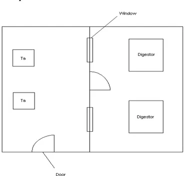
A rough layout of the room is shown in the
Figure 3-1. Preparation of radioisotopes I-125 was performed in this room.
E-002
The room contains 1 large hot cell (3 x 2 x 2.5 m), 2 small hot cells (1 x 1 x 1 m) and a portal rail crane. The room was reviewed from the door-sill. There was an aluminium barrier in the doorframe up to height of 30 cm from the door-sill. A smear sample should exists, however information on contamination level is not available.
Figure 3-1 Simplified layout of the room E-013
Ground floor (comprises approx 10 rooms) Corridor
116 A
The room contains a hot cell, which is higher contaminated, 2 portal cranes (each of lifting capacity 1.5 ton), 2 cranes (each of lifting capacity 1 ton).
The floor is covered by polyester-laminate. The walls are slightly oil-colour painted. There are laboratory desks and residual laboratory tools.
The hot cell (approx 3 x 2 x 2.5 m) consists of iron skeleton filled with lead blocks of width approx. 30 cm. There are also 2 lead-glass eye-sights and 2 two-handed stainless steel manipulators in the hot cell. The lead inner surface of the hot cell is covered by a cracked plastic covering. The hot cell houses also aluminium grates and tools, measuring glasses and test-tubes.
A tube-post is contaminated.
Offices
3 offices were visited. There is a linoleum floor, concrete ceiling with aluminium soffit and pipelines.
1st Floor E204
There are 2 fume hoods, 1 box made of lead shielding blocks (80 x 80 x 80 cm), a tube-post control panel, a bunch of pipes of the tube-post, laboratory desks, 1 ceramic sink.
The floor is covered by linoleum. The walls are slightly oil-colour painted. An aluminium soffit is on the ceiling.
E 205
This is a laboratory room housing 3 fume hoods having been used for radiological measurements. The floor is covered by linoleum. The walls are oil-colour painted. An aluminium soffit is on the ceiling.
E 206
The room was used as a laboratory; in the time of visit it was empty. The floor is covered by linoleum.
E 208
The room was used as a larger laboratory. In the time of visit it was used as a temporary store of material, which will be removed prior to decommissioning. There are also 4 laboratory desks.
Offices
Further rooms on the 1st floor are supposed to be offices. Not visited.
Attic
The floor and walls are covered by a rough concrete without any additional covering. The ceiling is made of porous concrete. 7 doors were identified at the attic.
E304
The floor is thick-painted, the walls are common painted. The ceiling is made of porous concrete panels, the height of ceiling is approx 2.5 m.
There is also a zinc-covered sheet piping of diameter 30 cm. Vent tubes are made of either ferrous sheet or plastic.
This is a passable room to the store room, where RA waste is stored in the small steel sheet drums with lids, each of volume approx 25 l; tens of drums are stored there. The drums contain rags, textiles, plastics, plastic foils, and stainless steel joints.
E 305
The floor is covered by polyester-laminate, the walls are oil colour-painted. The ceiling is made of porous concrete panels; the height of ceiling is lowered against the corridor.
This is a ventilation machinery room providing ventilation for common rooms. A contamination is low level. The plastic piping which diameter is 50 cm and higher, prevails over the ferrous sheet piping. There are also filter drums (10 pcs, diameter 0.75 – 1 m), wooden skeleton filter cartridges, 2 big blowers including electro-motors (power approx 10 kW) and 1 small blower including electro-motor (power approx 5 kW).
E 306
The floor and walls are covered by oil-colour painting. There is a fire protection door with asbestos slab (1.3 x 2.5 m).
This is a ventilation machinery room providing ventilation for medium and higher contaminated rooms and facilities (e.g. hot cells).
Approximately 90 % of vent tubes are made of ferrous sheet (rectangular cross-section, approx
1 x 0.4 m).The rest of vent tubes are made of plastic of diameter min 50 cm. There are several big rectangular filters.
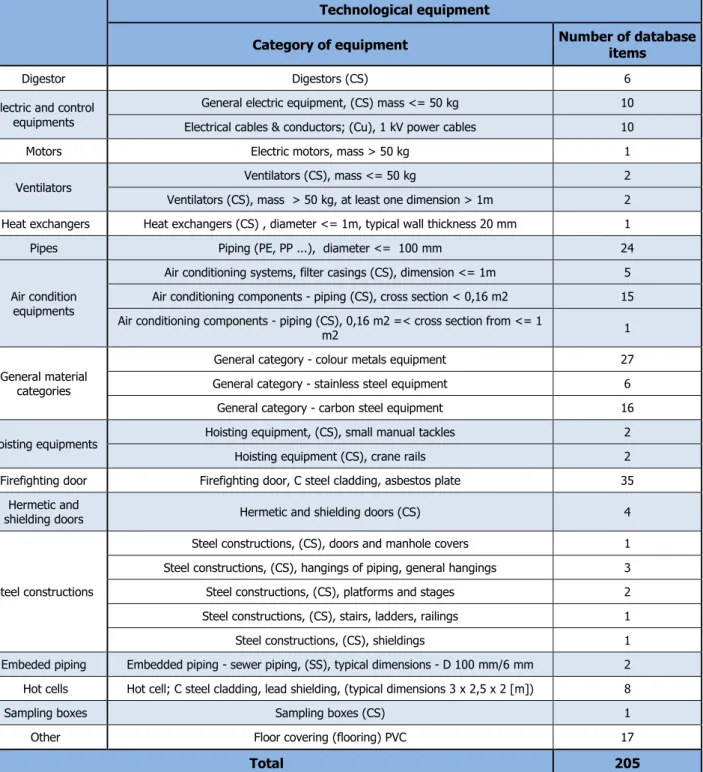
The above mentioned facts obtained from walkdown of the facility and interviewing operational personnel in the Isotope Central Building together with professional assessment of equipment types, material amounts
and composition and physical parameters were used for creation of model inventory database described in Chapter 6.
4.
DESCRIPTION OF DECOMMISSIONING COST CALCULATION
CODE OMEGA
For the performance of cost calculations for Isotope Central Building decommissioning planning, the Omega calculation code has been chosen.
The computer code OMEGA, developed at DECOM, a.s., is an option oriented calculation and optimization code for applications in decommissioning decision making processes for nuclear facilities of various types and radiological properties with following purposes:
1) Definition of the set of decommissioning calculation options according to the standardised structure for facilities with various building and technology inventory structure and with various radiological parameters.
2) Calculation of costs and other decommissioning parameters (such as manpower needs, collective effective dose, waste distribution from decommissioning process etc.) for individual calculation options, for calculated data processing and evaluation.
3) Optimisation of individual calculation options and waste management within the individual options. 4) Comparison of options and selection of the most suitable one based on multi attribute analysis.
Basic properties of the calculation code OMEGA for applications on the level of the calculation options [1]: • Activity based costing was implemented, based on the Proposed Standardised List of Costs Items (PSL)
[9] issued commonly by OECD, IAEA and EC which enables to use the code for various types of nuclear facilities.
• Automatic generation of the standardised calculation structure based on the template calculation structures, and conditions defined by the user and based on inventory data. This automatic generation of the calculation options facilitates significantly the multi option work.
• The code was originally developed for Jaslovske Bohunice A-1 NPP costing with complicated radiological situation. A new concept of calculation modelling of material and radioactivity flow control was implemented in order to increase the accuracy of calculation and for optimisation of radioactive waste management. The code can be used for facilities with various radiological states. The accuracy of calculation of decommissioning parameters is significantly higher then using the traditional costing methodologies where the amounts of waste are estimated.
• The calculation process is nuclide-resolved. This enables to use limits on the nuclide level for treatment / conditioning / disposal / release (unconditional and conditional) of materials as well as calculation of the radioactivity decay to study the effect of deferred activities.
• On-line optimisation of decommissioning options in standard Microsoft Project software using the work breakdown structure, constructed as the upper layer over the standardised structure.
The pre-requisite for efficient work with the OMEGA code is the inventory database of the facility with relevant systems, buildings and radiological data and the calculation database with relevant data for processes, profession / work time data, material / nuclide data and other data.
Main calculated parameters are costs in standardised structure, manpower and exposure items (total values and profession resolved items), material items and nuclide resolved radioactivity items linked to these material items (so called waste distribution), time parameters such as starts and duration of elementary activities and of phases of the process and equipment planning items.
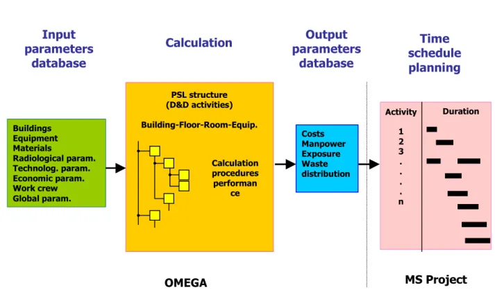
Based on described features of OMEGA code decommissioning calculation a simplified scheme of OMEGA data processing can be created:
Figure 4-1 Simplified scheme of OMEGA data processing
Figure 4-1 identifies input/output data, decommissioning process calculation and its time schedule planning. Displayed OMEGA input database applied in decommissioning calculations for Isotope Central Building are characterised in detail within Chapter 3.
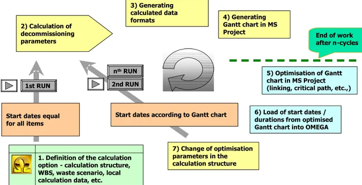
The work with OMEGA for management of the decommissioning calculation option has an iterative character with following main steps displayed on Figure 4-2:
1) Definition of the calculation option in the scope of calculation structure, WBS, waste scenario, local calculation data, extent of calculation, etc.
2) Calculation of parameters in the first calculation runs with start dates equal each other. 3) Generating the calculated data formats.
4) Generating the Gantt chart in MS Project.
5) Optimisation of the Gantt chart in MS Project (linking, critical path, etc.,).
Input
parameters
database
Calculation
parameters
Output
database
Time
schedule
planning
Buildings Equipment Materials Radiological param. Technolog. param. Economic param. Work crew Global param. PSL structure (D&D activities) Building-Floor-Room-Equip. Calculation procedures performan ce Costs Manpower Exposure Waste distribution Activity Duration 1 2 3 . . . . nOMEGA
MS Project
6) Load of start dates / durations from optimised Gantt chart into OMEGA, change of optimisation parameters in the calculation structure.
7) Calculation of decommissioning parameters with start dates derived from the Gantt chart, calculation of optimised decommissioning option. Repeated calculations with start dates derived from Gantt chart up to achieving the finally optimised decommissioning option ready for multi-attribute analysis of individually calculated / optimised / evaluated projects.
Figure 4-2 Graphical interpretation of main steps of the iterative work with Omega
Principles of algoritmisation of costs calculation in the Omega code can be summarised as follows: 1) What to do - management of the standardised calculation structure. Definition of
decommissioning activities and extent of calculation,
2) How to do - management of calculation conditions. Definition of calculation procedures, definition of local calculation input data and correction factors,
3) In what sequence management of material/radioactivity flow in decommissioning by definition of calculation sequence and by data linking of calculation procedures (calculation modelling of decommissioning process), 4) At what time - management of time in decommissioning by on-line optimisation of
decommissioning time schedule with feed-back to the calculation structure supported by dynamical recovery of radiological parameters.
1. Definition of the calculation option - calculation structure, WBS, waste scenario, local calculation data, etc. 1st RUN
2) Calculation of decommissioning parameters
2nd RUN
Start dates according to Gantt chart 3) Generating calculated data formats 4) Generating Gantt chart in MS Project 5) Optimisation of Gantt chart in MS Project (linking, critical path, etc.,)
6) Load of start dates / durations from optimised Gantt chart into OMEGA
7) Change of optimisation parameters in the calculation structure Start datesequal
for allitems
End of work after n-cycles
nthRUN
1. Definition of the calculation option - calculation structure, WBS, waste scenario, local calculation data, etc. 1st RUN
2) Calculation of decommissioning parameters
2nd RUN
Start dates according to Gantt chart 3) Generating calculated data formats 4) Generating Gantt chart in MS Project 5) Optimisation of Gantt chart in MS Project (linking, critical path, etc.,)
6) Load of start dates / durations from optimised Gantt chart into OMEGA
7) Change of optimisation parameters in the calculation structure Start datesequal
for allitems
End of work after n-cycles
![Table 2-1 Radioisotopes approved for use in the department [4]](https://thumb-eu.123doks.com/thumbv2/5dokorg/3351423.19071/19.892.82.813.178.336/table-radioisotopes-approved-use-department.webp)
![Table 2-3 Specific Decommissioning Clearance Levels for ACL [13]](https://thumb-eu.123doks.com/thumbv2/5dokorg/3351423.19071/23.892.91.811.495.695/table-specific-decommissioning-clearance-levels-acl.webp)