SCHOOL OF INNOVATION, DESIGN AND ENGINEERING
VÄSTERÅS, SWEDEN
Advanced Project in Computer Science – DVA443 (30 ECTS)
Model-based approach for automatic
generation of IEC-61025 standard
compliant fault trees
Enrique Zornoza Moreno
ezo17001@student.mdh.se
Examiner:
Barbara Gallina
Mälardalen University, Västerås, Sweden
Examiner:
Radu Dobrin
Mälardalen University, Västerås, Sweden
Supervisor:
Zulqarnain Haider
Mälardalen University, Västerås, Sweden
Enrique Zornoza Moreno Model-based approach for automatic generation of IEC-61025 standard compliant fault trees
Abstract
Reliability and safety of complex software-intensive systems are proved to be a crucial matter since most of these systems fulfil tasks, where a failure could lead to catastrophic consequences. For example, in space systems such as satellites, a failure could result in the loss of the satellite. Therefore, a certain level of reliability and safety must be assured for such systems to trust the services they provide. Standards set this level and put requirements for the analysis and assurance of these properties using documented evidence. In particular, European Cooperation for Space Standardization (ECSS) standards for space systems require Fault Tree Analysis (FTA) for identifying the causes of system failure and consequently safety hazards, as well as fault trees as evidence for the assurance of reliability and safety.
In this thesis, we present a tool supported model-based approach to generate fault tree automatically from an existing system modelling and analysis toolset. CHESS is a system and dependability modelling toolset and integrates Concerto-FLA to enable the support of failure logic analysis. We proposed a model-based transformation from Concerto-FLA to fault tree model and implemented it as an Eclipse plugin in CHESS toolset. A case study is performed in the aerospace domain; more specifically we modelled Attitude Control System (ACS) and automatically generated ECSS-compliant fault trees.
3
Table of Contents
1.
Introduction ... 8
1.1.
Motivation ... 8
1.2.
Context ... 8
1.3.
Contribution ... 8
1.4.
Document structure ... 9
2.
Background ... 10
2.1.
Complex Software Intensive Systems ...10
2.2.
Model-Driven Engineering ...11
2.2.1.
Model-driven architecture (MDA) ... 11
2.2.2.
Model-driven development (MDD) ... 12
2.2.3.
MDE principles ... 13
2.2.4.
Model transformations types ... 14
2.2.5.
Epsilon Transformation Language (ETL) ... 14
2.3.
Component-based software engineering ...15
2.4.
CHESS toolset ...16
2.5.
Dependability modelling and analysis approaches ...17
2.5.1.
Dependability concepts ... 17
2.5.2.
Dependability analysis approaches ... 18
2.5.3.
Concerto-FLA ... 19
2.6.
Fault Tree Analysis ...20
2.6.1.
Graphical Elements ... 21
2.6.2.
Fault tree generation process ... 22
2.6.3.
Cut set ... 22
2.6.4.
Quantitative vs qualitative FTA ... 23
3.
Related Work ... 24
4.
Scientific Method ... 26
5.
Problem Formulation ... 27
5.1.
Problem formulation ...27
5.2.
Problem analysis ...27
6.
Automatic fault tree generation from system models ... 28
6.1.
Which existing failure analysis technique can be exploited to enable automatic
generation of fault tree using model-based approaches according to the current state of the art?
28
6.2.
Which will be the structure of the meta-models required for automatic generation of
fault trees? ...29
6.2.1.
Source meta-model: FLAMM ... 29
6.2.2.
Target meta-model: EMFTA ... 30
6.3.
How to implement the automatic generation of fault tree in CHESS framework? ...32
6.4.
Proposed solution: Automatic FT generation ...33
6.4.1.
M2M transformation algorithm ... 33
Enrique Zornoza Moreno Model-based approach for automatic generation of IEC-61025 standard compliant fault trees
7.
Case Study ... 47
7.1.
Attitude Control System (ACS) ...47
7.2.
ECSS-compliant FT ...48
7.3.
Failure logic analysis of ACS and fault tree generation ...49
7.4.
Discussions ...58
8.
Conclusions and future work ... 59
8.1.
Summary ...59
8.2.
Limitations and future work ...59
5
List of figures
Fig. 1: Relation between MDA, MDD and MDE [30]. ... 11
Fig. 2: MDA portability [1]. ... 12
Fig. 3: MDA transformations [2]. ... 12
Fig. 4: OMG layered MDA [32]. ... 13
Fig. 5: ETL abstract syntax overview [39]. ... 15
Fig. 6: ETL concrete syntax example [39]. ... 15
Fig. 7: ETL pre and post block concrete syntax [39]. ... 15
Fig. 8: Relation between component and interfaces [5]. ... 16
Fig. 9: Error propagation in a system [7]. ... 17
Fig. 10: Dependability and security attributes [7]. ... 18
Fig. 11: Concerto-FLA process [13]. ... 20
Fig. 12: FPTC rules syntax [5]. ... 20
Fig. 13: FT generation procedure based on [19]. ... 22
Fig. 14: Scientific method used in this thesis based on [48]. ... 26
Fig. 15: FLA Meta-model [40]. ... 29
Fig. 16: EMFTA meta-model [43]. ... 30
Fig. 17: EMFTA tool example of FT [43]... 31
Fig. 18: EMFTA representation of event types [42]. ... 31
Fig. 19: CHESS component implementation example [4]. ... 32
Fig. 20: FLA rules syntax example [40]... 33
Fig. 21: Flowchart of FLAMM to EMFTA transformation. ... 35
Fig. 22: ETL code for FTAModels generation. ... 40
Fig. 23: ETL code for top-event creation. ... 41
Fig. 24: Population algorithm ETL implementation for case 1. ... 41
Fig. 25: Plugin appearance. ... 42
Fig. 26: Selection of source model implementation. ... 42
Fig. 27: UI for source file selection. ... 43
Fig. 28: Creation of ETLModule and file parsing. ... 43
Fig. 29: EMFModels configuration Java method. ... 44
Fig. 30: Module configuration and execution. ... 44
Fig. 31: Clear of module and models. ... 44
Fig. 32: Introduced changes in visualizer class (1). ... 45
Fig. 33: Introduced changes in visualizer class (2). ... 46
Fig. 34: Plugin visualizer implementation. ... 46
Fig. 35: ACS software functions [47]. ... 48
Fig. 36: Structure of ECSS standards [52]. ... 49
Fig. 37: Methodology followed in the case study. ... 50
Fig. 38: ACS data-flow. ... 51
Fig. 39: ACS system modeled in CHESS ML. ... 51
Fig. 40: Scenario 1 failure behaviour for FeedforwController. ... 52
Fig. 41: Scenario 1 modelled system annotated with Concerto-FLA results. ... 52
Fig. 42: Concerto-FLA results in CHESS. ... 52
Fig. 43: Scenario 1 result top section of FTAModel. ... 53
Fig. 44: Scenario 1 result bottom section of FTAModel ... 54
Fig. 46: Rule for PD Controller. ... 55
Fig. 45: Rule for FeedforwardController. ... 55
Fig. 47: Scenario 2 modelled system annotated with Concerto-FLA results. ... 55
Fig. 48: Scenario 2 results top section FTAModel. ... 56
Enrique Zornoza Moreno Model-based approach for automatic generation of IEC-61025 standard compliant fault trees
List of tables
Table 1: FT standard events. ... 21
Table 2: FT standard static gates. ... 21
Table 3: FT standard dynamic gates. ... 21
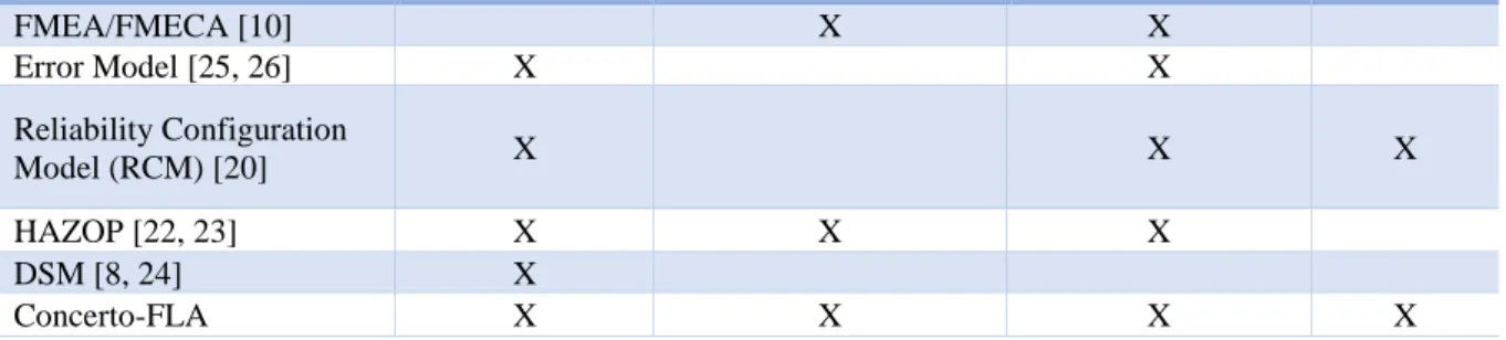
Table 4: Comparison of methods used to derive failure information. ... 28
Table 5: Mapping between the source and target meta-model’s elements. ... 34
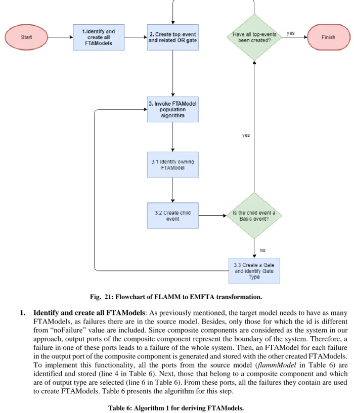
Table 6: Algorithm 1 for deriving FTAModels. ... 35
Table 7: Algorithm 2 for port transformation and FT population. ... 36
Table 8: Algorithm 3 for FTPopulation. Case 1. ... 37
Table 9: Algorithm 3 for FTPopulation. Case 2. ... 38
7
Acronyms and Abbreviations
AADL Architecture Analysis and Definition Language
ACS Attitude Control System
CBSE Component-Based Software Engineering
CHESS Composition with Guarantees for High-integrity Embedded Software Components Assembly
CHESS ML CHESS Modelling Language
DFT Dynamic Fault Tree
ECSS European Cooperation for Space Standardization
EMF Eclipse Modelling Framework
EMFTA EMF-based Fault Tree Analysis
Epsilon Extensible Platform of Integrated Languages for mOdel maNagement
ETL Epsilon Transformation Language
HAZOP Hazard and Operability
FLA Failure Logic Analysis
FLAMM Failure Logic Analysis Meta-Model
FMEA Failure Mode and Effect Analysis
FMECA Failure Mode and Effect and Criticality Analysis
FPTC Fault Propagation and Transformation Calculus
FT Fault Tree
FTA Fault Tree Analysis
IEC International Electrotechnical Commission
ISO International Organization for Standardization
M2M Model-to-Model
MARTE Modelling and Analysis of Real Time and Embedded systems
MDA Model-Driven Architecture
MDE Model-Driven Engineering
MDD Model-Driven Development
MOF Meta Object Family
OMG Object Management Group
SASM Sun Acquisition and Survival Mode
SFT Static Fault Tree
Enrique Zornoza Moreno Model-based approach for automatic generation of IEC-61025 standard compliant fault trees
1. Introduction
In this chapter, the content provided by this thesis is introduced. Section 1.1 discusses the primary motivation for the thesis. Section 1.2 presents the context in which this thesis is developed, and then Section 1.3 describes which are the main contributions provided by our work. Lastly, Section 1.4 shows the overall organisation that this thesis follows.
1.1. Motivation
High-integrity, cyber-physical embedded systems are becoming complex due to the growing demand for new functionalities and recent digitalisation trend. This digitalisation is targeting diverse domains, e.g., automotive industry, space systems, railway systems, avionics and process automation industry. Additionally, the development of such systems is regulated by the authorities, and compliance with the standards issued by them is an obligation; this also contributes to the complexity. Standards require a system to be analysed for different properties such as reliability, safety and security, to ensure the dependability of the system. Analysing and ensuring such properties requires an immense amount of effort and a deep understanding of the system. Traditionally, these tasks have been performed manually, which makes them time-consuming and error-prone. According to [62], such analyses “should also be done rapidly enough to keep consistent with design and […] integrated into the design process”. To address this, they state that a methodology for deriving this information automatically in a unified model-based toolset is needed. Thereby, both design and safety data would be contained in the same model which, according to [62], is not currently supported by similar solutions.
In particular, the European Cooperation for Space Standardization (ECSS) standards require Fault Tree Analysis (FTA) for identifying the causes of system failure, as well as fault trees as evidence for the assurance of reliability and safety. The automatic generation of such documents in a unified toolset could contribute to reducing the needed effort and cost, as well as aligning with the needs of the safety-critical systems development process.
1.2. Context
This thesis is developed under the context of the AMASS project [65] and the CHESS toolset [38]. The former aims to develop an open tool platform for the certification of Cyber-Physical Systems (CPS). The latter is one of the baseline tools used by the AMASS project, and aims for addressing safety, reliability and extra-functional properties of the system, in addition to the functional aspects. To do so, this toolset, and its successor, CONCERTO [12], use Model Driven Engineering (MDE) as a solution to manage the complexity of these systems in an easy way for the user. CHESS Project has derived the CHESS toolset as a tool-supported methodology to support such modelling of systems. This toolset incorporates a set of Eclipse plugins to address the previously mentioned issues. One of such plugins is Concerto-FLA [64], which provides a dependability technique enabling failure behaviour and propagation analysis of a component-based system.
FTA is a deductive approach for analysing a system failure event by constructing a probable cause tree. Such fault trees could be constructed from the failure propagation paths produced by Concerto-FLA, and feasibility is demonstrated in [46].
1.3. Contribution
The main contribution this thesis provides is the development of a novel solution that generates automatically IEC-61025 standard complaint fault trees from model-based systems. To do so, the following elements have been derived:
• An analysis of current state-of-the-art solutions, in order to learn from their weakness and strengths. Additionally, a study regarding failure analysis techniques proposed by related studies, with a particular focus on Concerto-FLA, since the results generated from this analysis cornerstone for this thesis, as well as FTA. The work provided in [46] is used as the starting point of this thesis.
• The design and implementation of a novel algorithm that generates these fault trees from a modelled system. In addition, the automatization of this algorithm is developed in the form of an Eclipse plugin. • The evaluation of the algorithm in the form of a case study, which presents an Attitude Controller System
(ACS) as the system under study.
As an early development of this work, a paper [63] was submitted to the 3rd International Conference on System
Reliability and Safety (ICSRS) 2018 and is in the progress of being accepted. Additionally, this work will be soon integrated into Polarsys Opencert tools platform [66].
9
1.4. Document structure
Chapter 2 presents the background knowledge needed both to develop the solution and for the reader to
understand the work behind this thesis.
Chapter 3 presents how the problem undertaken with this work, has been accomplished by related studies and
how our approach is going to differ from them.
Chapter 4 presents the scientific methodology followed to derive solutions for the proposed problem.
Chapter 5 presents the problem and a brief analysis to formulate research questions which are answered in this
thesis.
Chapter 6 presents the proposed solution for the previous problem. Firstly, the formulated questions are answered,
and then the approach is presented. The provided solution is based on designing and implementing an algorithm that performs a model-to-model transformation. Then, to automate this solution, the algorithm is implemented in the form of an Eclipse plugin.
Chapter 7 presents a case study of Attitude Control System (ACS) from the aerospace domain which is used to
illustrate the proposed solution.
Chapter 8 presents the conclusions derived from this thesis as well as some limitations found. Then, some future
Enrique Zornoza Moreno Model-based approach for automatic generation of IEC-61025 standard compliant fault trees
2. Background
In this chapter, the basic concepts needed to understand the main problem are explained in the following sections. Section 2.1 presents the concept of complex software-intensive systems, as well as how these systems must be compliant with standards. Since the approach is based on systems developed with Model-Driven Engineering (MDE), Section 2.2 explains the key concepts regarding MDE and the most common languages used to create these system models. Then, Section 2.3, presents another methodology to manage complexity called component-based software engineering and Section 2.4 is focused on presenting the AMASS project and the CHESS toolset and how they integrate both methodologies. Later, Section 2.5 explains the central concepts related to dependability and which are the different approaches made to perform dependability analysis in model-based systems. Finally, Section 2.6 presents the main concepts of one such analyses, i.e., Fault Tree Analysis (FTA). Since this work is built on top of several previous projects and concepts, some of the concepts explained during this Chapter 2 follow the same structure presented in [5] and in [64].
2.1. Complex Software Intensive Systems
Most of the services that are provided in our daily lives are performed by software systems, but such systems
can be differentiated according to the service they provide and how critical is their interaction with the environment. These systems are referred to as software-intensive systems and are defined in [35] as “any system where software contributes essential influences to the design, construction, deployment, and evolution of the system as a whole”. This definition was introduced in 2000, and since then the number of relations and interactions between these systems have grown, transforming them into complex software-intensive systems.This complexity is increased when such systems are embedded systems, interacting with other systems and the real world through devices such as sensors and actuators. Such embedded systems can be considered as critical depending upon the services they provide. In [36], critical systems are characterized as systems “which must be highly reliable and retain this reliability as they evolve without incurring prohibitive costs” (the concept of reliability is discussed in Section 2.5.1). Their critical nature comes from the consequences of the malfunctioning of such systems. For example, a safety-critical system failing in providing the correct services can result in loss/injury to human life, while a failure of the mission-critical system could jeopardise the achievement of the objectives of system or project.
In the scope of this thesis, only the latter is considered, since the proposed case study is performed in an Attitude Control System (ACS). This system, defined in the aerospace domain, fits in this mission-critical systems group. The failure of this systems can result in catastrophic consequences for the mission and sometimes for the environment. Due to this, such systems must be developed with a certain level of quality and must comply to some level. This level is called standard, and the compliance with them has proven to be critical for their ability to deliver services.
As stated previously, there is a need to “set the bar” of safety in a proper level for safety-critical systems. If this level is set too high, no company could afford to follow the rules, and if the level were too low, quality would not be assured. Consequently, it is needed to establish a level where a system is said to be safe enough to operate in its intended context. The standard concept is presented as the solution to this issue. ISO (International Organization for Standardization) defines standards as “documents that provide requirements, specifications, guidelines or characteristics that can be used consistently to ensure that materials, products, processes, and services are fit for their purpose” [21].
A product is said to be compliant with a standard if it conforms to the specifications and requirements proposed by that standard. This concept is critical in the scope of this thesis since the proposed solution needs to generate documents compliant with the proposed standard. In this work, the case study presents ACS, which is the unit responsible for maintaining the orientation of a satellite once it is launched to space. Therefore, this system has mission-critical nature – thus, required to be engineered according to the ECSS (European Cooperation for Space Standardization) standards, and more specifically to ECSS-Q-ST-30C [54] and ECSS-Q-ST-40C [61] which deal with dependability and safety respectively. The main goal of this organisation is to improve standardisation within the European space sector.
Depending on the sector in which the project is developed, a different standard needs to be followed. Some of them are presented below:
• Automotive industry: ISO 26262 [49] is the international standard for functional safety of electrical and/or electronic systems in production automobiles defined by ISO in 2011. It is divided into ten parts and is based on the IEC 61508 [55] standard, which is the precursor for electrical/electronic systems standards.
11
• Avionics industry: DO-178C [56] is the primary document by which certification authorities approve software-based aerospace systems. It was introduced in 2012 replacing DO-178B [57], which was a de facto standard. This document introduces guidelines regarding the safety of software elements and how to determine this level by using Design Assurance Level (DAL).
• Railway industry: EN 50128 [58] is the European standard for railway control and protection systems, which international version is IEC 62279 [59]. It aims for being used in any area of the railway domain where there are safety implications.
• Space industry: ECSS-Q-ST-30C and ECSS-Q-ST-40C, deal with dependability and safety concepts at the system level.
As mentioned above, these systems are becoming each day more complex, which makes the development and certification of them a time-consuming task. Nevertheless, some methodologies to engineer these systems are appearing and establishing in the software industry. Two of the main methodologies are Model-driven engineering (MDE) and Component-based software engineering (CBSE), which are described in the following sections. Both appear as a solution to manage complexity and automatize some engineering tasks.
2.2. Model-Driven Engineering
One of the leading solutions proposed to reduce the complexity of the previously presented systems is Model-Driven Engineering (MDE). MDE is presented as a new paradigm focused on representing systems and their components as models, not only for software development but also for decision making and analysis. According to [29], “Model-driven engineering technologies offer a promising approach to address the inability of third-generation languages to alleviate the complexity of platforms and express domain concepts effectively”.
Throughout history, several initiatives related to model-driven have been developed, such as Model-Driven Architecture (MDA) and Model-Driven Development (MDD). These two initiatives and MDE are related to each other since they inherit ideas and use similar concepts. To see the relation and how one initiative encompasses the others, Ameller in [30] presents the relation between MDA, MDD, and MDE in the form of a Venn diagram, presented in Fig. 1. Below, the evolution of this paradigm is presented through the different phases and approaches that have been developed (Section 2.2.1 and 2.2.2), as well as the fundamental concepts related to model-driven solutions (Section 2.2.3 and 2.2.4).
Fig. 1: Relation between MDA, MDD and MDE [30].
2.2.1. Model-driven architecture (MDA)
Model Driven Architecture (MDA) is a standard proposed by the Object Management Group (OMG) [1] in 2000. OMG states that “the essential goal of MDA is to derive value from models and modeling that helps us deal with complexity and interdependence of complex systems” [1]. One of the key differences from this initiative to the rest is that the modelling language used to derive the models must follow the Meta Object Family (MOF) rules. MOF aims to be the primary standard for any modelled systems and is the main foundation of the layered architecture proposed by OMG. This layered architecture is later explained in detail in Section 2.2.3.
The main idea derived from MDA is that there is a clear separation from the specifications of how the system operates in general, to the specifications of a specific platform. To do so, three different models are presented in MDA, which represent the three steps followed when a system is developed. The first one is called Computational Independent Model (CIM). This model is closer to business concepts since it specifies the main goals of the developed systems as well as how it interacts with other systems. Once this is presented (usually with Use Case diagrams) a second model is developed called Platform Independent Model (PIM). In PIM, a more detailed
Enrique Zornoza Moreno Model-based approach for automatic generation of IEC-61025 standard compliant fault trees
representation of system functionalities is defined but without determining a platform dependent implementation. By using this PIM, and once the platform to be used has been agreed upon, a Platform Specific Model (PSM) can be defined, which represents a PIM adapted to the chosen platform. Therefore, MDA can produce PSM for a specific platform and technology from PIM. Fig. 2 shows the idea of how several PSM can be derived from one PIM.
Additionally, different transformations are defined to generate code and models. For example, in [2], seven different types of transformations are identified and illustrated in Fig. 3. Nevertheless, this thesis focuses on the first four, due to their relation to the concepts explained in the next sections. A brief description of these transformations is presented below.
Fig. 2: MDA portability [1].
Fig. 3: MDA transformations [2].
1. PIM to PIM: This type of transformation is usually found during the development lifecycle when the
models do not require any platform specific model, which are related to refinement of these models until the platform is needed.
2. PIM to PSM: Once the PIM has been sufficiently refined, the transformation to a Platform Specific
Model (PSM) is made. Depending on the target PSM, the transformation rules can change, but these rules can also be expressed in PSM.
3. PSM to PSM: This transformation is related to platform-dependent model refinement. As OMG
explains, “this transformation is needed for component realization and deployment” [3].
4. PSM to PIM: The most common use of this transformation is for deriving an abstraction of an existing
implementation. This the most complex transformation to be automatized according to [3].
2.2.2. Model-driven development (MDD)
Later, in 2003, an article under the same name [27] is presented in IEEE Software, which defines MDD as:
13
MDD is a development technique founded on MDA but with a critical difference: the models developed does not have to comply with any of the OMG standards. This implies that MDD benefits the development process since it adds more flexibility.
From MDA standard, MDE is derived as a development methodology which includes all modelling tasks and models needed to develop a complete software project. Some of the basic concepts presented by MDA, which are consequently used by MDE, are needed to understand this paradigm and are discussed in the following sub-sections.
2.2.3. MDE principles
System
“A system is defined as a collection of parts and relationships among these parts that may be organized to accomplish some purpose” [1]. Therefore, anything can be seen as a system, from hardware/software systems to business process and enterprises. The key advantage of system concept in MDE is ease of representing and understanding the complex real-world elements in comparison to the implementation-based techniques, such as software source code.
Model
In the context of MDA, a model is said to be “information selectively representing some aspect of a system based on a specific set of concerns” [1]. Thus, models are elements which fulfil a specific function inside a system. The combination of models, their relations and connections are what define a system.
For a model to be useful, it is necessary that the information is presented so that it can be interpreted by other parts of the development process (stakeholders). To do so, a language for defined models, relations and connections needs to be proposed. An extensive number of languages has been defined, under MDA initiative, to model systems. In this thesis SysML, MARTE and UML are discussed since our work is based on these languages. Several other known languages developed in MDE such as Matlab/Simulink, AADL and AltaRica based approaches are also mentioned in related work for the sake of completeness.
A model written in a specific modelling language is conformant to such modelling language. The structure of a modelling language is called meta-model and represents the base for all the models derived using this language. Meta-Model
The collection of concepts, relations, and syntax used to define a model is known as a meta-model. Therefore, a model conforms to a meta-model.
Meta Meta-Model
According to Wendell et al. [32], “a meta-model is a model itself conforming to a meta-model, called the meta meta-model”. Therefore, if a meta-model conforms to itself, it is known as a meta meta-model. OMG introduced a layered architecture where systems, models, meta-models and meta meta-models are presented as layers, and each of them conforms to the above layer, except for the meta meta-model, which conforms to itself. For example, according to the MDA sub-section, MOF would always be in the M3 level of this architecture when MDA is followed. An overview of this architecture is shown in Fig. 4.
Enrique Zornoza Moreno Model-based approach for automatic generation of IEC-61025 standard compliant fault trees
2.2.4. Model transformations types
In the scope of MDE, a transformation is defined as a way of creating or updating models. In this context, a model is taken as an input to derive a new model or to refine the existing one. The primary goal of these transformations is to reduce the amount of work to system designers while they need to refactor or change their models. Depending on the type of inputs and outputs the transformation has, four types of transformations can be defined. Nevertheless, this thesis only discusses the three types that involve models, which are listed below along with few of the transformation languages used to implement them:
• Model-to-model transformation (M2M): According to Stephan and Stevenson [6], “M2M transformation refers to the process of modifying a model to create either a new model or update itself”. To follow this process, some rules have to be defined and followed to produce the targeted model. In [6], it is also discussed that these transformations go from PIM models to PIM models or either PSM, not in the code form. Some of the existing languages to perform M2M transformations are Atlas Transformation Language (ATL), Epsilon Transformation Languages (ETL) and Query View Transformation (QVT), which can be Operational Declarative (QVT-o). In this thesis, ETL is used to perform M2M and is discussed in detail in Section 2.2.5.
• Model-to-text transformation (M2T): This type of transformation is focused on receiving a model as an input and generating a textual artefact of this model as an output. This textual artefact is then represented as a stream of characters that have no explicit definition of the target meta-model. The main languages proposed to perform these are Jet, Acceleo, Xpand or Xtext.
• Text-to-model transformation (T2M): This is used to define a model from the grammar of a textual artefact. To perform this transformation, a parser of the input text needs to be developed in order to get the information needed from the text. Of the three presented transformation types, T2M is the most complex to accomplish according to [5]. The main problem is that the textual representation needs to be derived following a specific syntax definition language. Not too many techniques regarding this transformation are available.
2.2.5. Epsilon Transformation Language (ETL)
According to [39], Epsilon (Extensible Platform of Integrated Languages for mOdel maNagement) is “a platform for building consistent and interoperable task-specific languages for model management tasks such as model transformation, code generation, model comparison, merging, refactoring and validation”. This platform provides several languages, and for each language, Epsilon provides Eclipse tools and interpreters to execute and understand programs written in these languages. One of those languages is called Epsilon Transformation Language (ETL) and is used to develop model-to-model transformations (M2M).
Generally, there are three types of modelling languages, which are:
• Declarative: source and target meta-models are similar in their structure. Thus, the transformation consists of mapping the elements. The process that implies complex transformations does not fit with declarative types.
• Imperative: addresses a more extensive range of transformation scenarios but operating in a low level of abstraction.
• Hybrid: declarative rules for mapping and imperative features to handle complex scenarios. ETL belongs to the third type. This third group is derived from solving the issues that the previous languages cannot address.
The fundamental idea of model transformation is that an arbitrary number of input models can be converted into an arbitrary number of output models of different modelling languages. Most of the model-to-model transformation languages assume that there are only two types of models: source and target. Nevertheless, ETL adds other types, such as trace or configuration, to save/access models during transformations. Besides, [39] also defines a syntax for ETL, which can be presented in two different levels, which are explained below:
Abstract syntax
This syntax explains which elements are used in ETL and how they relate to each other. In [39], transformations
are organized in modules, and each module can contain several transformations rules. For each rule, a source and target parameters are defined. Optionally, a rule can define guards, which can be derived as an EOL (Epsilon
15
Object Language) expression or block of expressions. Besides, some pre and post statements can be added to the rule. This abstract syntax is present in the Fig. 5, which illustrates the relationship between elements and the multiplicity of those.
Fig. 5: ETL abstract syntax overview [39].
Concrete syntax
A concrete syntax is provided to represent the previous abstract concepts and shall be used while programming.
As in other programming languages, a set of keywords are used to code elements such as rules, transformations, and guards. An example of a piece of code, extracted from [39], is presented in Fig. 6.
Fig. 6: ETL concrete syntax example [39].
As stated previously, ETL allows adding pre and post conditions to a transformation rule. The execution of these is either before or after the rule depending on the used condition. An example of how these statements would look like in the concrete syntax is presented in Fig .7.
Fig. 7: ETL pre and post block concrete syntax [39].
In addition to the usual transformations, ETL also provides another type called interactive. This allows the user to select some specific input manually in the source or target model for the transformation.
2.3. Component-based software engineering
Another proposed solution to solve the problem presented in Section 2.1 is component-based software engineering (CBSE). According to Verma [34], CBSE is defined as “an approach to developing software that
Enrique Zornoza Moreno Model-based approach for automatic generation of IEC-61025 standard compliant fault trees
relies on the reuse of software”. This approach proposes that a system (or any application) can be developed by the use of a set of pre-built standardised software components, which are reusable. To develop the final system, the components are assembled instead of integrating different parts of conventional programming languages. This methodology allows the developer to upgrade or change the system with ease since they only need to change the component which needs to be modified. To understand better the CBSE paradigm, the key concepts related to this are explained below.
Component
According to Szyperski [34], “A software component is a unit of composition with contractually specified
interfaces and explicit context dependencies only. A software component can be deployed independently and is subject to composition by the third party”. Therefore, components need to be independent of each other so that they can communicate with other components through interfaces.
For a component to be suitable for this methodology, it needs to comply with some characteristics, which according to [5] are: independent, standardised, deployable, documented and composable. These characteristics are furthered explained in [5]. Once the component has been defined, CBSE presents component composition, which allows developers to combine two or more components. This combination creates a new component behaviour that can be suited to the needs of the developer.
Interface
Interfaces are presented as parts of the component which allows the communication with other components. Through them, components can send or receive the information needed to fulfil their tasks. Two types of interfaces are defined in CBSE:
• Required interface: services that are provided by the component to other components. It also represents the output of the component.
• Provided interface: services that are provided to the component by other components. It also represents the input of the component. An overview of the appearance of these two interfaces is shown in Fig. 8.
Fig. 8: Relation between component and interfaces [5].
To summarise CBSE, four principles of this methodology are presented by Verma [34]: 1. Components are independent, so they do not interfere with each other.
2. Component implementation is hidden.
3. Communication is through well-defined interfaces.
4. Component platforms are shared and reduce development costs.
2.4. CHESS toolset
In previous sections, Model Driven Engineering (MDE) and Component-Based Software Engineering (CBSE) were presented as existing solutions to manage the increasing complexity of current software-intensive systems. The combination of these two approaches provides an increase of reusability and reduction of costs related to the development process. According to [37], current approaches that combine both methodologies fail to address extra-functional properties.
CHESS (Composition with Guarantees for High-integrity Embedded Software Components Assembly) project [38], appears as a solution that tries to accomplish previous limitations by providing a methodology to model and develop high integrity real-time component-based systems. Therefore, CHESS allows addressing safety, reliability and extra-functional properties of the system, in addition to the functional aspects of the system. In their own words: “CHESS project seeks to improve Model Driven Engineering practices and technologies to better address safety, reliability, performance, robustness and other extra-functional concerns while guaranteeing the correctness of component development and composition for embedded systems” [38].
17
CHESS also provides a framework or toolset, which implements the methods to assess above mentioned extra-functional properties of a system through several plugins integrated within the Eclipse IDE. Within this framework, CHESS provides a new modelling language called CHESS ML, which is defined as a “collection-extension of subsets of standard OMG languages (UML, MARTE, SysML)” [3]. As this language “imports” all the other three, these are grouped and treated them as a single language in Chapter 3.
Additionally, the AMASS project is also presented as a platform that aims to “create and consolidate the de-facto European-wide open tool platform, ecosystem, and self-sustainable community for assurance and certification of Cyber-Physical Systems (CPS) in the largest industrial vertical markets including automotive, railway, aerospace, space, and energy” [65]. This platform is developed on top of other tools such as Eclipse Process Framework (EPF) [67] or the own CHESS toolset. Therefore, the work developed in this thesis will ultimately be integrated into the AMASS project.
2.5. Dependability modelling and analysis approaches
In this section, we discuss existing approaches for dependability modelling and analysis as well as the main concepts on which it is based.
2.5.1. Dependability concepts
According to Avizienis et al. [7], dependability is defined as “the ability to deliver service that can justifiably be trusted” and is a non-functional property
(NFP) of a system. In order to understand what this term means, there
are some concepts that are needed. The main one is the system and is defined by Avizienis as “an entity that interacts with other entities” [7]. The frontier between these two entities is defined as system boundary. Avizienis also presents three components that define the proposed dependability tree: threats, attributes, and means. Threats are needed to understand what a fault and a failure are and how they can be defined to develop a fault tree. Attributes are also important in the scope of this section since the existing approaches presented in Section 2.5.2 are categorized according to dependability attributes. Finally, means are not discussed since they are out of the scope of this thesis.Dependability threats
According to [7], three main threats to dependability are faults, errors, and failures. Faults are defined as “the adjudged or hypothesized cause of an error”, which can be internal or external to the system and also active (if they lead to an error) or dormant. Once the fault is active, an error occurs, which is defined as “the total state of the system that may lead to its subsequent service failure”. When the error reaches the system boundary and manifests as a deviation from the correct service, the failure takes place. Fig. 9 represents these concepts as well as how the error propagation affects the service status of a system.
Fig. 9: Error propagation in a system [7].
Once the failure occurs, there can be several ways in which it manifests itself. These different ways are defined by [7] as failure modes, which could be of the following three types:
Enrique Zornoza Moreno Model-based approach for automatic generation of IEC-61025 standard compliant fault trees
• Value, which is presented when a different value from the one expected is provided. It has two modes: value subtle, if the output deviates from the expected output value in an undetectable way, and value coarse if the output deviates from the expected output value in a detectable way.
• Timing, which is presented when the action takes place in a different moment from the intended one. It has two modes: early, if the output is provided before, and late if the output is provided after it is expected. • Provision, which is presented when the action is performed in a different timing than the intended one. The difference with the timing mode is that the value is either provided or not. It has two modes, i.e., omission if no output is provided, and commission if the output is provided when it is not expected. Dependability attributes
Dependability is presented as an “umbrella term”, which encompasses the following key attributes: • Availability: “readiness for correct service” [7].
• Reliability: “continuity of correct service” [7].
• Safety: “absence of catastrophic consequences on the user(s) and the environment” [7]. • Integrity: “absence of improper system alterations” [7].
• Maintainability: “ability to undergo modifications and repairs” [7].
In addition, Avizienis adds another attribute to the ones mentioned above which is confidentiality. This attribute is defined as the “absence of unauthorized disclosure of information” in [7]. Security is also defined as a system's ability and integrates some of the previous attributes: (1) confidentiality, (2) availability and (3) integrity. As it is observed in Fig. 10, there is a direct relation between dependability and security, since both of them are presented as ideal characteristics of a system.
Fig. 10: Dependability and security attributes [7].
2.5.2. Dependability analysis approaches
The assessment of these attributes implies an analysis of the system under study, but depending upon the attribute of interest, the nature of the analysis approach could be different. In this section, we only discuss the safety, reliability and security as remaining attributes are out of the scope of this thesis work.
Safety analysis
Safety analyses are focused on performing a qualitative/quantitative study in systems where failure can lead to a hazard. If this hazard appears in some operational conditions, it can lead to an accident. To prevent this, there are several approaches depending on the information that is derived from the system under study. According to [19], two types of safety analysis can be distinguished: inductive and deductive. The former is composed of those analyses where there is a “reasoning from individual cases to general conclusion” [19]. If this reasoning is applied to a system, then inductive approaches “postulate a particular fault or initiating condition and attempt to ascertain the effect of that fault or condition on system operation” [19]. Many inductive approaches to derive system safety analysis have been developed, but some of the most commonly used ones, according to [19] are Preliminary Hazards Analysis (PHA), Failure Mode and Effect /and Criticality Analysis (FMEA/FMECA) and Hazard and Operability (HAZOP) study. Since most of the related studies presented in Chapter 3 use some of these to model the system failure behaviour, these methods are explained below.
The primary objectives of PHA according to [19] are to identify potentially hazardous conditions in the system and to determine the criticality level associated with them. The difference between this analysis and the rest is that this study “should be conducted as early in the product development stage as possible” [19]. This allows that safety requirements are implemented in the early phases of design, which removes the need to modify the product in future stages, where costs are higher.
19
FMEA and FMECA are developed to identify both the potential failure modes of different parts of the system and the effect these may produce. Additionally, this analysis provides measures to avoid or mitigate these failures. The difference between FMEA and FMECA is the level at which the criticality of failure is studied, according to [19]. These methodologies also provide templates to be filled with the needed information, due to which they could be considered as consistent analyses.
Lastly, HAZOP is a structured analysis that identifies hazards in the system, but with a key difference. Instead of analysing the components, this methodology studies the deviations of interactions/interconnections between components. To define these deviations, HAZOP proposes the use of guide-words to create and standardise language to define them.
The second group of safety analysis, named deductive approaches, studies the system from a different point of view. In this case, and according to [19]: “In a deductive system analysis, we postulate that the system itself has failed in a certain way, and we attempt to find out what modes of system/component behaviour contribute to this failure”. The most common example of deductive analysis is Fault Tree Analysis (FTA), and the automation of the Fault Trees (FT) generated by this analysis is the base of this thesis, so the central concepts of this analysis are presented in Section 2.6. Due to the nature of this analysis, FTA requires to start with a high-level concept, which in the case of this thesis is the system failure. In [19], it is discussed that some previous analysis, which informs how failures are propagated throughout the system is needed, and FMEA/FMECA or HAZOP analysis are proposed as means to derive this information.
Reliability analysis
Even though some studies integrate safety analyses with reliability ones, for example in [11], a difference between both is made in this thesis since they assess different properties of the system. While safety deals with system failures which occurrence may result in harm to the user or the environment, reliability addresses system failures that do not have this effect. In systems where hardware components are involved, the most common approach to make reliability analyses is to derive the FT and calculate the reliability of the system. To do so, some metrics provided by the hardware manufacturer, such as Mean Time Between Failure (MTBF), are used to model the reliability of each component that composes the system. This provides the analyser with quantitative information of the system. On the other hand, software-based systems cannot perform such quantitative analysis since these values cannot be determined for software artefacts. To perform a reliability analysis in this type of systems, a qualitative FTA can be derived, as long as a failure of the analysed system does not lead to a hazard. Security analysis
Lastly, security is also an important dependability-attribute to be assessed in modelled systems. To do so, attack trees [45] could be used. Attack trees are very similar to FTA since they are both often graphically represented using the same notation, but the events studied by attack trees, are related with security concerns of the system, which makes them a conventional method used to model threats against computer systems.
2.5.3. Concerto-FLA
As explained in Section 2.4, this thesis is developed under the scope of the CHESS toolset. This platform includes several plugins, used to derive different safety and reliability analysis. According to Section 2.5.2, a previous analysis must be conducted to develop FTA, which models the behaviour of the potential failures in the system and how they propagate. The analysis that performs this functionality is integrated into this toolset under the name Concerto-FLA (Failure Logic Analysis) and was proposed in [13] and in [64]. Concerto-FLA allows to introduce a failure on the system inputs and check if this failure produces failure in the output of the system. This analysis is based on FLA techniques such as Fault Propagation and Transformation Calculus (FPTC) [14] and Formalism for Incompletion, Inconsistency, Interference and Impermanence Failures' Analysis (FI4FA) [15]. The
Concerto-FLA technique follows four steps: (1) model the structure of a system, (2) model the behaviour of individual components through FPTC rules. These rules, defined using FPTC syntax, indicate the relation between the response of the output and the component's input. (3) Once the rules are established, a fault is injected in the input of the system, (4) execute the analysis. Lastly, a high-level overview Concerto-FLA flow, proposed by [13] is presented in the Fig. 11.
Enrique Zornoza Moreno Model-based approach for automatic generation of IEC-61025 standard compliant fault trees
Fig. 11: Concerto-FLA process [13].
In Concerto-FLA the rules for specifying the failure behaviour are composed of two expressions separated by an arrow. The expression presented to the left of the arrow describes the behaviour of the input port/s. The port is specified for each expression, and then the failure/s related to that port is added (separated from the port by a dot). Both the left and the right side of the arrow can have multiple expressions for the same rule, which are separated by a coma. The right part of the arrow includes the expression regarding the output ports involved in the rule. The syntax for this expression is the same explained for the input expression. A summary of FPTC syntax is presented in Fig. 12, derived from [4].
Fig. 12: FPTC rules syntax [5].
Depending on the failure behaviour modelled by these rules, the behaviour of components can be classified into: • Source of failure, the component generated a failure when the input did not receive any.
• Transformation of the failure, the component transforms the input failure into a different type of failure. • Propagation of the failure, the component propagates the failure to the output as it is in the input. • Sink of the failure, the input of the component receives a failure, but the component stops it from
propagating.
Gallina and Haider [46] proposed a methodology that can be implemented to generate FTs from CHESS ML system models automatically. In addition, they state that there is a need to develop FTs compliant with ECSS standards and provide the tool supported CHESS methodology to do so. This methodology, used in the Concerto project, incorporates the Concerto-FLA (Failure Logic Analysis) technology, which uses FPTC rules to model the failure behaviour at the component level. To derive the fault tree, this approach proposes to use the failure propagation paths, which are included in the results of the analysis. These paths represent the path followed (through the system components) by a failure from its original cause, to the moment it manifests outside the system boundaries. The approach proposed in this thesis follows the guidelines and methodology presented by [46] and tries to solve all its proposed goals.
2.6. Fault Tree Analysis
FTA is a top-down, deductive analysis in which a top undesired event is backtracked to its potential causes. The relations/connections of these causes, presented as events, are expressed graphically using Boolean logic. Initially, it was developed in 1962 at Bell Laboratories to analyse the Minuteman I Intercontinental Ballistic Missile Launch Control System [18]. From these days, this method has gained much popularity both as a standardised method of evaluating the safety of a safety-critical system and as a debugging method in the software industry. Some of the standards that require FTA to be conducted are ECSS-Q-ST-40 [51] or ISO 26262 [49] .
21
2.6.1. Graphical Elements
In order to represent FT graphically, some standardised elements are used. These elements are divided between events and gates and all the graphical representations displayed below have been obtained from [19].
Events
According to [19], events are “faults that are associated with component hardware failures, human errors, or any other pertinent events that lead to the undesired event”. Table 1 summarises the main events defined for FT and a description of their purpose.
Table 1: FT standard events.
Graphical representation Element name Description
Basic event Fault event that requires no further explanation. That is, the appropriate resolution is reached.
Conditioning event A specific condition that applies to any logic gate.
Intermediate event
Fault event resulting from the combination of two or more events. These events can be either basic or intermediate.
Gates
Gates are particular elements used in FTs to show the connection between the faulty events (basic or intermediate) and how they relate to lead to the top undesired event. A differentiation between two types of gates is defined: static and dynamic. While static gates represent the connection between events, dynamic gates are used to model dependencies between events and spare components. The graphical representation of both is given in Table 2 and Table 3 respectively. Although this thesis implements only the static ones, both types are presented for the sake of completeness.
Table 2: FT standard static gates.
Graphical representation Element name Description
OR gate The output of the gate produces a fault if any of the inputs produce a fault.
AND gate The output of the gate produces a fault if all of the inputs produce a fault.
Table 3: FT standard dynamic gates.
Graphical representation Element name Description
Priority OR gate The output of the gate produces a fault if precisely one of the inputs produces a fault.
Priority AND gate (PAND)
The output of the gate produces a fault if any of the inputs produce a fault in a specific ordered sequence.
Enrique Zornoza Moreno Model-based approach for automatic generation of IEC-61025 standard compliant fault trees
2.6.2. Fault tree generation process
According to [19], some previous information about the possible deviations that lead to system failures is required to generate fault trees. This information can be obtained by some qualitative safety analysis, so FTA is usually presented in combination with FMEA/FMECA or HAZOP analyses. Then, the next steps need to be followed in order to generate an FT:
1. Define the top-event in a clear and unambiguous way.
2. For each event (only the top event in the first iteration) repeat the following:
2.1. Define the immediate, closest in time and space, events and conditions causing the event. 2.2. Connect these events through AND/OR gates.
3. Iterate step 2 until an appropriate level of basic events is reached, that is, either the event is a basic event or that additional refinement consumes more work than the benefits it produces.
Finally, a diagram that illustrates how this process needs to be performed is present in Fig. 13, which has been adapted from the procedure presented in [19].
Fig. 13: FT generation procedure based on [19].
2.6.3. Cut set
A cut set is a description of the different ways in which the top undesired event can occur. Therefore, a cut set is defined as the combination of basic events whose occurrence at the same time can lead to the top event. After deriving the FT of a system, several cut sets are extracted, but to analyse the results of the FT qualitatively, it is necessary to find the minimal cut set. A minimal cut set is defined as the “smallest combination of component
23
failures which, if they all occur, will cause the top event to occur”[19]. Once this is derived, [19] also proposes that the following conclusions can be drawn depending on the number and size of the cut sets:
• If the size of the cut set is small (low number of basic events happening at the same time), the system presents a high vulnerability. The occurrence of a few events is more likely to happen than the occurrence of more events (big cut set).
• If the number of cut sets found in a system is high, the vulnerability of the system is high. The occurrence of one combination of events out of many is more likely to happen than a few combinations.
• If the minimal cut set consists of only one element, this is considered as a single point of failure. Therefore, there is a high risk of occurrence of the top event.
• If the event is repeated in different parts of the tree, this event is called a common cause failure. The occurrence of this event causes several failures and increases the complexity of applying countermeasures.
2.6.4. Quantitative vs qualitative FTA
To perform an FTA, two approaches have been presented over the years, i.e., qualitative and quantitative. The former is based on the concept explained before: cut sets. Once the FT is generated, the minimal cut set is derived and depending on the characteristics of this and the specifications of the system, countermeasures need to be taken or not. The latter is a mathematical approach that takes into account the failure rates of the hardware component or the software modules which compose the system. Once the FT is produced, this analysis calculates the overall probability of the top event to occur, depending on the events that compose the tree. To do so, gates are transformed to multiplications or additions using the main concepts of Boolean algebra (AND gates are multiplications and OR gates are adding). Once the overall probability is calculated, it is compared to the one that was required (by the standard or by the system specifications if no compliance with any standard is required).
Even though the quantitative approach can be used to make a more complete FTA if it is combined with the quantitative analysis, Concerto-FLA was not designed to provide quantitative data and is not intended to do so. Our approach generates these fault trees, related to the quantitative approach, but does not deal with the analytical part, which can be included as future development of our work.
Enrique Zornoza Moreno Model-based approach for automatic generation of IEC-61025 standard compliant fault trees
3. Related Work
Deriving FT is a time-consuming activity and often prone to human errors due to its dependency on the expertise of the individuals deriving it. Additionally, the complexity of the system also contributes to the complexity of fault tree generation. In order to reduce the complexity of the system and analysis, researchers have focused on model-based analysis approaches. In this chapter, we provide the model-based fault tree analysis approaches classified according to the underlying modelling language used for system definition. In [11], the authors defined four different classes of modelling languages, and in this work, we also use the same classification. The first group discussed uses the modelling languages conformant to Meta-Object Family (MOF) standard, which has been presented by OMG. Mhenni et al. [10] proposed an approach which integrates automatic generation of FMEA and FTA from a SysML system model. To do so, firstly they generate a preliminary version of the FMEA from the model and then manually complete the analysis by a human expert. FT is generated after this, using FMEA deviations and two crucial concepts, i.e., patterns and traversal algorithm. The patterns are used to divide the system into sub-fault trees. According to the elements these sub-fault trees have, four types of patterns are defined that encompasses all possible situations in a fault tree. Once all sub-FT are generated, the traversal algorithm is used to combine all them and generate the final fault tree. The work carried out in this thesis also uses SysML constructs for system definition, provided by CHESS ML, which integrates SysML and other modelling languages. However, the main difference is the definition of failure behaviour information for the analysis used to derive the fault trees; Mhenni et al. [10] used FMEA, while our approach uses Concerto-FLA in order to define the failure propagation paths.
Xiang et al. [20] proposed a SysML based approach to generate Dynamic Fault Trees (DFT). To do so, they model dynamic gates (PAND and FDEP) as static ones and use a novel Reliability Configuration Model (RCM) to identify components and relations in the system without using any previous safety analysis. To transform the SysML model into the FT they used the Internal Block Diagram (IBD), for the structure of the system, and the Sequence Diagram (SD) to identify the flow between components. Lastly, failures are modelled as the states of components with four predefined types which are down, functionless, disables and failed
Yakymets et al. [53] proposed a SysML based approach to generate and analyse fault trees. To implement this solution, they model the system using SysML blocks and internal block diagram and then annotate this model with failure behaviour information. This behaviour is represented “as a set of analytical expressions showing how deviations in the block outputs can be caused by internal failures of the block” [53]. After this, the model is transformed into AltaRica language so that FTs can be generated and analysed by external tools. This transformation considers both the information of the component's ports and the output and input flows to derive events, which is similar to the approach proposed by this thesis.
Pai and Dugan [16], proposed a UML based approach to model failure propagation paths between components and generated both SFT and DFT. Even though their FTs generation works automatically, the modelling of the failure behaviour is carried out manually by the designer, which requires a significant amount of time and effort. To model, the failures at the system level both hardware and software components are considered, and a set of stereotypes are proposed for modelling dependencies relations between these components. While this work models both hardware and software components, our work is only focused on modelling the software ones.
The second group of approaches are based on Matlab/Simulink system models. Papadopoulos and Maruhn [22], proposed a Simulink based approach that uses a computer-based HAZOP analysis to derive FTs automatically. This procedure studies all deviations for each component in the system and uses the failure modes, presented in Section 2.5.1, to model the failure behaviour. In addition, they propose a methodology that begins with a local analysis of each component and then propagates failures through the system. Once this analysis is performed, a traversal algorithm is used to derive the FT. Although this approach improves the automatization process, Roth et al. [11] discuss the overall effort needed to develop the analysis, a profound knowledge of each component is required. Tajarrod and Latif-Shabgahi [23] present a Simulink based solution that removes the use of a previous computer-based HAZOP. The FT is automatically generated from a first system model which contains preliminary information of the system. Once this is provided, the user must refine this model by generating an extended one. This refined model should include information about the impact of the components in the top event and how they cooperate. Then, depending on the provided information, components are categorised as "usual" or "redundant". The former is modelled as an OR gate and the latter as an AND gate. However, Roth et al. [11] state that this approach is not recommended for complex systems since the amount of information required to the user for refining the analysis can be excessive.
![Fig. 2: MDA portability [1].](https://thumb-eu.123doks.com/thumbv2/5dokorg/4936393.135859/12.892.274.615.283.850/fig-mda-portability.webp)
![Fig. 9: Error propagation in a system [7].](https://thumb-eu.123doks.com/thumbv2/5dokorg/4936393.135859/17.892.117.777.359.1041/fig-error-propagation.webp)
![Fig. 13: FT generation procedure based on [19].](https://thumb-eu.123doks.com/thumbv2/5dokorg/4936393.135859/22.892.126.764.327.1107/fig-ft-generation-procedure-based.webp)
![Fig. 14: Scientific method used in this thesis based on [48].](https://thumb-eu.123doks.com/thumbv2/5dokorg/4936393.135859/26.892.111.782.507.1108/fig-scientific-method-used-thesis-based.webp)
![Fig. 16: EMFTA meta-model [43].](https://thumb-eu.123doks.com/thumbv2/5dokorg/4936393.135859/30.892.194.686.854.1133/fig-emfta-meta-model.webp)
![Fig. 17: EMFTA tool example of FT [43].](https://thumb-eu.123doks.com/thumbv2/5dokorg/4936393.135859/31.892.108.683.166.1165/fig-emfta-tool-example-ft.webp)
![Fig. 19: CHESS component implementation example [3].](https://thumb-eu.123doks.com/thumbv2/5dokorg/4936393.135859/32.892.221.728.439.708/fig-chess-component-implementation-example.webp)
![Fig. 20: FLA rules syntax example [40].](https://thumb-eu.123doks.com/thumbv2/5dokorg/4936393.135859/33.892.226.732.234.569/fig-fla-rules-syntax-example.webp)