alternative & composite burnable
poisons for the soluble-boron-free
and long life civil marine small
modular reactor cores
Syed Bahauddin Alam
1*, Bader Almutairi
3, tuhfatur Ridwan
1, Dinesh Kumar
2,
cameron S. Goodwin
5, Kirk D. Atkinson
4& Geoffrey T. parks
1Concerns about the effects of global warming provide a strong case to consider how best nuclear power could be applied to marine propulsion. Currently, there are persistent efforts worldwide to combat global warming, and that also includes the commercial freight shipping sector. In an effort to decarbonize the marine sector, there are growing interests in replacing the contemporary, traditional propulsion systems with nuclear propulsion systems. the latter system allows freight ships to have longer intervals before refueling; subsequently, lower fuel costs, and minimal carbon emissions. nonetheless, nuclear propulsion systems have remained largely confined to military vessels. It is highly desirable that a civil marine core not use soluble boron for reactivity control, but it is then a challenge to achieve an adequate shutdown margin throughout the core life while maintaining reactivity control and acceptable power distributions in the core. High-thickness ZrB2 150 μm integral fuel Burnable Absorber (ifBA) is an excellent burnable
poison (BP) candidate for long life soluble-boron-free core. However, in this study, we want to minimize the use of 150 μm IFBA since B-10 undergoes an (n, α) capture reaction, and the resulting helium raises the pressure within the plenum and in the cladding. therefore, we have considered several alternative and novel burnable BP design strategies to minimize the use of IFBA for reactivity control in this study: (Case 1) a composite BP: gadolinia (Gd2o3) or erbia (er2o3) with 150 μm thickness ZrB2 IFBA; (Case 2)
Pu-240 or Am-241 mixed homogeneously with the fuel; and (Case 3) another composite BP: Pu-240 or Am-241 with 150 μm thickness ZrB2 IFBA. The results are compared against those for a high-thickness 150
μm 25 IFBA pins design from a previous study. The high-thickness 150 μm 25 IFBA pins design is termed the “IFBA-only” BP design throughout this study. We arrive at a design using 15% U-235 fuel loaded into 13 × 13 assemblies with Case 3 BPs (IFBA+Pu-240 or IFBA+Am-241) for reactivity control while reducing 20% IFBA use. This design exhibits lower assembly reactivity swing and minimal burnup penalty due to the self-shielding effect. Case 3 provides ~10% more initial (beginning-of-life) reactivity suppression with ~70% less reactivity swing compared to the IFBA-only design for UO2 fuel while achieving almost the same
core lifetime. Finally, optimized Case 3 assemblies were loaded in 3D nodal diffusion and reactor model code. The results obtained from the 3D reactor model confirmed that the designed core with the proposed Case 3 BPs can achieve the target lifetime of 15 years while contributing to ~10% higher BOL reactivity suppression, ~70% lower reactivity swings, ~30% lower radial form factor and ~28% lower total peaking factor compared to the ifBA-only core.
1Department of Engineering, University of Cambridge, Cambridge, CB2 1PZ, United Kingdom. 2Department of
Physics and Astronomy, Uppsala University, Uppsala, Sweden. 3Department of Nuclear Engineering, Missouri S&T,
Missouri, USA. 4University of Ontario Institute of Technology, 2000 Simcoe Street North, Oshawa, Ontario, L1G
0C5, Canada. 5Rhode Island Nuclear Science Centre, 16 Reactor Road, Narragansett, RI, 02882, USA. *email: syed.
In recent decades, there have been excessive carbon dioxide emissions due to the ever-growing global population. This growth comes naturally with an increasing demand for energy. Most of the energy produced these days come from hydrocarbon-based fuels that contribute devastatingly to climate change. With the world economy’s flourishing, international trading between countries has been growing progressively as well. International trad-ing has been identified as one of the leadtrad-ing factors that are drivtrad-ing the world’s economy within which seaborne trade takes a large share. At present, 99% of the total freight commercial shipping is driven by low to medium speed diesel engines in which they are responsible for a total of 3% of worldwide carbon dioxide emission1,2.
Though alternative fuels are being considered including solar, biofuels and wind, none of these is particularly promising in the context of 80% reduction in carbon emission by 2050, which is the target for many developed countries. Nuclear power has the ability to fill this gap in energy technology1,2. Nuclear power contributes no
CO2 emission; henceforth, nuclear energy is recognized as clean energy. Nuclear power has been into existence
for peaceful applications for over 60 years. Apart from nuclear power stations, nuclear power is also used for shipping propulsion–while mainly for military purposes. Nuclear propulsion research that was launched by the United States in the early 1940s motivated the development of Pressurized Water Reactor (PWR)1,3,4. In the early
50s, the development of naval nuclear propulsion resulted in the lunch of the USS Nautilus in 1955. Since then, nuclear-powered ships had been without any major accidents. This fact demonstrates that nuclear, marine pro-pulsion is a reliable-safe option1,5.
There are about 140 nuclear-powered ships (12,000 reactor years of experience) with the vast majority of these being military vessels: submarines, aircraft carriers or cruisers2. Few civil or commercial ships have been equipped
with nuclear propulsion. Most importantly, apart from the significant environmental benefits, nuclear propulsion exhibits marked stability in the face of volatile fuel prices because of its unique price structure. According to the US Nuclear Energy Institute, nuclear fuel only accounts for ~14% of the total costs of nuclear energy6; as
a result, changes in the price of primary resources have little effect on operating costs. In contrast, fossil fuel prices have historically experienced dramatic fluctuations: for instance, the price of heavy fuel oil nearly tripled between January 2007 and July 20086,7. It is, therefore, a detailed design of advanced nuclear technology that is
cost-effective will result in a superior nuclear propulsion system than the current utilized conventional propulsion systems6,7. The key economic advantage of a nuclear-powered container ship is that it can practically double its
yearly revenue compared to a conventional fossil-fueled vessel. Besides, its high-speed and flexible operation may allow ships to compete with aircraft in the market of international deliveries. Nonetheless, nuclear power has not been widely applied to shipping for several key reasons: (1) Almost all the experience with marine reactors has been with highly enriched uranium. Civil shipping reactors will require a low enriched core design, which also has a long operating lifetime; (2) The need for an international infrastructure to operate, maintain and support such reactors with its attendant cost; (3) Nuclear licensing and regulation has national variations. Harmonisation of nuclear regulations or the mutual recognition of different licensing standards would be required for significant application of nuclear power to shipping. The solutions of the aforementioned technical issues are hindered by the demands of the aboard environment that results in the following: the limitation of space and weight; rolling and pitching issues; and safety and shielding concerns8. These challenges can be potentially solved by a promising
design of PWR–small modular reactors (SMR)9–16.
One of the main reactor core design challenges is to develop an efficient reactivity control system9,10. Generally,
traditional PWRs use a combination of three methods of reactivity control: moveable control rods, burnable neu-tron absorbers, and soluble neuneu-tron absorbers. PWRs use soluble boron for uniform power suppression through-out the core by suppressing excess reactivity. There are, however, several benefits for the elimination of soluble boron from reactors such as improved safety; simplification of the overall reactor design by reducing the purifica-tion systems with their related components; space reducpurifica-tion; and eliminapurifica-tion of the degradapurifica-tion effects of soluble boron on the reactor components. A fundamental strategy of designing a reactor core to be soluble-boron-free (SBF) is the increasing dependence on control rods and burnable poisons (BPs) which both are local neutron absorbers. During regular operation, control rods are inserted in a calculated manner in order to control the reac-tor power; however, their presence disreac-torts the axial power profile negatively. This, in turn, results in undesirable power peaks and consequently, there is a reduced operating margin which ultimately leads to a significant eco-nomic loss. The main challenge in designing any SBF reactor is, therefore, to minimize power peaks while main-taining a proper axial power profile. Besides, relying strongly on moveable control rods would add complexity to the reactor’s control system. It will also elevate the risk of having rod-associated accidents. Hence, BPs perform a significant role in the reactivity control scheme of our SBF civil marine core design.
This study, therefore, focuses on the design of 333 MWth9,10 SBF and long life civil marine SMR core while
utilizing LEU. We set a target operational life of at least 15 years under high irradiation of around 100 GWd/tonne and constrain uranium enrichment at 20%– in line with proliferation resistance related limits on low-enriched uranium (LEU)9–12. It is noteworthy to mention that reactor cores for the purpose of civil marine applications
cannot be conceivably as highly enriched as the reactor cores used in military vessels9,10,17. Civil shipping reactors
will require a LEU core design but should also have a long operating lifetime. Higher fissile loading of 15% U-235 enriched UO2 fuel is used in this study to achieve the minimum core life of 15 years18. In this study, we investigate
BP designs specifically for our SBF SMR core evaluating their reactor physics performance according to the fol-lowing factors: beginning-of-life (BOL) reactivity suppression, reactivity swing, cycle length, and power peaking factor (PPF). In the previous studies9,18,19, we chose high-thickness 150 μm 25 IFBA pins as our BP design. The
high-thickness 150 μm 25 IFBA pins design is termed the “IFBA-only” BP design throughout this paper. This paper considers boron 95% enriched in B-10 throughout our IFBA designs for increasing the effectiveness of neutron capture. The main objective of this paper is to minimize the use of 150 μm IFBA since B-10 undergoes an (n, α) capture reaction, and the resulting helium raises the pressure within the plenum and in the cladding. Therefore, in order to minimize the numbers of IFBA-only pins while maintaining an acceptable power profile, this paper presents an investigation of several novel types and strategies of BP loading scheme. These are: (Case 1)
a composite BP: gadolinia (Gd2O3) or erbia (Er2O3) with 150 μm thickness ZrB2 IFBA; (Case 2) Pu-240 or
Am-241 mixed homogeneously with the fuel; (Case 3) another composite BP: Pu-240 or Am-241 with 150 μm thickness ZrB2 IFBA. All the BP candidates are compared with the reference high-thickness IFBA-only (150 μm
25 IFBA pins) BP design for UO2 fuel. Finally, we observe the neutronic performances of the best performing BP
candidate at the whole-core level.
The scope of this current study is only limited to the neutronic feasibility of the proposed alternative and novel candidate BPs for the proposed civil marine SBF, SMR core. It is important noting that this paper has not consid-ered the neutronic and practical implications (availability of the fuel, problems of separation and manufacture) and proliferation concerns of these proposed BPs.
Design and calculational Methods
In this study, we have used deterministic reactor physics code WIMS 1020,21 for the lattice-level calculation while
considering JEF 2.2 nuclear data library and 6 energy group structure9–12,17,22–24. WIMS performs deterministic
neutron transport calculations for every pin in a fuel assembly using an established calculation route through sequence of separate modules19,20,22,25,26. However, it does these calculations for an infinitely large core, neglecting
the finite height and radius of an actual reactor. Hence, WIMS cannot describe effects such as neutron leakage or power peaking. To explore these essential aspects of reactor design, we use the whole-core code PANTHER (PWR and AGR Neutronics and Thermal Hydraulics Evaluation Route)27, which is a FORTRAN-based advanced 3D
nodal code. PANTHER approximates each subassembly in a core as a single simple entity with certain neutronic properties. WIMS module “LED” prepares data and allows to load WIMS assemblies into a PANTHER core. To specify PANTHER input, there are four general steps6,19,28,29, which need to be repeated for every different
sub-assembly design:
1. To specify the subassembly design in WIMS.
2. To modify the WIMS output with physical data from the assembly (such as fuel mass, density, etc) to create a physical and neutronic description of the reactor that can be read in PANTHER.
3. To develop a thermal-hydraulic model for the assembly which specifies the power density of the fuel at different radii in the pellet, and the thermal conductivity and specific heat capacity for the specific fuel composition.
4. To specify core loading and thermal-hydraulic parameters. These include the layout of the assemblies in the core, the locations of each type of assembly the thermal-hydraulic model for each type of assembly, the location of control rods, and core thermal-hydraulic data.
Figure 1 shows the interconnectivity of the 2D lattice code WIMS and 3D whole-core code PANTHER. For the analyses of alternative burnable poison, this study considers 15% U-235 enriched homogeneously mixed UO2 fuel enriched in in a 13 × 13 assembly while assuming 7.5% neutron leakage and discharge burnup
limit of 100 GWd/tonne in the WIMS model22. The detailed computational and design methods are reported in
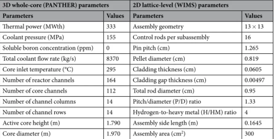
our previous studies9–12,17,22,30. Table 1 shows the 2D lattice-level (WIMS) and 3D whole-core (PANTHER) system
parameter values12,19,30–38. It is also important addressing that the results of this article have been introduced in the
PhD thesis19 of the corresponding author and also in a conference paper34.
Figure 1. Interconnectivity of the 2D lattice code WIMS and 3D whole-core code PANTHER for the proposed
Alterative and composite Burnable poison candidates
Our previous studies9–12,18,19 demonstrated that using localized, self-shielded gadolinia is an effective means of
moderate, long-term reactivity control. However, it has a number of drawbacks. Inherently, it reduces the ther-mal conductivity of the fuel, and it displaces fissile material, leading to reduced critical lifetime. Additionally, the heavy poison loadings required for long-life cores also lead to severe power peaking within the assembly. To avoid these shortcomings, we explored the feasibility of applying a layer of neutron poison to the outer surface of the fuel pellet in our previous studies9–12,18,19. The most prominent industrial implementation of this
strat-egy is Westinghouse’s IFBA. In a typical IFBA assembly, a very thin adhesive coating (1 mg/cm of pellet length ~590 nm thickness) of ZrB2 is sprayed onto the outer surface of a normal pellet. This offers important benefits
over traditional BP: 1. The poison is completely depleted, and hence there are no residual effects on reactivity at end of life (EOL); 2. ZrB2 is coated on the outside of an otherwise normal pin, so there is no change in fuel
conductivity, no displacement of fissile material, and no need for separate manufacturing/handling of poison pins. In our SBF marine core18, it required 25 absorber pins with 150 μm IFBA to suppress the initial reactivity
and the assembly power peaking at 1.29 is 18% higher than for Westinghouse civil IFBA assemblies (assembly PPF = 1.10). Unfortunately, in this thick-coating example, a higher PPF is seen due to the very strong neutron absorption effect. Therefore, in this study minimizing the core PPF will be an important goal. Furthermore, we have observed that “gray” absorbers (erbia) are best suited to trimming excess reactivity early in life (since they do not burn quickly) and “black absorbers” (gadolinia) are best used later in life (because of their lower burnup penalty). In this study, a composite BP is designed to take advantage of both erbia and IFBA, where the erbia provides extended reactivity control and the IFBA provides bulk reactivity suppression and longer cycle length. In addition, we will consider IFBA with gadolinia in order to observe the effect of a black absorber with the high coating BP. As addressed, in this study, all the IFBAs are high-thickness 150 μm IFBA.
In order to suppress excess reactivity and reduce the through-life reactivity swing, this BP study also pursues the novel technique of mixing Pu-240 homogeneously to the UO2 fuel39. The BOL reactivity can be suppressed
significantly by the addition of Pu-240 to the fuel. This is due to the fact that Pu-240 has significantly higher neutron capture cross section than that of the U-238 in the thermal energy range, as shown in Fig. 2. We will also investigate Am-241, which has capture cross section of ~800 barns at ~0.02 eV (Fig. 2) while the generation of Am-242m has excellent fissile properties40. Therefore, it is evident that Am-241 can be a potential candidate to
serve effectively as a BP for our SBF core40.
Finally, we investigate another composite BP: Pu-240 or Am-241 mixtures with high-thickness IFBA pins. Candidate BPs will be compared with the IFBA-only case for UO2 fuel. For the candidate BP cases, discharge
burnup was calculated at k∞=1 (neglecting leakage). These cases are shown in Fig. 3.
It is important addressing that Pu-240 is commercially available (e.g. from Oak Ridge National Laboratory) in very small quantities proportionate with commercial demand. The material itself is produced readily in commer-cial reactor fuel from which it can be separated via well-established reprocessing techniques. Internationally, the separation of plutonium from spent nuclear fuel has been undertaken extensively in the production of mixed oxide (MOX) fuel. Moreover, separation of Am-241 produced from the decay of Pu-241 in spent fuel is undertaken com-mercially for industrial applications (radioisotope source for instrumentation, e.g. gauges and smoke detectors). Several kilograms of Am-241 are produced per year, a quantity that could be scaled up if the commercial need was significant. Concerning non-proliferation, weapons-grade plutonium is deemed to have a below thresh-old quantity of Pu-240 as, because it has a similar cross-section to Pu-239 yet is not fissile, it competes for neu-trons and renders the Pu-239 useless for weapons manufacture. Pu-241 produced through the capture of neuneu-trons in Pu-240 is fissile, having a threefold higher cross-section than for neutron capture, Pu-241 is very radioactive, decaying to Am-241, and is hence too radioactive for use in weapons production. Recall that the Pu-241 will exist in the presence of Pu-240 and Am-241, all of which compete for neutrons, Am-241 is fissile yet has a 30-fold higher n-gamma cross-section so is not a significant risk. Obviously, all of these materials are nuclear materials and handled accordingly. It is anticipated that these burnable poisons be integrated during fuel production, like for MOX.
3D whole-core (PANTHER) parameters 2D lattice-level (WIMS) parameters
Parameters Values Parameters Values
Thermal power (MWth) 333 Assembly geometry 13 × 13
Coolant pressure (MPa) 155 Control rods per subassembly 16 Soluble boron concentration (ppm) 0 Pin pitch (cm) 1.265 Total coolant flow rate (kg/s) 8370 Pellet diameter (cm) 0.819 Core inlet temperature (°C) 295 Cladding thickness (cm) 0.0605 Number of reactor channels 164 Cladding gap thickness (cm) 0.00497 Number of core channels 112 Total rod diameter (cm) 0.95 Number of channel columns 14 Pitch/diameter (P/D) ratio 1.33 Number of channel rows 14 Hydrogen-to-heavy metal (H/HM) ratio 4 Active core height (m) 1.790 Assembly side length (m) 0.1645
Core diameter (m) 1.970 Assembly area (cm2) 300
investigation and Design of improved Burnable poisons
Case 1: 21 IFBA pins with gadolinia/erbia.
In this composite BP design, gadolinia (or erbia) and IFBA were used in the same lattice, however, in separate fuel rods. By precisely choosing the concentration and posi-tion of each BP, the assembly-level PPF is decreased. We have also examined the coexistence of Gadolinia/erbia and IFBA within the same fuel rod; however, the results were not promising. We observed that the external IFBA layer acted as a shielding by capturing neutrons. Therefore, depletion of gadolinia/erbia is delayed until the IFBA is fully consumed. This results in a greater residual burnup penalty, which necessarily shortens core life. Therefore, we have considered IFBA and gadolinia/erbia in separate fuel rods (Fig. 3(a)). Here we have considered high-thickness IFBA 150 μm pins and 10–30% Gd2O3 (Gd-IFBA) and Er2O3 (Er-IFBA).In this composite BP design, gadolinia (or erbia) and IFBA were used in the same lattice, however, in separate fuel rods. By precisely choosing the concentration and position of each BP, the assembly-level PPF is decreased. We have also examined the coexistence of Gadolinia/erbia and IFBA within the same fuel rod; however, the
Figure 2. Neutron capture cross sections (barns) of candidate burnable absorber nuclides.
Figure 3. Different BP candidates: (a) Case 1: Composite BP: gadolinia-IFBA or erbia-IFBA; (b) Case 2: Pu-240
results were not promising. We observed that the external IFBA layer acted as a shielding by capturing neutrons. Therefore, depletion of gadolinia/erbia is delayed until the IFBA is fully consumed. This results in a greater residual burnup penalty, which necessarily shortens core life. Therefore, we have considered IFBA and gadolinia/erbia in separate fuel rods (Fig. 3(a)). Here we have considered high-thickness IFBA 150 μm pins and 10–30% Gd2O3
(Gd-IFBA) and Er2O3 (Er-IFBA).
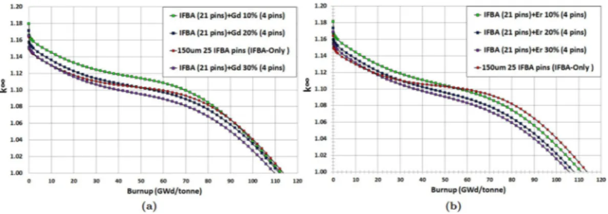
It can be observed from Fig. 4(a,b) that Gd-IFBA and Er-IFBA are promising BP designs for controlling reac-tivity swing later in life (compared to the IFBA-only BP) if higher concentrations (>10%) of Gd2O3 and Er2O3 are
employed. However, these designs cannot outperform the IFBA-only BP with regards to BOL reactivity suppres-sion since the crucial self-shielding effect is reduced due to the decrease in the IFBA-only pins.
The result shows that Gd-IFBA outperforms Er-IFBA concerning the performance of reactivity swing (Fig. 5(a)) and BOL reactivity suppression due to erbia’s much lower cross section compared to gadolinia. For this reason, erbia does not provide the same strong self-shielding41 and, therefore, suffers from larger EOL residual
burnup penalties compared to gadolinia (Fig. 5(b)), which inevitably shortens the discharge burnup and core life. We observed that if we increase Gd2O3 or Er2O3 concentration, we obtain a longer cycle at the expense of reduced
reactivity suppression. IFBA-only design is used as a reference, and in order to achieve the poisoning equivalent of the reference, Gd2O3 should be used. If using erbium is desired, then the poisoning mode must be altered because
it has a low absorption cross section. In addition, the erbium has to be highly diluted with a large number of rods. This results in a significant modification of the neutron 17 as a whole.
We conclude from our investigation of this BP strategy that use of the Gd-IFBA design can lead to a ~16% IFBA pins reduction while exhibiting the similar BP performance as for the IFBA-only design.
Case 2: Homogeneously mixed Pu-240 or Am-241 with UO
2fuel.
This study also pursues the novelidea of mixing Pu-240 or Am-241 homogeneously into the fuel39. Pu-240 is selected because of its high resonance
absorption (~105 barns) in the vicinity of ~1.04 eV in comparison with Pu-238 (~103 barns at ~2.85 eV), as shown
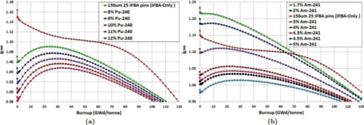
in Fig. 2. This results in Pu-240 being more efficient in suppressing excess reactivity. Figure 6(a,b) show that the homogeneous admixture of Pu-240 or Am-241 into the fuel substantially suppress BOL reactivity due to their much larger thermal capture cross sections than that of U-238 (1.73 barns). This allows the number of BP rods used for through-life reactivity swing and excess reactivity control to be reduced. Since the homogeneous mixture of Pu-240 or Am-241 homogeneously into the fuel regulates the self-shielding effect, BOL reactivity suppression is almost linearly proportional to the amount of Pu-240 or Am-241.
Homogeneous mixing of Pu-240 with UO2 gives promising results compared to the IFBA-only design. It can
be seen from Fig. 6(a) that homogeneous mixing of 8% Pu-240 reduces the reactivity swing by ~55% and exhibits ~9% more BOL reactivity suppression compared to the IFBA-only design while achieving a discharge burnup of ~100 GWd/tonne. A drawback is that it provides ~14 GWd/tonne reactivity penalty, which has a detrimental effect on core life. This suggests that reducing the amount of Pu-240 would lead to a smaller burnup penalty at the cost of less reactivity suppression and more swing.
Figure 4. k∞ vs. burnup for Case 1 BP candidates: (a) gadolinia-IFBA and (b) erbia-IFBA.
Am-241 mixed homogeneously with the fuel exhibits the same characteristics for the same reasons, although there are differences in the amounts of initial excess reactivity suppression, reactivity swing and burnup penalty. It can be seen from Fig. 6(b) that 3% Am-241 mixed with the fuel contributes to ~30% less reactivity swing and ~3% more suppression compared to the IFBA-only design while achieving a discharge burnup of ~100 GWd/ tonne, which clearly identifies a potential BP saving. An admixture of even relatively small amounts of Am-241 (e.g. 3% Am-241 concentration) strongly influences the local thermal flux and results in a marked depression of the local k , which ultimately influences the overall k∞ ∞ of the entire subassembly.
It is clear that Am-241 exhibits better BP performance than that of Pu-240 concerning the BOL reactivity suppression and reactivity swing (Fig. 7(a)), although Am-241 suffers from a larger EOL residual burnup penalty (Fig. 7(b)). This is due to the very slow burn-out of the Am-241 mixed fuel, which leads to a significant residual absorption penalty. Utilizing higher initial enrichment might be a solution to avoid this problem. The amount of reactivity suppressed at BOL increases with the addition of Pu-240 or Am-241 compared to the IFBA-only design. Therefore, the BP requirements can be reduced by using Pu-240 or Am-241 mixed homogeneously with the fuel.
Case 3: 21 IFBA pins with homogeneously mixed Pu-240 or Am-241 with UO
2fuel.
Finally, wehave observed promising results for the IFBA-Pu-240 (IFBA-Pu) and IFBA-Am-241 (IFBA-Am) configurations (Case 3). In this strategy, 21 IFBA pins were used and Pu-240 or Am-241 were mixed homogeneously with the fuel. It can be seen from Fig. 8(a) that the IFBA-Pu configuration with 3% Pu-240 results in a ~60% lower reactivity swing and ~8% more reactivity suppression compared to the IFBA-only design while providing almost the same cycle length. Another promising configuration is the IFBA-Am mixture (Fig. 8(b)) with 2% Am-241, which offers better reactivity swing and suppression performance but with ~2 GWd/tonne less cycle length than the IFBA-Pu configuration.
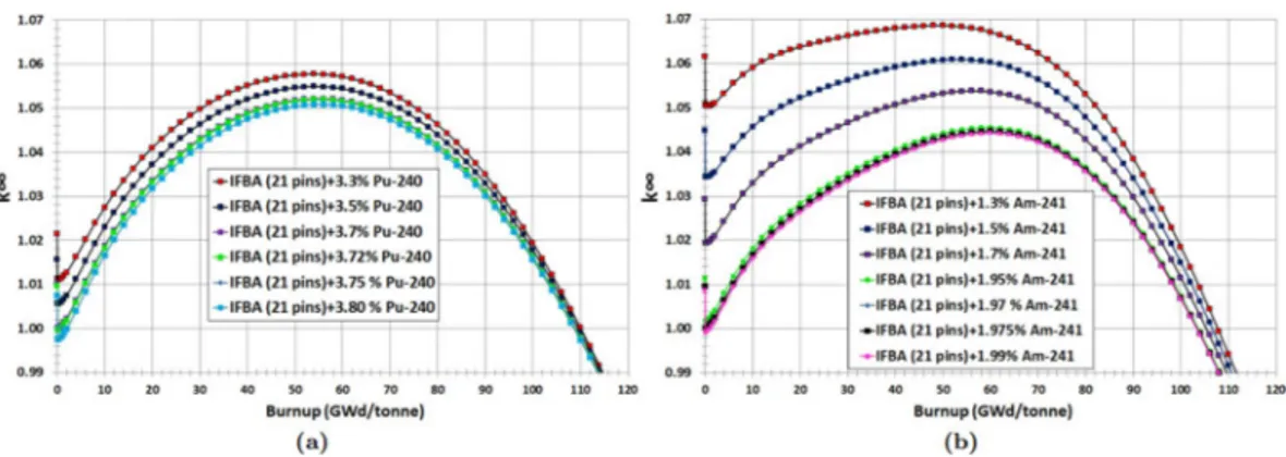
We can conclude from this study that composite BPs such as the IFBA-Pu and IFBA-Am designs are better BP designs than the IFBA-only design in terms of reactivity swing and suppression while providing comparable cycle lengths. However, these Case 3 BP designs require further optimization in order to achieve the minimum possible BOL k and reactivity swing while maintaining a discharge burnup of ≥100 GWd/tonne. Figure ∞ 9(a,b) show that
IFBA-Pu with 3.70% Pu-240 and IFBA-Am with 1.975% Am-241 can provide ~70% reduced swing and ~10% more reactivity suppression compared to the IFBA-only design while yielding cycle lengths of ≥100 GWd/tonne.
IFBA-Pu and IFBA-Am designs exhibit better BP performance compared to the previously considered cases (Cases 1 and 2). This is due to the fact that an IFBA 150 μm absorbs ~95% of incident neutrons since this poison layer consists of a thickness of 3λ, where λ is the neutron mean free path. This leads to the severely attenuated neutron flux in fuel pin early in life. However, later in life, fuel pin gradually experiences power as the BP burns off. As expected, late in life, higher fissile content will be present in the BP-coated fuel pins, allowing the assembly to stay critical even longer than if it had no poison at all. With this (Case 3) BP configuration, minimum reactivity
Figure 6. k∞ vs. burnup for for Case 2 BP candidates: (a) homogeneously mixed Pu-240 with UO2 fuel; (b)
homogeneously mixed Am-241 with UO2 fuel.
swing and higher BOL reactivity suppression compared to Cases 1 and 2 can be obtained while achieving a dis-charge burnup of ~100 GWd/tonne (Fig. 10).
This design study suggests that the Case 3 (IFBA-Pu and IFBA-Am) designs are to be preferred for our SBF marine core application. BP designs using 21 IFBA pins with homogeneously mixed 3.70% Pu-240 (IFBA-Pu) or 1.975% Am-241 (IFBA-Am) will therefore be used in our whole-core analyses.
power peaking factors
BOL subassembly-level PPFs for one octant assemblies have been considered for Cases 1–3. It can be observed for the Case 1 alternative BPs that UO2 assemblies exhibit PPF of 1.35 and 1.34 with 30% gadolinia-IFBA (Fig. 11(b)) and 30%
erbia-IFBA (Fig. 11(c)) respectively, which are ~6% higher than the IFBA-only BP with 25 absorber pins (PPF of 1.28). Furthermore, Case 2 alternative BPs exhibit excellent improvement in PPF values of 1.153 and 1.152 with 8%
240Pu (Fig. 12(a)) and 3% 241Am (Fig. 12(b)) respectively, which are ~10% lower than the IFBA-only BP with 25
absorber pins. Case 2 alternative BPs show improvements in controlling PPF, although these exhibit significant discharge burnup penalty.
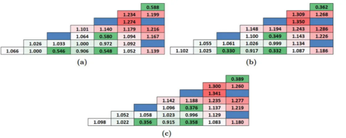
In addition, It can also be observed in Fig. 13 for Case 3 that UO2 assemblies exhibit PPF of 1.29 and 1.26 with
IFBA-Pu (3.70% Pu-240) and IFBA-Am (1.975% Am-241), respectively. It is important noting that addressing that non-IFBA options (Case 2) exhibit the lowest PPF, while IFBA-Pu and IFBA-Am (Case 3) exhibit comparable PPF values to IFBA-only case.
Whole-core feasibility
In Section 4.3, we developed a subassembly design with BPs that was optimized for controlling reactivity swing for obtaining target core lifetime of 15 years. In the previous phase of the assembly-level BP studies, WIMS per-forms deterministic neutron transport calculations for every pin in a fuel assembly; however, it does these calcula-tions for an infinitely large core, neglecting the finite height and radius of an actual reactor. Hence, WIMS cannot describe the effects of neutron leakage. To explore these essential aspects of whole-core reactor design, we use the whole-core code PANTHER by loading these assemblies. The main objectives of this whole-core feasibility analyses are to confirm the criteria below while reducing 20% IFBA use:
1. To confirm that the subassembly design with the alternative BP has sufficient reactivity for the desired 15-year operation period.
2. To ensure the lowest possible through-life reactivity swing (below 4000 pcm) in order to reduce the de-pendency on control rods.
Figure 8. k∞ vs. burnup for Case 3 BP candidates: (a) IFBA-Pu; (b) IFBA-Am.
Figure 9. k∞ vs. burnup for Case 3 BP candidates: (a) Optimization of Pu-240 content of composite BP
3. To maintain whole-core radial form factor (RFF) below the industrial limit of 1.50 over life to prevent spatial power-peaking.
4. To evaluate the key neutronic safety parameters to confirm that the reactivity feedback (fuel and modera-tor temperature coefficient) are negative and axial offset (AO) values are within the acceptable range from −10% to +10%.
Figure 10. Comparison of different BP candidate design cases.
Figure 11. BOL pin power distribution of one octant assembly: (a) 150 μm 25 IFBA pins; (b) Gadolinia-IFBA
(30% gadolinia with 4 pins–IFBA with 21 pins); (c) Erbia-IFBA (30% erbia with 4 pins–IFBA with 21 pins).
Figure 12. BOL pin power distribution of one octant assembly for homogeneously mixed actinides with UO2
fuel: (a) 8% 240Pu; (b) 3% 241Am.
Figure 13. BOL pin power distribution of one octant assembly: (a) IFBA-Pu (3.70% Pu-240); (b) IFBA-Am
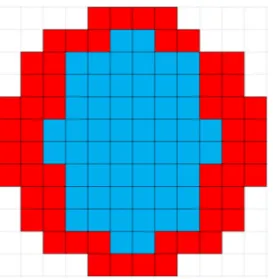
This whole-core study models the 112-subassembly core10 using PANTHER and divide it into two radial
zones (A and B, see Fig. 14) while considering the hot full power operating conditions (fuel temperature = 900 K, coolant temperature = 580 K and coolant density = 707 kg/m3) and all control rods out conditions. We consider a
radial-zoning loading pattern (LP) scheme in which assemblies in Zones A and B have IFBA-Pu or IFBA-Am and IFBA-only assemblies, respectively. Since we observed in Sect.4.3 that Case 3: 3.70% Pu-240 (IFBA-Pu) or 1.975% Am-241 (IFBA-Am) assemblies exhibit a burnup penalty compared to the IFBA-only assembly, 50% (56) of the locations are loaded with IFBA-only assemblies in order not to compromise the desired core lifetime of 15 years. Comparisons are made with the full core loaded entirely with IFBA-only assemblies.
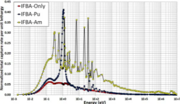
It can be seen in Fig. 15 that both the IFBA-Pu and IFBA-Am cores are successful in achieving the target core lifetime of 15 years for the proposed SBF SMR core. The IFBA-Pu core can achieve a ~6% (272 days) longer core life than the IFBA-Am core. Both the IFBA-Pu and IFBA-Am cores exhibit a shorter core lifetime than the IFBA-only core due to the residual burnup penalty associated with their corresponding BP designs. On the other hand, the IFBA-Pu and IFBA-Am cores exhibit ~10% higher BOL reactivity suppression and ~70% lower reactiv-ity swings (below the targeted 4000 pcm) than the IFBA-only core while reducing 20% IFBA use, the former due to their much higher capture rates per unit lethargy over the thermal energy range below 1 eV (Fig. 16).
Figure 17(a) shows the variation of the radial form factor (RFF) over the core lifetime for the SMR cores. IFBA-only core experiences a maximum RFF of ~1.9 at the BOL due to the very high power share in inner subassemblies10. In contrast, IFBA-Pu and/or IFBA-Am can maintain the through-life RFF values below 1.50.
Figure 17(b,c) show the variation of the axial form factor (AFF) and total form factor (FQ), respectively. The values of AFF and FQ should not exceed 1.60 and 2.52, respectively, at hot full power10,39. It can be seen that both the IFBA-Pu and IFBA-Am cores can maintain the through-life AFF and FQ values below their allowable limits, while the IFBA-only core exceeds these limits. It is worthwhile addressing that IFBA-Pu and IFBA-Am cores can achieve ~30% lower RFF and ~28% lower FQ compared to the IFBA-only core.
The axial offset (AO) is the ratio of the normalized power difference between the top and bottom halves of the core. This is a measure of the axial imbalance of power generation and is sought to be minimised to control the AFF. The recommended AO values should be in the range of −10% to +10%10,39. Figure 18 indicates that
IFBA-only, IFBA-Pu and IFBA-Am perform reasonably favourably according to this measure while experiencing
Figure 14. Radial zoning whole-core loading pattern in the 112-assembly SMR core: blue = A (56 assemblies),
red = B (56 assemblies). Blue denotes IFBA-Pu or IFBA-Am assemblies and red denotes IFBA-only assemblies.
the through-life AO values from ~−4.5% to ~+3% but this is the result of a complex coupling of neutronics and thermal-hydraulic feedback. It is also observed that due to the higher AFF experienced by the IFBA-Pu core early in life, its AO is slightly higher than that of the IFBA-Am core for the first 6 years. Later in life, the IFBA-Am core exhibits a higher AO due to its higher AFF. Hence, it is concluded that this AO characteristic is coherent with the AFF values. The higher burnup in the lower portion of the fuel assembly later in life, leading to the depletion of fissile nuclei in this region, is the cause of the swing toward a positive AO for all the cores. However, average AO values are negative due to the efficient moderation and higher fissile concentration in the bottom of the cores10.
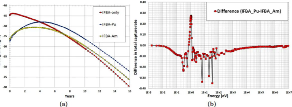
Two important reactivity feedback parameters: moderator temperature coefficient (MTC) and fuel tempera-ture coefficient (FTC) are evaluated in the whole-core feasibility study. The MTC is an indication of the intrinsic stability of the reactor to coolant temperature, and therefore power, transients. The more negative this parameter is, the more quickly the reactor will tend to stabilise itself if the coolant temperature rises due to a peak in power. Figure 19(a) illustrates the strong negative MTC over core life since no soluble boron is used in the proposed SMR core. IFBA-Pu core exhibits marginally more negative MTC value than the IFBA-Am core at BOL due to the large resonances in the vicinity of ~1.1 eV (Fig. 16)10,41. Figure 19(b) shows the difference in total neutron capture
rate between that IFBA-Pu and that IFBA-Am core. It can be observed that IFBA-Pu core exhibits a higher total neutron capture rate than that of the IFBA-Am core in the vicinity of ~1.1 eV10.
Figure 20(a) confirms that FTC values are negative throughout the core lifetime for the candidate SMR cores and IFBA-Pu core shows considerably more negative FTC values than that of the IFBA-Am core. Figure 20(b) shows the difference in fertile capture rate between that IFBA-Pu and that IFBA-Am core. It can be observed that IFBA-Pu core exhibits higher fertile capture rate than that of the IFBA-Am core in the vicinity of ~6.8 eV10.
conclusions
This study focused on the design and neutronic performances of alternative BP loading schemes to reduce the use of 150 μm IFBA in the proposed soluble-boron-free SMR core since B-10 in IFBA undergoes an (n, α) capture reaction, and the resulting helium raises the pressure within the plenum and in the cladding. This paper consid-ered three novel types and strategies of BP loading scheme: (Case 1) a composite BP: gadolinia (Gd2O3) or erbia
(Er2O3) with 150 μm thickness ZrB2 IFBA; (Case 2) Pu-240 or Am-241 mixed homogeneously with the fuel;
(Case 3) another composite BP: Pu-240 or Am-241 with 150 μm thickness ZrB2 IFBA. All the BP candidates were
compared with the reference high-thickness IFBA-only (150 μm 25 IFBA pins) BP design for UO2 fuel. The key
findings of this neutronic study are:
1. Case 1 (21 IFBA Pins with 4 gadolinia/erbia pins): Gd-IFBA outperforms Er-IFBA concerning the per-formance of reactivity swing and BOL reactivity suppression. The use of the Gd-IFBA design can lead to a ~16% IFBA pins reduction while exhibiting the similar BP performance as for the IFBA-only design. 2. Case 2 (Homogeneously mixed Am-241/Pu-240): Am-241 exhibits better BP performance than that of
Pu-240 concerning the BOL reactivity suppression and reactivity swing, although Am-241 suffers from a larger EOL residual burnup penalty.
3. Case 3 (21 IFBA pins with homogeneously mixed Pu-240 or Am-241): IFBA-Pu (3.70% Pu-240) and IFBA-Am (1.975% Am-241) designs are better BP designs than the IFBA-only design in terms of reac-tivity swing and suppression while providing comparable cycle lengths. IFBA-Pu with 3.70% Pu-240 and IFBA-Am with 1.975% Am-241 can provide ~70% reduced swing and ~10% more reactivity suppression compared to the IFBA-only design while yielding cycle lengths of ≥100 GWd/tonne. This design study suggested that the Case 3 (IFBA-Pu and IFBA-Am) designs are to be preferred for our SBF marine core application.
4. Non-IFBA options exhibit the lowest PPF, while IFBA-Pu and IFBA-Am (Case 3) exhibit comparable PPF values to IFBA-only case.
Figure 18. Axial offset (%) as a function of time (years) for the radial-zoning core LP.
Figure 19. (a) MTC as a function of time (years) for the radial-zoning core LP; (b) Difference in total BOL
5. In the whole-core study, Case 3 BPs (IFBA-Pu and IFBA-Am cores) are successful in achieving the target core lifetime of 15 years for the proposed SBF SMR core. The IFBA-Pu core can achieve a ~6% (272 days) longer core life than the IFBA-Am core. Case 3 BPs contributes to ~10% higher BOL reactivity suppres-sion, ~70% lower reactivity swings ~30% lower radial form factor and ~28% lower total peaking factor compared to the IFBA-only core while reducing 20% IFBA use for reactivity control.
It can be concluded from this design study that the proposed composite BPs using Pu-240 and Am-241 with IFBA (IFBA-Pu and IFBA-Am) are the preferred burnable poison option for a SBF and long life SMR marine core since these admixtures result in larger initial excess reactivity suppression, reduced reactivity swing, lower power peaking factors and, thus, higher potential BP savings compared to the IFBA-only design while reducing 20% IFBA use. The higher BOL reactivity suppression and smaller reactivity swing of IFBA-Pu and IFBA-Am make the task of reactivity control in a long life SBF core easier than that of the traditional burnable poisons. These composite BPs exhibit a small residual burnup penalty at EOL compared to the IFBA-only design.
The scope of this paper is only limited to the neutronic feasibility of candidate BPs. Future work will also con-sider the neutronic and practical implications (availability of the fuel, problems of separation and manufacture) and proliferation concerns of these proposed BPs.
Received: 29 November 2018; Accepted: 26 October 2019; Published: xx xx xxxx
References
1. Hirdaris, S. et al. Considerations on the potential use of nuclear small modular reactor (SMR) technology for merchant marine propulsion. Ocean Eng. 79, 101–130 (2014).
2. Ragheb, M. Nuclear marine propulsion. University of Illinois at Urbana-Champaign (2012).
3. Khlopkin, N. & Zotov, A. Merchant marine nuclear-powered vessels. Nucl. Eng. Des. 173, 201–205 (1997).
4. Vergara, J. A. & McKesson, C. B. Nuclear propulsion in high-performance cargo vessels. Mar. Technol. 39, 1–11 (2002).
5. Ragheb, M. Nuclear naval propulsion. In Tsvetkov, P. (ed.) Nuclear Power – Deployment, Operation and Sustainability, chap. 1, 3–32 (InTech, Rijeka, Croatia, 2011).
6. Otto, R. T. Core Optimization in a Thorium-based Civil Marine Propulsion Reactor. Master’s thesis, Department of Engineering, University of Cambridge (2013).
7. Namikawa, S., Mærli, M., Hoffmann, P. & Brodin, E. Nuclear powered ships – findings from a feasibility study. In Proc. 19th Int.
Conf. Nuclear Engineering (ICONE19) (Chiba, Japan, 2011).
8. Kramer, A. Nuclear Propulsion for Merchant Ships. (US Atomic Energy Commission, Washington, DC, 1962).
9. Alam, S. B. et al. Small modular reactor core design for civil marine propulsion using micro-heterogeneous duplex fuel. Part I: Assembly-level analysis. Nucl Eng Des. 346, 157–175 (2019).
10. Alam, S. B. et al. Small modular reactor core design for civil marine propulsion using micro-heterogeneous duplex fuel. Part II: Whole-core analysis. Nucl Eng Des. 346, 176–191 (2019).
11. Alam, S. B., de Oliveira, R. G., Goodwin, C. S. & Parks, G. T. Coupled neutronic/thermal-hydraulic hot channel analysis of high power density civil marine SMR cores. Annals of Nuclear Energy 127, 400–411 (2019).
12. Alam, S. B., Goodwin, C. S. & Parks, G. T. Parametric neutronics analyses of lattice geometry and coolant candidates for a soluble-boron-free civil marine SMR core using micro-heterogeneous duplex fuel. Annals of Nuclear Energy 129, 1–12 (2019).
13. Nguyen, X. H., Kim, C. & Kim, Y. An advanced core design for a soluble-boron-free small modular reactor ATOM with centrally-shielded burnable absorber. Nuclear Engineering and Technology 51, 369–376 (2019).
14. Yahya, M.-S. & Kim, Y. An innovative core design for a soluble-boron-free small pressurized water reactor. International Journal of
Energy Research 42, 73–81 (2018).
15. Almutairi, B. et al. Reactor physics analysis of thorium-based fuel for long-life SMR cores using seed-blanket fuel concept.
Transactions of the American Nuclear Society 120, 875–878 (2019).
16. Alam, S. B., Almutairi, B., Ridwan, T., Kumar, D. & Goodwin, C. Uncertainty quantification of smr core linear power using polynomial chaos method. Transactions of the American Nuclear Society 120, 867–870 (2019).
17. Alam, S. B., Goodwin, C. S. & Parks, G. T. Assembly-level analyses of accident-tolerant cladding concepts for a long-life civil marine SMR core using micro-heterogeneous duplex fuel. Prog Nucl Energ 111, 24–41 (2019).
18. Alam, S. B., Lindley, B. A. & Parks, G. T. Feasibility study of the design of homogeneously mixed thorium-uranium oxide and all-uranium fueled reactor cores for civil nuclear marine propulsion. In Proc. ICAPP 2015, 1918–1927 (Nice, France, 2015). 19. Alam, S. B. The Design of Reactor Cores for Civil Nuclear Marine Propulsion. Ph.D. thesis, University of Cambridge (2018).
Figure 20. (a) As a function of time (years) for the radial-zoning core LP; (b) Difference in fertile capture rate
20. Newton, T. et al. Developments within WIMS10. In Proc. PHYSOR 2008 (Interlaken, Switzerland, 2008).
21. Lindley, B. et al. Current status of the reactor physics code WIMS and recent developments. Annals of Nuclear Energy 102, 148–157 (2017). 22. Alam, S. B. et al. Lattice benchmarking of deterministic, Monte Carlo and hybrid Monte Carlo reactor physics codes for the
soluble-boron-free SMR cores. Nucl Eng Des. (2019).
23. Alam, S. B., Almutairi, B., Kumar, D., Goodwin, C. S. & Alameri, S. A. Convergence studies using method of characteristics solver for the reduced-moderation water reactor model. In Proc. Pacific Basin Nuclear Conference, 119–128 (San Francisco, CA, USA, 2018). 24. Alam, S. B., Almutairi, B., Kumar, D., Goodwin, C. S. & Alameri, S. A. 3D modeling of reduced-moderation water reactor lattice for
P0 and P1 scattering approximations using deterministic and monte carlo codes 285–294 (2018).
25. Zainuddin, N. Z. In-core Optimisation of Thorium-Plutonium-fuelled PWR Cores. Ph.D. thesis, University of Cambridge (2015). 26. Newton, T. WIMS: A Modular Scheme for Neutronic Calculations–User Guide for Version 10 (ANSWERS/WIMS(08)9, The
ANSWERS Software Service, 2009).
27. Hutt, P. Overview Functional Specification of PANTHER: A Comprehensive Thermal Reactor Code for Use in Design, Assessment and
Operation. (PANTHER/FSPEC/OVERVIEW 2.0, Nuclear Electric plc, Barnwood, UK, 1992).
28. Zhang, J. Commercial Nuclear Marine Reactor Physics Design for Uranium Fuel. Master’s thesis, Department of Engineering, University of Cambridge, Cambridge, UK (2013).
29. Fan, H. The Conceptual Design of a Marine Propulsion Reactor Core. Master’s thesis, Department of Engineering, University of Cambridge, Cambridge, UK (2012).
30. Alam, S. B. et al. Neutronic feasibility of civil marine small modular reactor core using mixed D2O+H2O coolant. Nucl Eng Des. (2020). 31. Alam, S. B., Lindley, B. A. & Parks, G. T. Hot channel analysis of a 333 MWth civil nuclear marine core using the COBRA-EN code. In Proc. 16th International Topical Meeting on Nuclear Reactor Thermal Hydraulics (NURETH-16), 5900–5913 (Chicago, Illinois, USA, 2016).
32. Alam, S. B., Lindley, B. A. & Parks, G. T. Neutronic performance of high power density marine propulsion cores using UO2 and microheterogeneous ThO2-UO2 duplex fuels. In Proc. PHYSOR 2016, 3519–3531 (Sun Valley, Idaho, USA, 2016).
33. Alam, S. B., Parks, G. T. & Lindley, B. A. Hot assembly and whole-core thermal-hydraulic analysis of a high power density marine core with neutronic/thermal-hydraulic coupling. In Proc. PHYSOR 2016, 3506–3518 (Sun Valley, Idaho, USA, 2016).
34. Alam, S. B., Lindley, B. A., Parks, G. T. & Shwageraus, E. Burnable poison designs for a soluble-boron-free civil nuclear marine PWR core. In Proc. PHYSOR 2016, 1926–1938 (Sun Valley, Idaho, USA, 2016).
35. Alam, S. B., Mohamed, H., Lindley, B. A. & Parks, G. T. Analysis and design of a high power density marine PWR core using mixed D2O-H2O coolant and checkerboard micro-heterogeneous ThO2-UO2 and all-uranium fuel. In Proc. ICAPP 2016, 1678–1686 (San Francisco, California, USA, 2016).
36. Alam, S. B., Mohamed, H., Lindley, B. A. & Parks, G. T. Lattice design and coolant selection for a 333 MWth PWR civil marine propulsion core using checkerboard micro-heterogeneous ThO2-UO2 fuel. In Proc. ICAPP 2016, 1687–1696 (San Francisco, California, USA, 2016).
37. Alam, S. B., Oliviera, R. D., Parks, G. T. & Shwageraus, E. Hot channel analysis of a 333 MWth high power density civil marine core using 3D neutronic/thermal-hydraulic coupling of hybrid monte carlo MONK with sub-channel analysis COBRA-EN code. In Proc.
ICAPP 2017, 17331–17340 (Fukui and Kyoto, Japan, 2017).
38. Alam, S. B., Goodwin, C. & Parks, G. T. Reactor physics assessment of candidate accident-tolerant cladding concepts for long-life civil nuclear marine propulsion cores. In Proc. ICAPP 2017, 17309–17318 (Fukui and Kyoto, Japan, 2017).
39. Kim, S. Y. & Kim, J. K. A reactivity hold-down strategy for soluble boron free operation by introducing Pu-238 added fuel. Ann.
Nucl. Energy 27, 855–871 (2000).
40. Ronen, Y., Golyand, L. & Shwageraus, E. The potential use of 241Am as proliferation resistant burnable poison in PWRs. Annals of
Nuclear Energy 37, 201–207 (2010).
41. Franceschini, F. & Petrović, B. Fuel with advanced burnable absorbers design for the IRIS reactor core: Combined erbia and IFBA.
Ann. Nucl. Energy 36, 1201–1207 (2009).
42. Zainuddin, N. Z. & Lindley, B. A. Notes on WIMS, WIMSbuilder and PANTHER. (University of Cambridge, Cambridge, UK, 2014).
Author contributions
S.B. Alam performed this design analyses, coded in software and wrote the paper. G.T. Parks, C.S. Goodwin and Kirk D. Atkinson provided feedback/corrections on technical stuff. T. Ridwan, D. Kumar and B. Alumtairi helped in revision and writing the final version of this paper.
competing interests
(1) Some portions of the article are published in the Ph.D. thesis and a conference paper of the first author. (2) The first author was a Doctoral Researcher at the University of Cambridge where this study has been conducted using the local repository and in-house licensed reactor physics codes WIMS and PANTHER. This is not the current affiliation of the first author. Since this work has been conducted at the first author’s Ph.D. institution (University of Cambridge) using the licensed codes and local repository, it is included as the affiliation to showcase where this work has been originally performed.
Additional information
Correspondence and requests for materials should be addressed to S.B.A. Reprints and permissions information is available at www.nature.com/reprints.
Publisher’s note Springer Nature remains neutral with regard to jurisdictional claims in published maps and
institutional affiliations.
Open Access This article is licensed under a Creative Commons Attribution 4.0 International
License, which permits use, sharing, adaptation, distribution and reproduction in any medium or format, as long as you give appropriate credit to the original author(s) and the source, provide a link to the Cre-ative Commons license, and indicate if changes were made. The images or other third party material in this article are included in the article’s Creative Commons license, unless indicated otherwise in a credit line to the material. If material is not included in the article’s Creative Commons license and your intended use is not per-mitted by statutory regulation or exceeds the perper-mitted use, you will need to obtain permission directly from the copyright holder. To view a copy of this license, visit http://creativecommons.org/licenses/by/4.0/.