58
ISBN: 978-91-88898-64-7
Strength and fracture analysis of shear mode III in cross laminated timber
Henrik Danielsson†*, Erik Serrano†, and Per Johan Gustafsson†
†Division of Structural Mechanics, Lund University, henrik.danielsson@construction.lth.se,
erik.serrano@construction.lth.se, per-johan.gustafsson@construction.lth.se
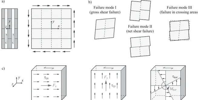
At in-plane shear loading of cross laminated timber (CLT), three failure modes (FM) are generally considered in design: gross shear failure (FM I), net shear failure (FM II) and shear failure in the crossing areas (FM III). FM III relates to shear stresses acting in the crossing areas between flat-wise bonded laminations, belonging to adjacent layers and being oriented orthogonally to one another. Relative translations and relative rotation between the two bonded laminations give rise to shear stresses acting in the plane of the bonded area, i.e. the xy-plane according to Figure 1.
For design with respect to FM III, considering relative translation and rotation, the following stress interaction failure criteria have been proposed in e.g. [1] and [2]
, , 1.0 and , , 1.0 (1a), (1b)
where τtor is a torsional shear stress due to the torsional moment Mtor while τzx and τzy are the shear stresses due to shear forces Fx and Fy, respectively, see Figure 1. The torsional shear stress τtor is assumed to be equal to the maximum shear stress at the mid-points of the edges of the crossing area, as calculated from linear elastic theory using the polar moment of inertia of the bonded area. The corresponding shear strength, fv,tor, refers to the strength at pure torsional loading. Shear stress components τzx and τzy are in design commonly assumed to be uniformly distributed and the corresponding strength value, fv,R, refers to the rolling shear strength of the laminations.
Figure 1: Illustration of a) cross laminated timber at in-plane shear loading b) corresponding shear failure modes I, II and III and c) decomposition of shear stress components τzx, τzy and τtor and their assumed distributions within a crossing area. 3D non-linear finite element (FE) analyses have been performed in order to investigate the strength and fracture course for shear failure mode III, as proposed in [3]. A single node, consisting of two orthogonally bonded laminations, was modelled. The bonding between the laminations was modelled using a cohesive zone approach, including strain softening behaviour after reaching the local material strength. Loading conditions representing pure shear force, pure torsion and mixed modes were considered and the global load-bearing capacity and the fracture course was studied. The presentation discusses the results of the FE-analyses in relation to experimental test results, considering the failure criteria in Equations (1a) and (1b).
References
[1] M. Flaig: Biegeträger aus Brettsperrholz bei Beanspruch in Plattebene. PhD thesis, KIT, Karlsruhe, Germany, 2013. [2] M. Flaig, H.J. Blass: Shear strength and shear stiffness of CLT-beams loaded in plane. In: Proc. CIB-W18,
CIB-W18/46-12-3, Vancouver, Canada, 2013.
[3] E. Serrano: Test methods for in-plane shear tests of cross laminated timber. In: Properties, testing and design of cross laminated timber: A state-of-the-art report by COST Action FP1402/WG2, Shaker Verlag, Aachen, Germany, 2018.
y x y z τzx τzy τtor Failure mode I
(gross shear failure)
Failure mode II (net shear failure)
Failure mode III (failure in crossing areas)
a) b) c) y x z Fy Fx Mtor