On the Solidification of Compacted
and Spheroidal Graphite Irons
Björn Domeij
Department of Materials and Manufacturing
SCHOOL OF ENGINEERING, JÖNKÖPING UNIVERSITY Jönköping, Sweden 2017
Licentiate Thesis
On the solidification of compacted and spheroidal graphite irons
Björn Domeij Department of Materials and Manufacturing School of Engineering, Jönköping University SE‐551 11 Jönköping, Sweden Bjorn.Domeij@ju.se Copyright © Björn Domeij Research Series from the School of Engineering, Jönköping University Department of Materials and Manufacturing Dissertation Series No. 24, 2017 ISBN: 978‐91‐87289‐25‐5 Published and Distributed by School of Engineering, Jönköping University Department of Materials and Manufacturing SE‐551 11 Jönköping, Sweden Printed in Sweden by Ineko AB Kållered, 2017i
ABSTRACT
A good understanding of the solidification process of a cast material is essential to understand how the combination of alloy composition and the casting process variables combines into the solid cast component and its performance. The wrong combination may result in poor performance or casting defects. Spheroidal graphite has been well researched in ductile irons (SGI) where it is predominant. Spheroidal graphite is also present in smaller amounts in compacted graphite irons (CGI), but its nature and role in this material is less understood. Recent associations of spheroidal graphite in CGI with shrinkage porosity problems highlights the need for better understanding in this area. The importance of the dendritic austenite structure to the properties and solidification behaviour of cast irons has been highlighted in recent research. However, progress is to a degree limited by lack of practical means to characterize the structure.In the present work, the transition of a cast iron from SGI to CGI though remelting was studied. As the fraction of SG dropped, the tips of the compacted graphite tended to lose contact with the melt at a later stage. After this occurred, solidification appeared to be dominated by spheroidal graphite. Compacted and spheroidal graphite was found to solidify mostly segregated, and the increased recallescence induced by a higher fraction of compacted graphite displayed small influence on the size distribution of spheroidal graphite apart from the total number and fraction. The partitioning of Si, Mn and Cu in SGI and CGI was found to agree well with each other, as well as with theoretical predictions under the assumptions of zero diffusion of the elements in the solid. This shows that the proportions of spheroidal and compacted graphite has small or no influence on the evolution of these elements in the melt during solidification. A method for characterization of the dendritic austenite in quenched cast irons was introduced and evaluated. The method includes a technique for producing a visual contrast between the ledeburite matrix and the dendritic austenite, and a scheme for producing binary images from the resulting micrographs which are suitable for automatic image analysis. Measurements of the volume fraction and surface area per unit volume of the dendritic austenite structure using the introduced method was found to agree reasonably with traditional point counting and line intercept techniques. The difficulty in finding the exact boundary was proposed to be the major source of systematic disagreement.
Keywords: Compacted graphite iron, Spheroidal graphite iron, Solidification,
ii
iii
SAMMANFATTNING
En god förståelse för stelningsprocessen av ett gjutet material är väsentligt för att förstå hur kombinationen av legeringens kemiska sammansättning och gjutprocessens variabler resulterar i den stelnade komponenten och dess prestanda. Fel kombination kan resultera i sänkt prestanda eller gjutdefekter. Sfärisk grafit är väl studerad i segjärn (SGI) där grafitmorfologin är dominant. Mindre mängder sfärisk grafit är dock närvarande även i kompaktgrafit, där dess karaktär och roll är mindre känd. Samband mellan sfärisk grafit i kompaktgrafitjärn och krympporositet understryker behovet av bättre förståelse inom detta område. Dessutom har betydelsen av den tidiga dendritiska austenitstrukturen för senare delen av stelningen uppmärksammats. Utveckling inom detta område är dessvärre till en grad begränsad av bristen på kunskap om praktiska metoder för att karaktärisera dess struktur.I detta arbete studerades övergången från segjärn till kompaktgrafit genom omsmältning. Vid sänkt fraktion sfärisk grafit visade sig kompaktgrafiten tappa kontakten med smältan vid senare stadie av stelningen. Efter detta inträffade, dominerades stelningen till synes av tillväxt av sfärisk grafit. Kompaktgrafit och sfärisk grafit bildades i huvudsak segregerade. Ökad rekallesens till följd av ökad fraktion kompaktgrafit visade sig ha låg inverkan på storleksfördelningen av eutektisk sfärisk grafit bortsett från dess totala antal och fraktion. Omfördelningen av Si, Mn och Cu mellan stelnad matris och smälta i segjärn och kompaktgrafitjärn fanns stämma bra överens med varandra, samt med teoretiska värden med antagande om försumbar diffusion i stelnad matris. Detta visar att proportionerna av sfärisk och kompaktgrafit har liten eller ingen inverkan på halten av dessa ämnen i smältan under stelningen. En metod för karaktärisering av den dendritiska austenitstrukturen i släckt gjutjärn introducerades och utvärderades. Metoden inkluderar en teknik för att åstadkomma kontrast mellan ledeburitmatrisen och den dendritiska austeniten, och en teknik för att producera binära bilder från resulterande mikroskopbilder som är lämpliga för automatisk bildanalys. Mätningar av volymfraktion och yta per volymenhet av dendritstrukturen genom tillämpning av den introducerade metoden visade rimlig överensstämmelse med traditionella punktfraktion‐ och linjetekniker. Svårigheten att hitta den exakta gränslinjen mellan dendritisk struktur och ledeburit föreslogs vara den huvudsakliga källan till systematisk oöverensstämmelse.
iv
v
ACKNOWLEDGEMENTS
I express my sincere gratitude to:My supervisor Attila Diószegi, for giving me this opportunity and for being a constant source of inspiration, guidance and support.
Juan Carlos Hernando, for his friendship and valued advices and discussions. Kaj Grönlund and Gunilla Runnsjö for their inspiring work, enthusiasm and
interesting discussions. Lucian Vasile Diaconu for his support and help. Jörgen Bloom for his help in casting activities and various practical issues. Esbjörn Ollas for his work on the experimental equipment. Peter Gunnarson and Lars Johansson for help in the workshop. Jessica Elfsberg for her excellent project leadership. All my colleagues at the department of materials and manufacturing. To my family for their love and support during this work. All participants of the Spofic II project and the involved industrial partners Scania CV AB, Volvo Group AB, Swerea SWECAST, for their valuable contribution to the work, and to Vinnova for the financial support of the project. Björn Domeij Jönköping 2017
vii
SUPPLEMENTS
The following supplements constitute the basis of this thesis:Supplement I B. Domeij, J.C. Hernando, A. Diószegi, Size distribution of
Graphite Nodules in Hypereutectic Cast irons of varying Nodularity, Manuscript
Björn Domeij is the main author. Juan Carlos provided suggestions regarding the experimental work. Attila Diószegi contributed with advice regarding the work.
Supplement II B. Domeij, A. Diószegi, Inferring the development of
microsegregation and microstructure in Spheroidal and Compacted Graphite Iron using EPMA‐WDS, Manuscript Björn Domeij is the main author. Attila Diószegi contributed with advice regarding the work. Supplement III Domeij, B., J.C. Hernando, and A. Diószegi, Quantification of Dendritic Austenite After Interrupted Solidification in a Hypoeutectic Lamellar Graphite Iron. Metallography, Microstructure, and Analysis, 2016. 5(1): p. 28‐42. (Selected as an Editor’s choice article for 2016) Björn Domeij is the main author. Juan Carlos Hernando guided the experimental work and Attila Diószegi contributed with advice regarding the work.
viii
ix
TABLE OF CONTENTS
CHAPTER 1INTRODUCTION ... 1 BACKGROUND ... 1 SOLIDIFICATION OF CAST IRONS ... 2 CHAPTER 2RESEARCH APPROACH ... 15 PURPOSE AND AIM ... 15 RESEARCH DESIGN ... 15 MATERIALS AND EXPERIMENTS ... 17 CHARACTERISATION AND TESTING ... 19 CHAPTER 3SUMMARY OF RESULTS AND DISCUSSION ... 23 THE TRANSITION FROM SPHEROIDAL TO COMPACTED GRAPHITE IRON ... 23 MICROSEGREGATION IN SGI AND CGI (SUPPLEMENT II) ... 31 QUANTIFICATION THE DENDRITIC AUSTENITE (SUPPLEMENT III) ... 33 CHAPTER 4CONCLUSIONS ... 37 CHAPTER 5FUTURE WORK ... 39 REFERENCES ... 41 APPENDED PAPERS ... 471 CHAPTER 1
INTRODUCTION
CHAPTER INTRODUCTION
This chapter describes the background of the work and introduces the reader to the subject area. The chapter ends with a discussion on knowledge gaps.BACKGROUND
Of the world’s total cast production of 105 million metric tons in 2015, ferrous alloys accounted for 82%, of which cast irons constituted 87% [1]. The two largest types of cast iron are lamellar graphite iron and ductile iron [1]. The graphite is deleterious to the mechanical properties but provides heat conductivity and compensates for solidification shrinking of the iron by expanding upon precipitation. The low interconnectedness and rounded shape of the spheroidal compared to the lamellar graphite shape minimizes the harm on mechanical properties like stiffness, tensile strength, and shock resistance but provides lower thermal conductivity, castability and machinability. Compacted graphite iron is in many regards considered an intermediate between these two, with narrower, yet important, range of applications. Applications which involve both mechanical and thermal loads are common, such as brake disks, ingots moulds, cylinder blocks, cylinder heads, and exhaust manifolds [2]. Driven by a tightening of emission restrictions and demand for fuel economy, compacted graphite iron has become increasingly common in diesel engine cylinder blocks and heads. In 2009, over 100,000 tonnes of CGI cylinder blocks were produced annually [3]. The primary motivation for this work originates from the problem of controlling shrinkage porosities in the production of compacted graphite iron truck engine components. Product developers and foundry engineers need better knowledge and tools on how to avoid or deal with problems which arise in production of the material, and an identified weakness relates to inadequate understanding of the materials solidification behavior.2
SOLIDIFICATION OF CAST IRONS
Cast irons is a category of Fe‐C based alloys which are defined by eutectic solidification and a low freezing temperature. The fundamental characteristics can be understood using a Fe‐C phase diagram (Figure 1). Cast irons where the concentrations of carbon (C) is below the eutectic concentration are called hypoeutectic. Solidification of these begins with crystallization of the iron rich phase austenite (γ). Conversely, cast irons with a concentration of C exceeding the eutectic concentration are called hypereutectic and their solidification begins with the crystallization of the carbon rich phase. Below the eutectic temperature, the eutectic reaction occurs, where the liquid transforms into γ and a carbon rich phase. Graphite (G) is the thermodynamically stable carbon rich phase, however the metastable cementite (Fe3C) may form in its place if there is not enough time for carbon (C) to migrate. Cast Irons where L→γ+Fe3C is predominant are traditionally classified as “white” according to the bright appearance of their fracture surface, in contrast to the darker fracture surface of graphitic irons which are commonly referred to as “grey”. The metastability of Fe3C is exploited in malleable irons, where a heat treatment in the γ temperature region is applied to white iron to provoke deterioration of Fe3C into γ+G [4]. However, for most applications the L→γ+G eutectic is preferred due to the hard and brittle nature of Fe3C and the beneficial property of G to induce an
expansion upon precipitation from the melt, compensating against the solidification shrinkage associated with the L→γ transformation.
3
Figure 1. Stable and metastable Fe‐C equilibrium phase diagram [4].
To promote the stable eutectic under practical cooling conditions, graphitic cast irons contain at least one graphitizing agent, typically Silicon (Si). Alloying elements belonging to this category have the effect of suppressing the metastable eutectic by lowering its equilibrium temperature relative to the stable eutectic [5]. Similarly, elements which have the opposite effect are categorized as carbide stabilizers [5]. Some alloying elements have the effect of reducing the solubility of C in γ and thereby lower the eutectic concentration of C. Since higher order systems are more complex and difficult to represent graphically, the general characteristics of the system are often approximated by substituting C by a carbon equivalent (CE) in the binary Fe‐C diagram, where CE is commonly calculated as /3 [4]. After solidification is completed, the γ normally undergoes a solid‐state transformation into ferrite (α)+G before ambient temperature is reached, where G generally grows
4 on existing particles. Again, the metastable Fe3C may form, leading to the reaction γ→α+Fe3C+G, resulting in fine matrix microstructures like pearlite or bainite. Similar to graphitizing agents and carbide stabilizers, alloying elements can be categorized as ferrite and pearlite stabilizers, which promote ferrite and pearlite respectively as product of the solid state transformation. NUCLEATION Once a phase is stable according to the thermodynamic equilibrium diagram, it does not necessarily form. The reason is that the high curvature of a small crystal leads to a pressure difference that lowers the melting point of the crystal. This means that for a given undercooling of the liquid, there is a critical radius of a spherical crystal beyond which growth of the crystal is favoured [6]. This restriction is often described as a barrier to nucleation which must be surpassed by undercooling of the liquid. An abnormally large undercooling is required before a crystal of the critical radius is probable to arrange spontaneously in the liquid from thermal fluctuations. This is because, under practical conditions, the molten metal is in contact with a mould or container and contains inclusions and impurities. The contact between the melt and other crystalline surfaces facilitates nucleation [6]. This is known as heterogeneous nucleation. The more similar the crystallographic lattice and type of bonding is of the existing crystal to the nucleating crystal, the smaller is the barrier to nucleation [6]. The compatibility between two crystal lattices can be estimated using the planar lattice disregistry model [7], which has been used by researchers to theoretically predict which phases are most effective as heterogeneous nucleation sites for G. An initial population of potential nucleation sites remains as the charge material is melted [8]. Melt treatment like inoculation and graphite modification introduces new particles to the population [8]. The number and potency of the population is continuously evolving depending on e.g. holding time and temperature [8].
For almost a century, foundries have treated the cast irons melts with various additions for various practical benefits. Today, a number of commercial inoculants are available. Most are based on FeSi [9] but contain additions of e.g. Zr, Ba, Sr, Ca, Al, Ti, Mn and rare earth elements (RE). A study employing a droplet emulsion technique to study nucleation in cast irons showed that large undercooling was required to nucleate G in the presence of γ, however low undercooling was required to nucleate γ in the presence of G [10]. The asymmetry was proposed to relate to the high L‐G interfacial energy compared to γ and melt. An implication is that in order to inoculate the γ‐G eutectic, inoculation of G is sufficient since γ then easily nucleate on G. An experiment on an Fe‐3.87wt%C alloy indicated that the undercooling of γ was 12‐17 K and was larger for high cooling rate and superheating [11]. 1.2.1.1 NUCLEATION OF AUSTENITE Literature concerning the inoculation of primary γ is relatively scarce. Addition of SiO2 powder to molten hypoeutectic LGI has shown effective in increasing the
number of γ grains [12]. Analysis of the lattice disregistry suggested that crystalline SiO2 was effective inoculant but SiO2 glass is not. In a later study, hypoeutectic LGI
was inoculated with SiC, SiO2 and Fe powder. All three additions caused an increase
in both the number of equiaxed γ grains and the number of eutectic cells [13]. In agreement with the lattice disregistry model, the addition of Fe powder caused the
5 strongest increase in the number of equiaxed grains. The commercial inoculants were most effective in increasing the number of eutectic cells. 1.2.1.2 NUCLEATION OF GRAPHITE The nucleation of graphite has been given more attention by researchers. In a study on the mechanism and fading of FeSi inoculation treatment, no Si rich particles were observed after as little as 15 s, indicating that dissolution of the added inoculant is very rapid [14]. A conclusion of the study is that FeSi is unlikely to be present at the start of solidification, so the inoculating effect must relate to secondary particles which arise from the addition of FeSi, potentially favoured by the solute field around the dissolving FeSi. By quenching melts immediately after the addition of various FeSi based inoculants, the solute field around the dissolving inoculant was investigated [15]. With distance from the particle the Si content decreased and the C content increased. Closest to the dissolving FeSi, tiny SiC particles were observed. Further away the SiC particles were larger, and spherical or hemispherical graphite nuclei were observed in contact with them. With increasing distance from this zone, graphite was found without SiC, and a transition from spheroidal to lamellar primary graphite occurred. A comparison between additions of FeSi and SiC showed that additions of SiC is more effective for inoculation, resulting in smaller undercooling and higher eutectic cell count [16]. For uninoculated LGI, a low Mn:S ratio has been found to reduce undercooling and increase the number of eutectic cells, as well as controlling the graphite shape and avoiding metastable eutectic [17]. MnS are sometimes found located at the centre of γ‐LG eutectic cells [18]. The spherodizing treatment applied to produce SGI and CGI react strongly with O and S. Consequently, the chemistry of the melt is quite different by the time it is treated with inoculation. In a recent study, inclusions were found in 38% out of the 2456 investigated graphite spheroids. Considering that some of the spheroids were likely sectioned such that the centre was visible or included, the true number is likely higher. The composition was found to vary strongly both within and among the analysed particles, and various compounds were found in contact with the surrounding graphite. On average, particles mostly comprised MgS, MgO, Ti(C,N), and (Mg,Co)(O,S). Inoculation changed the proportions of the phases in the particles. In an investigation where SGI was produced by additions of Mg and RE, the added elements in varying proportions along with S were found concentrated in the centre of the graphite spheroids [19]. The basal plane of the graphite appeared more or less parallel to the core, forming concentric rings around it. The same authors also argue that spheroidal, compacted and exploded graphite all nucleate and grow in a similar fashion at an early stage, however the latter two eventually degenerate into said shapes, where growth only proceeds on certain segments of the sphere. The efficiency of small additions of elements like Ca in increasing the number of eutectic cells has been proposed to the formation of salt‐like carbides which contains conveniently arranged molecules, which would make an easy starting point for graphite to form [20].
The effect of the inoculation treatment is known to fade over time. It has been proposed that this is a consequence of a phenomenon called Ostwald ripening, which leads to growth of large particles by dissolution of smaller particles, and consequently a reduction of the number of particles . However, others have proposed that the active substrates are only stable during the brief time the added FeSi particles are dissolving, after which they themselves become unstable and begin to
6
dissolve [15]. RE elements have been proposed to slow down the fading process by forming an oxide film which protects the substrates against dissolution. An experiment where SGI was solidified in a pressurized Ar atmosphere showed that incrementally increasing the pressure from 1 to 145 atm first reduced the number of graphite spheroids, and then increased the amount of chill [21]. Low pressures therefore appear to facilitate nucleation of graphite. The number of eutectic cells upon solidification drops with increased holding time of the melt before pouring [22]. The rate of the drop increases with elevated holding temperature [22]. High concentration of S in the melt tended to reduce the rate of the drop, increase undercooling and number of eutectic cells, and result in coarser flakes [22]. Since inoculation is expected to decrease the undercooling, not increase it, addition of S was proposed to increase the number by other means, such as by slowing the growth of eutectic cells.
PRIMARY AUSTENITE
In hypoeutectic cast irons, the primary solid phase is γ, which normally grows dendritically. According to general theory regarding dendritic growth [23], the solid‐ liquid interface becomes unstable when perturbations are favoured to grow. This condition arises due to thermal and solute gradients ahead of the interface. For cast irons, the anisotropy of the face centered cubic (FCC) γ crystal promotes growth in orthogonal directions where atoms are more probable to attach. When a growing γ crystal suspended in the melt reach a certain size, primary arms develop along the six orthogonal directions depending on the orientation of the crystal. Behind the tip of the primary arms, secondary arms branch off with regular spacing into the four free favoured directions. The average spacing between secondary arms (SDAS) is a common measure of the coarseness or scale of the dendritic structure. Tertiary arms may in turn develop on these, and so on [24]. However, the first grains often develop close to the surface of the casting where not all growth directions are free. γ grains originating from the surface undergo spatial competition where grains which are oriented such that a preferred growth direction is more aligned with the thermal gradient are favoured. These crystals take the lead and obstructs the growth path of less favourably oriented crystals, resulting in a zone of long grains dominated by the favoured orientations. This zone is often referred to as the columnar zone. Heat is transported from the melt to the exterior through the grains. If the melt inside the columnar zone becomes enough undercooled, additional γ grains may nucleate on substrates suspended in the melt, which then obstruct the growth path of the columnar zone. This process is referred to as the columnar‐to‐equiaxed transition (CET). In contrast to the columnar grains, the crystals suspended in the melt are free to grow in all six of the favoured growth directions. The lack of connection to the exterior means that they do not assist in heat extraction. The released latent heat related to their growth therefore must be transported through the liquid to the columnar zone. The equiaxed grains gradually impinge on one another, restricting each other’s growth paths, and form a coherent structure [25]. An experiment on an Fe‐3.87wt%C alloy indicated that high superheating, holding time, and cooling rate resulted in a larger undercooling, a thicker columnar zone, and a smaller number of γ grains [11]. While the influence of superheating and holding time can be attributed to a reduction of potent heterogeneous nucleation sites, the correlation with cooling rate and undercooling is less intuitive. The same authors propose that high cooling
7 rate leads to a steep thermal gradient which causes the columnar zone to grow at a higher rate. The thickness of the columnar zone has been reported to vary depending on type of inoculant added to an LGI melt [26]. Following the end of dendrite tip growth, cooling causes the volume fraction of primary γ ( ′ ) to increase by thickening of the arms. ′ has been reported to be near the equilibrium value for a wide range of cooling rates [27]. Others suggest that it is possible to increase ′ by adding elements which either suppress the graphite nucleation or promote nucleation of γ [28]. As long as the dendritic structure is in contact with liquid, it is subject to phase coarsening which causes morphological changes [29]. The dependence of the chemical potential on the curvature of the solid‐liquid interface drives solute and heat fluxes through the melt between high and low curvature regions. This causes high curvature regions to melt and low curvature regions to grow. The average effect is a reduction of the total surface area of the solid‐liquid interface and an increase in the overall scale of the solid structure, approximately in proportion to the cubic root of time. For LGI under isothermal condition, SDAS has been confirmed to follow this rule [30]. The same study shows that when subjected to extended period of phase coarsening, the structure begins to disintegrate and displace, leading to a less uniform distribution of solid in the casting.
PRIMARY GRAPHITE
The graphite crystal comprises consecutive layers of graphene. Graphene is a monolayer of C atoms bound together in hexagonal patterns by covalent bonds. However, each graphene sheet is bound to its neighbours by weak van der Waals forces, which makes them easily slip or detach from one another. This has been proposed to influence the growth of graphite both in terms of probability of carbon attaching to the basal plane compared to the edges and by allowing the graphite crystal to bend by having the layers slip in relation to one another [17]. In hypereutectic alloys, graphite is the primary solid phase. Primary graphite is generally considered undesirable in cast irons, because it provides expansion at a stage of solidification when it is least needed, while having an adverse effect on tensile properties in the final casting. It has been shown that solidification of high purity hypereutectic cast irons results in nodular graphite, whether the purity is achieved using high purity charge material or by application of vacuum degassing treatment [31, 32]. Nodular graphite is therefore often described as the “natural” shape which arise in the absence of interference from impurities and γ. The high interfacial energy between graphite and pure Fe‐C melt has been proposed to encourage the particle to minimize its surface area, like a droplet of oil in water, while the more common flake‐like graphite morphologies were proposed to be result of surface active impurities present in the melt which reduce the L‐G interfacial energy [33]. Surface active elements (surfactants) are described as having weak attraction to the liquid solvent, hence migrating to its surfaces. Their tendency to concentrate on the surface, contributes to a weakening of the attraction between the surface and the bulk of the liquid, which lowers the interfacial energy [31]. The reduced interfacial energy decreases the “cost” of new surface area, making more complex shapes of graphite less unstable. Sessile drop experiments have indicated that the surface tension between liquid iron and a gas is unaffected by Si and C, however S and O tend to considerably decrease the tension considerably. S was found to be more influential, not because O is a less potent surfactant, but due to the relatively high
8
solubility of S in liquid iron compared to O [31]. It was proposed that the spherodizing effect of elements like Mg and Ce relates to their tendency to scavenge the melt for S and O by forming stable sulphides and oxides. It has been shown that as an impure melt is increasingly purified, the primary graphite morphology changes from straight plates, to increasingly curved plates, and eventually to spheroids [32]. A later experiment indicated that the interfacial energy is higher between the melt and the prism plane of the graphite than the basal plane in Mg and Ce treated melts [34]. S mainly influenced the interfacial energy between melt and the prism plane, reducing it below that of the basal plane, potentially promoting growth in this direction [34]. The same author proposed that the transition from nodular to lamellar graphite can be explained by graphite growing along the crystallographic directions which have the lowest interfacial energy against the melt. S was reported to be found adsorbed on the prism planes but not on the basal planes, which was proposed to explain the anisotropic influence of S on the interfacial energy. Later experiments show similar results [35]. Later theory proposes that impurities like O and S are adsorbed on the prism faces, causing an atomically rough interface as evidenced by the transition from faceted to more rounded structure of the prism surface of the crystal [36]. A number of growth mechanisms have been proposed to explain how graphite may develop a spheroidal shape. Theories mainly be divided into two categories. The first accepts that the preferred growth direction as normal to the basal plane [35, 37]. The second considers the nucleation of a new layer on the basal plane unlikely due to the weak cohesion, suggesting that additional layers form by existing sheets extending over themselves through various mechanisms [32, 38‐40]. A number of other elements have been reported to influence graphite shape similar to O and S, sometimes referred to as “subversive elements” e.g. Bi, Pb, Sb, Te, Sn, As and Se [17]. Ce has shown to be more effective than Mg in neutralizing the influence of these elements [17]. Combining Mg with a trace amount of Ce and a small amount of Ti has shown to widen the range where graphite is compacted. The reason Ce facilitates control of CG than Mg has been proposed to be that the volatile Mg evaporates over time, raising the impurity level, while Ce more easily stays in solution [36]. N has been proposed to distort the lattice of G by substituting the positions of C [41].
GROWTH OF THE AUSTENITE-GRAPHITE
EUTECTIC Upon precipitation of the primary graphite, carbon is drained from the liquid, raising the equilibrium temperature for γ. Similarly, carbon is rejected into the liquid during crystallization of primary γ, raising the equilibrium temperature for graphite. In both cases the melt will reach a concentration and temperature where both solid phases are stable, nucleated, and begin to crystallize by exchange of solute through the liquid. Since the growth of graphite relies on the diffusion of C to its interface, and the growth of γ relies on the rejection of C, their exchange allows for accelerated growth of both phases [23]. Dendritic γ, by appearance indistinguishable from primary γ, is also found in hypereutectic cast irons [42‐44]. This has been described as an initial eutectic stage where both phases grow separated from one another in the liquid and the exchange of solute occurs over relatively wide distances [42‐44]. This phenomenon is sometimes referred to as divorced eutectic or off‐eutectic [45]. Researchers have attempted to explain this using the concept of a coupled zone, which is defined as a zone in the temperature‐composition space in which graphite
9 and γ are favoured to grow in a coupled manner [28, 46]. The barrier to nucleation of the secondary solid phase allows for continued growth of the primary solid phase below the equilibrium eutectic temperature, shifting the composition of the melt across and over to the opposite side of the coupled zone. Once the secondary phase nucleates, it may then grow divorced from the primary phase until the composition of the melt has drifted back into the coupled zone. The phenomenon is proposed to be promoted by the asymmetry of the coupled zone in cast irons, where it tends to be biased towards the extrapolation of the γ liquidus [46, 47]. It has been proposed that since the growth of each solid phase is favoured by proximity of the other, their interfaces against the liquid are encouraged to grow towards one another and meet [48]. Floatation and convection of graphite has also been proposed to promote encounters between the two phases, as suggested by the accumulation of spheroids on one side of dendrite arms after being solidified under centrifugal treatment [49]. Once this occurs, triple junctions between the two phases and the liquid form, and coupled growth may commence. However, the assumption that coupled growth of γ and G commence as soon as the phases meet is by some regarded too simple, as the phases are sometimes observed in contact with one another without signs of coupled growth [50]. The cellular γ has been shown to adopt the crystallographic lattice orientation of the dendritic γ, meaning it can be thought of as an extension of the prior γ rather than independent crystals [51, 52]. The main influence of the dendritic γ on the solid structure can therefore be regarded the interdendritic segregation of eutectic and solute. However, correlations between the coarseness of the dendritic γ structure and the size of eutectic cells have lead researchers to suspect that it may play a more important role [26]. The coupling of a strongly faceted phase G with a less faceted phase γ is expected to results in complex irregular structures [23]. 1.2.4.1 LAMELLAR GRAPHITE EUTECTIC
The LG‐γ coupled eutectic grows outwards from a central point in a roughly spherical manner [53]. The edges of the flakes lead the growth into the liquid, with γ growing a distance behind on its formerly crystallized surface [54]. The protrusion of the graphite edge ahead of the γ makes some researchers consider the lamellar eutectic to be loosely coupled [36]. The thickness of the flake has been observed to increase a distance behind the γ front, leading to the suspicion that carbon is not only added to the flake directly from the liquid to the front edges of the flake, but continues to add to its thickness by diffusion through the γ [53]. The flakes bend, twist and branch, forming a complex yet continuous system of graphite flakes which has been described as “rosettes” [53, 55] or cells [44]. Inoculation has been reported to cause a more indented surface of the cells, with more γ in contact with the liquid, while uninoculated cells are more round [25]. Indented appearance of the eutectic cells has also been shown to appear for slow cooling rates [56]. The two cases may appear contradictory, however a common denominator may be growth under small undercooling. The scale of the cells is smaller than the scale of a dendritic grain, meaning each dendritic grain typically hosts multiple cells [44]. This has led some researchers to suspect that the prior dendritic structure may have an influence on the development of the later eutectic cells [13, 26, 44]. Slow cooling produces coarser graphite flakes [22]. More recent observations of elevated concentrations of S and O in LG and reduced distance between graphene layers in LG compared to SG, indicate that the impurities may contribute to the lamellar shape by crosslinking the layers
10
[57]. The crosslinking may provide resistance to relative slip of the graphene layers and hence to bending of the crystal.
1.2.4.2 SPHEROIDAL GRAPHITE EUTECTIC
SG‐γ eutectic proceeds in a considerably different manner. γ rapidly grows around the spherical graphite particles, forming a shell that separates the graphite from the liquid. The spheroidal graphite (SG) then continues to grow at a much lower rate by diffusion of C through the shell of γ [49, 55, 58]. This mode of solidification has been proposed to be a consequence of the conditions in the melt being outside the coupled zone, leading γ to grow faster than the graphite and encapsulate it [46]. As the size of the graphite particle increases, the γ shell must expand to make room for it [59]. This has been proposed to occur through creep by formation of vacancies at the L‐γ interface which diffuse through the shell and onto the γ‐G interface [50]. The elevated concentration of vacancies in γ would allow for more C to dissolve, shifting the γ liquidus line towards higher C, leading to an increase in the volume fraction ratio / . The formation of micropores were observed a short distance behind the end of the solidification front, which was proposed to result from condensation of residual excess vacancies. Moreover, the elevated concentration of vacancies is proposed to explain why a lower amount of latent heat is measured for SGI [50]. The expansion of the graphite through plastic deformation of the surrounding shell is suggested to transfer onto the dendritic skeleton and onto the surrounding mould walls, in contrast to VG and LG where the expansion occur in contact with the melt [60]. The slow growth by diffusion of C through a layer of γ has also been reported to explain the high number of eutectic cells compared to LGI and CGI. Nucleation is assumed to continue until recallescence, which occurs when the solidification rate is so high that the rate of released latent heat exceeds the rate of heat extraction. The slower growth rate of SG and the SG‐γ eutectic consequently allows more cells to nucleate before this occurs. In fact, the number of spheroids has been reported to increase throughout the solidification range, indicating that this never occurs in SGI [58‐60]. The continuous thickening of the γ shell, leading to longer diffusion distances, is proposed to contribute to this phenomenon [60].
1.2.4.3 COMPACTED GRAPHITE EUTECTIC
Similar to LG‐γ eutectic the CG grows coupled with γ with the front in contact with the melt [61]. Observations suggest that, unlike the LG‐γ eutectic where the graphite edge protrudes into the liquid ahead of the γ, the γ is the leading phase during growth of the CG‐γ eutectic [62]. Growth of the graphite is hence constrained by the protruding γ. In some cases, only a thin liquid channel is observed in front of the growing graphite [62]. These channels are proposed to remain open due to partitioning which causes local freezing point depression, meaning trace elements like Ti, Bi, Sb and Sn may help keeping the channels open [62]. However, more similar to SG, the graphite is reported to predominantly grow normal to the basal plane of the crystal. The morphology may be achieved by additions of nodularizers like Mg, Ce and La [63], by high purity charge material, or by vacuum degassing [64]. This indicates that nodularizers, as for SGI, mainly play an indirect role in the shaping of graphite by scavenging the melt of impurities. Moreover, it appears the preferred growth direction appears only as important to CG as its influence on the overall growth velocity of G relative to that of γ. The L‐G interfacial energy has been
11 estimated to be fairly equal for the prism and basal plane of G for melt conditions resulting in CG. CG has been shown to be sensitive to cooling rate, where thin sections often shown higher nodularity [36]. This has been proposed to relate to high undercooling, causing an elevated frequency of lattice defects in the graphite crystal, promoting spiral growth normal to the basal plane [36].
DOUBLE POPULATION OF EUTECTIC CELLS
The size distribution of SG in eutectic and hypereutectic SGI is often found to be bimodal. In hypereutectic SGI the larger mode is explained as primary graphite, where the larger size is attributed to the prolonged growth in direct contact with the liquid [58]. Sometimes, the distribution close to the surface of the casting is reported to be unimodal, while the interior is bimodal [65]. Apart from their size, the set of larger spheroids is associated with higher concentration of Si and a shell of ferrite, while the set of smaller spheroids are reported to more frequently be embedded in pearlite, display little or no aura of elevated Si concentration, and be located in regions late to solidify [42, 66, 67]. A third, smaller mode has been reported to appear in heavy sections [65, 68]. The phenomenon of different size groups of eutectic cells is not exclusive to SGI. Bimodal size distribution of spheroids has been observed qualitatively in CGI [67, 69]. A set of smaller LG‐γ eutectic cells has also been recognized in LGI [70‐73]. In this case, the larger eutectic cells are not associated with primary graphite as this is expected to form easily recognized large straight graphite plates. Instead the smaller subpopulation is proposed to be explained by a secondary nucleation event during a late stage of solidification. The nucleation is proposed to occur due to impingement of the eutectic cells, which increasingly limits the solidification rate. The last liquid then cools due to the low release rate of latent heat, leading to undercooling exceeding the previous maximum level, activating additional nuclei [70]. Segregation of solute elements is also considered an important factor to predict secondary nucleation events since partitioning causes the equilibrium eutectic temperature to shift considerably near the end of solidification [71]. MICROSEGREGATION During freezing of alloys, the solute elements distribute between the solid phases and the liquid. This process is called solute partitioning. The ratio of the amount of solute on each side of an interface of a pair of phases which are in equilibrium is called a partition coefficient [74]. The partition coefficient depends on temperature, pressure and curvature of the interface [74]. Under the assumption that the system is in full equilibrium, the partitioning may be described using the traditional lever rule [75]. However, in most practical solidification scenarios, equilibrium only holds true over the interface [76]. Due to the low mobility of solute in solid, partitioning leaves concentration profiles in the crystal. Under the assumption of zero mobility in the solid, infinite mobility in the liquid, equilibrium over the interface, and a constant partition coefficient, the profile can be calculated using the Gulliver‐Scheil equation [77, 78]. In most cases, solute distribution is expected to fall somewhere between these two extremes. Predicting intermediate conditions is more complicated since it requires knowledge of factors like solidification time, diffusion rate, diffusion path length, and crystal growth rate, making it necessary to combine it with some level of microstructure modelling [79]. For finite diffusion rate in the solid, the profile is
12
subject to homogenization, leading to some solute diffusing back across the interface, a phenomenon called back‐diffusion [75]. This can be approximated using the Brody‐ Flemings model, which complements the Gulliver‐Scheil model with a coefficient calculated from the solute diffusivity, solidification time, and diffusion path length [75]. For finite rate diffusion in the liquid, solute profiles develop ahead of the growing interface [80]. In this case an effective partition coefficient is useful to define as the ratio of solute concentration in the solid close to the interface over the solute concentration in the liquid far away from the growing interface where the concentration can be assumed uniform due to convection [74, 80]. Unlike the equilibrium partition coefficient, the effective partition coefficient also depends on solute transport in the melt [80]. For extreme crystal growth rates, equilibrium over the interface is broken, because there is not enough time for solute to partition, and ends up locked in the crystal lattice, a phenomenon called solute trapping [81]. Experimental and theoretical work on Fe‐C‐X suggest that the tendency of graphitizing alloying elements to concentrate in the solid γ during solidification of cast irons relates mainly to their interaction with C [5, 82]. For low carbon contents, i.e. steels, graphitizing and carbide stabilizing elements both concentrate in the melt during solidification [5, 82]. For increased carbon contents, the repulsive interaction between graphitizing elements and C forces them out of the C rich melt and into the γ [5, 82]. Conversely, the attractive interaction of carbide stabilizing elements with C pulls them into the C rich liquid, lowering their partition coefficient [5, 82]. In practice, cast irons contain a large number of alloying elements, making partitioning more complex. Segregation was investigated in SGI, noting that the areas around SG was enriched with Si, Ni and Cu, while the last‐to‐freeze areas were enriched with Mn, Mo, Cr, Va, Ti and Pb [83]. In a poorly inoculated SGI, larger troughs of low Si were found and coincided with peaks of high Mn concentration [83]. In normally inoculated SGI, such characteristics were limited to two small spots. The slow growth mode of the SG‐γ eutectic and poor inoculation was proposed to contribute to stronger segregation. In a later study on SGI with a solidification time of about 30 seconds, the effective partition coefficients were measured and found to correspond roughly to those measured and analytically determined for ternary Fe‐C‐X alloys [84]. The measured evolution of Si, Mn, Mo, and Cr in the solid close to the S‐L interface versus fraction solid was found to agree roughly to solute profiles calculated by application of the measured effective partition coefficient to the Gulliver‐Scheil equation. Ni and Cu displayed worse agreement. Using the Body‐Flemings model, the assumptions of zero diffusion in solid and instant mixing in the liquid were found to be reasonable for the conditions of the experiment. Later work by the same authors braught further support to these conclusions [85]. Solute profiles of Si and Mn in γ as a function of fraction solid was estimated using EPMA in an SGI quenched soon after solidification was finished and compared to simulated profiles. The simulation made the same general assumptions as the Gulliver‐Scheil model, but applied a temperature and composition dependent partition coefficient for Si and a composition dependent partition coefficient for Mn. The simulated profiles agreed reasonably with the measured profiles.
KNOWLEDGE GAPS
The above literature survey show that much is already known about solidification of Cast Iron, however some areas remain unclear. Most research has revolved around
13 the eutectic stage of solidification, meaning topics related to the dendritic γ structure and its influence on the later solidification is still rather unexplored. As has been pointed out before [44], the primary reason for this appears to be its obscurity in the final structure and a scarcity of knowledge and means to characterize it. Quenching techniques was for many years the primary mean of studying the structure. More recently researchers began to exploit the segregation of Si using colour etching techniques to qualitatively reveal the early solidification structure [83]. Lack of knowledge on how to characterize the structure has led to many subjective and ambiguous descriptions, making it difficult to interpret and compare earlier work. Recently, some useful parameters related to the structure were introduced [27], however the spread of their use has been limited due to lacking understanding of their relevance and practical means to measure them. While the colour etching facilitates qualitative overview of the structure, non‐uniformity in the colouring of the structure makes it difficult to apply image analysis on the raw micrographs. Instead, image analysis is performed on binary images produced by manually drawing over the micrograph. There is a risk that this introduces bias depending on e.g. the skill and judgement of the operator. There is therefore a need for alternative approaches to characterization of the dendritic structure to be explored. The SG particles in SGI have received extensive attention, however the same cannot be said for CGI, even though they often make up a considerable part of the structure. A recent research project related to shrinkage porosity formation in CGI found that the defects were associated with a higher volume fraction of SG, and in particular, a subpopulation of smaller SG which were proposed to have formed at a late stage of solidification. This has contributed to a raised interest in their nature and role in the material as well as the conditions in the last melt to solidify. The nucleation of graphite in SGI is often observed to continue throughout solidification, while in CGI it is regarded more discrete due to the higher growth rate leading to strong recallescence. It is therefore suspected that the balance between SG versus CG is an important factor for the solidification process, potentially triggering late nucleation of graphite. The change in nucleation behaviour is expected to influence the size distribution of graphite.
Microsegregation of solute in cast irons has received some attention. However, cast iron solidification models often make assumptions such as constant partition coefficients, zero diffusivity in the solid phase, instantaneous mixing in the liquid phase. It appears the degree to which these are valid for more practical cast iron solidification scenarios is still rather unclear. The earlier examinations involve, for example, a solidification time of 30 seconds, and in another case, immediate quenching after solidification. Moreover, the suspicion that the SG‐γ eutectic may influence partitioning of solute during solidification is still untreated. If SG leads to a difference in the composition in the last melt to solidify, this could bring better understanding of the solidification of SGI and the role of SG in CGI. Potential mechanisms could for example relate to the creep process of the expanding γ shell which has been proposed to cause an elevated concentration of lattice defects. Substitutional elements diffuse mainly through lattice defects, hence the elevated concentration could accelerate back‐diffusion. The elevated defect density is also proposed to increase the solubility of carbon in the γ and shift the concentration in the melt accordingly. The dependence of partition coefficients on the carbon content may shift the partition coefficients. The considerably slower growth velocity of the
14
SG‐γ eutectic is also expected to reduce the solute gradients ahead of the interface which may bring the effective partition coefficient closer to the equilibrium partition coefficient.
15 CHAPTER 2
RESEARCH APPROACH
CHAPTER INTRODUCTION
This chapter describes the research methods used in this thesis. The purpose and aim are first described, followed by a description of research activities and research methods.
PURPOSE AND AIM
A solid understanding of the solidification of a cast material is essential in order to foresee undesired features and predict its performance in operation. This research originates from a particular need of producers of complex cast iron components to improve the predictive capability of simulation tools with respect to microshrinkage defects in CGI. The identified weak point in the tools is lacking solidification models for the material. The aim of this research is to learn more about solidification phenomena associated with the formation of microshrinkage defects in CGI in the context of its closest neighbour SGI. The new understanding may in the future be implemented into solidification models in a simulation software and help foundries avoid and remedy costly problems related to microshrinkage defects.
RESEARCH DESIGN
Research perspective and strategy
Materials science is an interdisciplinary field in the intersection between physics, chemistry and engineering. Physics and chemistry are natural sciences which have a long tradition of empiricism, with emphasis on experiments and quantifiable data. Falsifiability, validity and reliability are common control criteria for evaluating the findings. Materials science concerns the understanding of how a material’s composition and processing contribute to its structure, properties, and finally its performance. For cast irons, the solidification process is typically the primary process determining its structure. It is therefore crucial to understand the factors governing the material’s solidification and how they contribute to its structure, properties and performance. This work focuses on the solidification process. The research strategy can be roughly represented as following. The work begun with a process of becoming familiar with the research area through literature survey on cast irons and their solidification process. Knowledge gaps were identified, and topics of interest were narrowed down on the basis of the aim of the associated research project. Research questions were formulated and refined. Experiments were set up to compare treatment and response. This is summarized in Figure 2.
16 Literature review on topic of interest → Research questions → Design and execution of experiments → Gather and analyze data → Conclude Figure 2. Schematic of research activities Research questions Based on the identified knowledge gaps in the literature, and the aim of the associated research project, the following research questions were formulated: A. How does proportions of spheroidal and compacted graphite influence the solidification characeristics of the material? B. Is there any considerable difference in the microsegregation behaviour of solute of CGI and SGI? C. How can the dendritic austenite structure be characterized quantitatively in a more practical way in quenched cast irons?
Overview of performed research
Table 1. Overview of research work
Supplement Addressed Research
Question Experiment
Material
I A Exp#1 Alloy H (SGI‐CGI)
II B
17
MATERIALS AND EXPERIMENTS
Materials
This work involves the two alloys listed in Table 2. Alloy H and A were initially produced in furan sand molds as hypereutectic SGI and a hypoeutectic LGI respectively. However, none of the supplements concern the alloys in their initial cast state. Both alloys were subjected to remelting, heat treatment, and resolidification after the initial casting. Focus will therefore here be on the latter process. More details on the initial production of alloy H is available in supplements I and II.
Table 2. Chemical composition measured using OES on rapidly solidified coin samples. Carbon equivalent CE=C+(Si+P)/3.
Alloy CE C Si Mn S P Cu Sn Mo Cr Mg Fe
H 4.76 3.86 2.59 0.64 0.01 0.03 0.84 0.1 ‐ ‐ 0.065 Bal
A 4.05 3.40 1.89 0.57 0.09 0.05 0.9 0.05 0.05 0.15 ‐ Bal. Supplement I and II are based on alloy H while Supplement III treats alloy A. Note that the composition of alloy A in Table 2 is the correct one, and not the composition given in the printed or current published online version of the supplement. A correction of this has been requested to be included in a future erratum accompanying the online version. The precise composition is however of minor importance to the conclusions of Supplement III due to the nature of its topic.
The initial cast materials of Alloy H and A were machined to produce cylinders of 400±0.5 g and approximate diameter of Ø38 mm for use in the experiments.
Experiment I
The experiment related to supplements I and II was designed to produce varying fractions of spheroidal and CG ranging from SGI to CGI in order to investigate the nature and interaction of the two morphologies. This was achieved by remelting the material and subjecting it to varying holding times before it was again solidified. The remelting of a single alloy and subjecting it to variation in holding time was considered preferable to direct variations in spheroidization treatment or subsequent anti‐spheroidization treatment, because of the elimination of the many variables involved. The machined cylinders were placed in an alumina crucible inside a vertical tube electrical resistance furnace, resting on a column of graphite in the central position between the heating elements. Ar was introduced to the furnace from the bottom at a rate of 5 l/min. Excess gases escaped through a small hole in the top. The furnace was programmed to ramp up to 1450 °C over 75 min, and then hold for a time according to Table 3. 5‐10 min prior to the end of the holding time, two thermocouples protected by sealed quartz glass tubes were introduced to the furnace with the junctions positioned in the center and against the inner side of the crucible wall at a height 20 mm over the bottom of the crucible. By the end of the holding time, the furnace was shut off and left to cool down with the specimen inside. The experiments were performed one per day.
18 Table 3. Alias, furnace holding time, and number of repetitions for the experiment related to supplements I and II. Alias H10 H20 H30 H40 H50 H60 Holding time [min] 10 20 30 40 50 60 Repetitions 4 3 3 3 3 3 Experiment II
The experiment related to supplement III was performed by the author in unpublished work with the intent of studying the phase coarsening of the dendritic primary γ structure. A lack of literature related to characterization of the structure and its morphological changes inspired supplement III. Details on the experiment was scarce in the paper due to its scope, so it will be described in more detail here. The basic setup was similar to supplement I and II. The key difference is in that a second well time was imposed between the primary and eutectic reaction, allowing phase coarsening to proceed under constant temperature. After the second holding time, the specimen was quenched to preserve the dendritic structure. In more detail, the furnace was programmed to ramp up to 1500 °C over 90 min, and holding for 30 min. Cooling curves were recorded in preliminary experiments to determine an appropriate temperature for isothermal treatment. The solidification time and temperature for coherency of the primary γ structure was approximated as the point of maximum difference between the central and inner‐wall thermocouples prior to the eutectic reaction. After the preliminary experiments, the same heating program was applied, however a second holding time was imposed at 1168 °C for a duration according to Table 4. By the end of the second holding time, the specimen was quenched in water by removing the metal plate which supported the graphite column and crucible, allowing it to drop through the furnace into a water bath placed beneath. The water was agitated using a water pump during the quenching process. Table 4. Alias, second holding time imposed at 1168 °C, and the number of repetitions for the experiment related to supplement III. Experiment ID B0 B30 B90 B180 Second holding time [min] 0 30 90 180 Repititions 4 4 4 4
19
CHARACTERISATION AND TESTING
Sample preparation
After the experiments, the cylindrical castings were cut horizontally 20 mm above their base, producing circular sections. Alloy H was mounted in bakelite with a carbon filler. Alloy A was mounted in epoxy, the primary reason being that the epoxy more easily filled shrinkage cavities and cracks that frequently occurred during the quenching procedure. Due to the high hardness of the quenched specimens of alloy A, the two materials demanded different sample preparation schemes.
Alloy H was manually ground using a water lubricated SiC paper on a rotating disc down to a grit of P2000 FEPA. Each step had a grinding direction approximately perpendicular to the previous, and the grinding proceeded until scratches from the previous step had disappeared. After grinding was completed, the specimens were polished using a 3 µm diamond suspension on a napless satin woven acetate surface and finalized using an oxide slurry on a porous neoprene surface. No systematic duration of the polishing steps was found due to varying results. Instead the quality of the surface was frequently controlled using an optical microscope, and the polishing continued until the quality was judged good.
Alloy A was manually ground on P80 FEPA SiC paper until planar. The rest of the sample preparation was performed in an advanced sample preparation system, beginning with P220 FEPA resin bonded diamond disk with water lubrication in an until the deep scratches disappeared, followed by fine grinding using 9 µm diamond suspension for 2 min and 30 sec. Polishing was performed using a 3 µm diamond suspension on a taffeta woven wool cloth surface for 3 min. Colour etching A picric acid based reactant developed by Motz [83] was applied to Alloy H to reveal the early solidification structure. The reagent was heated to 94 °C and the specimen was submerged with the metallic surface facing downwards with a slight angle. An initial duration of 8 min was applied, followed by examination under optical microscope. If required, the specimen was reintroduced to the reagent in steps of 3 min until the desired colouring was achieved.
A new colouring technique was discovered and developed to reveal the solidification structure in alloy H. The basic principle is to polish using a commercial 1 µm diamond suspension under low pressure. This causes the non‐cementite areas in the ledeburite to colour, producing a contrast between areas that were liquid and solid prior to quenching.
Graphite characterization
For alloy H, the area and shape of graphite was measured quantitatively using optical microscopy and computer aided image analysis. At least 40 non‐overlapping images was captured for each cross section, with an objective lense magnification of 5x, resulting in a pixel side length of 1.081 μm, corresponding to an area of at least 151 mm2 per specimen.
20
The percent nodularity was measured according to ISO 16112 [86] involving the calculation of roundness from the particle area and maximum ferret diameter using equation 1 , followed by the calculation of the percent nodularity using equation 2 , where represents the area of particles with a roundness exceeding 0.625, while represents the area of particles with a roundness between 0.625 and 0.525. Particles connected to the edge of the micrograph were excluded. 4 1 ∑ 1 2 ∑ ∑ 2
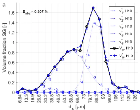
The area and roundness data for the graphite was also used to analyse the size distribution of SG in the specimens. In this case, the SG were defined as all particles with a roundness larger than 0.525. Due to the varying roundness of the particles, the area of the particles was converted to an equivalent diameter 2 / . The size distribution was produced by dividing the particle population into 20 size classes of equal width, where the upper boundary of the largest class corresponded to the equivalent diameter of the largest SG. The sectional size distribution by number density was converted to volumetric size distribution by employing a finite difference method based on continuous size distribution [87]. The number densities were then converted to volume fractions by multiplying by the volume of the average particle in respective size class. A method for estimating subpopulations making up the size distribution was developed. In principle, the size distribution was assumed to be constructed of a number of overlapping subpopulations of Gaussian distribution. The function was fitted to the measured distribution using a minimization scheme, where the sum of absolute error was the objective function.
Primary austenite characterization
The volume fraction and surface area per unit volume of the primary γ structure was measured using two main approaches which were compared. The first approach involved generation of binary images from the micrographs with the help of Adobe Photoshop CS6. The parameters were then measured automatically using the commercial image analysis software Olympus Stream. The method is rapid, however some obvious differences between the binary images and the original micrographs were identified. To estimate how considerably these differences influenced the values of the measured parameters, a second generation of measurements were made where the differences had been manually corrected by careful comparison to the original micrograph. Moreover, the same parameters were measured using traditional point counting and line intercept methods. The point counting was performed by superposing a 22x22 square grid over each micrograph and counting the number of points coinciding with the dendrites. Points on the boundary were counted separately as ½. The point fraction was then calculated
21 as 0.5 ∗ ½ / . The line intercept technique was performed by superposing three concentric circles over the micrograph and counting the number of interception points ∅ between the circles and the dendritic structure. The number of incercept points per unit circle length ∅ was then calculated as
∅/ ∅. was then calculated using the stereological relation 2 [88].
EPMA-WDS
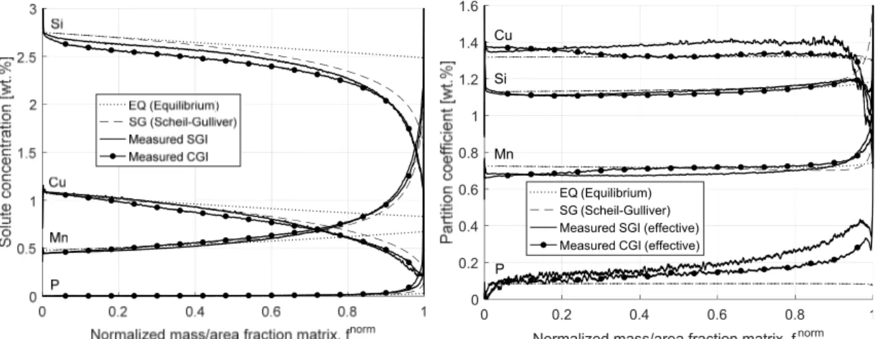
Electron probe micro analysis was applied to alloy H in order to investigate microsegregation. The instrument is a modified ARL‐SEMQ equipped with six WDS spectrometers. It operates at an acceleration voltage of 25 kV and applies a sample current of 6 μA. It was employed to map the distribution of C, Si, Mn, P, Cu and Sn over a 300x300 point raster covering a 3x3 mm area. The concentration data was later treated and visualized using scripts developed in Matlab. Partitioning was investigated by estimating the equilibrium eutectic temperature ∗ calculated using equation 3 in each point in the metal matrix (excluding graphite). The composition in the metal matrix / as a function of area fraction of the metal matrix was calculated by sorting the data points in descending order of ∗. For each point, the average composition in the liquid was estimated as the average composition of all points with a lower ∗. This allowed for estimation of effective partition coefficients as a function of area fraction of the matrix, according to equation 4 . ∗ 1158.86 3.77 3.43 18.93 3.30 3 / 4
23 CHAPTER 3
SUMMARY OF RESULTS
AND DISCUSSION
CHAPTER INTRODUCTION In this chapter, the results are summarized and discussed.THE TRANSITION FROM SPHEROIDAL TO
COMPACTED GRAPHITE IRON
To support discussion of the results, this sections begins with remarks on the influence of the holding time as a means to control the nodularity, including some unintended influences of the variable.
The control of graphite morphology by varying
holding time during remelting of SGI (Supplement I)
The experimental series H10‐H60 was produced by remelting and solidifying alloy H using varying holding times. This resulted in varying fractions of SG and CG as indicated in Figure 3. The method was preferred due to the elimination of the variables involved in direct variation of the spheroidization treatment, making it easier to attribute characteristics to the graphite morphology. The main risk considered was that prolonged holding time would decarburize the melt. The measured area fractions summarized in Figure 4 show no sign of decarburization. The measured percentages of nodularity are summarized in Figure 5, showing a rather linear decay of the value, with some scatter.
24
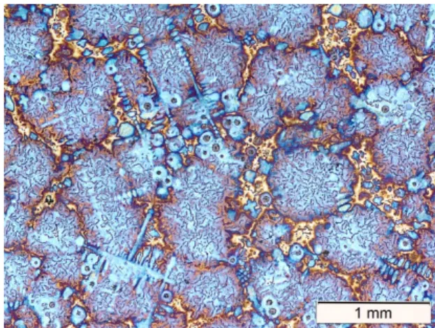
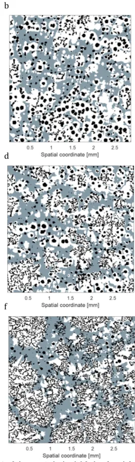
Figure 3. Selected micrographs, illustrating the transition from SGI to CGI with increasing holding time at 1450 °C. a: H10, b: H20, c: H30, d: H40, e: H50, f: H60.
Figure 4. Measured area fraction graphite as a function of holding time. The dashed lines represent the theoretical fraction graphite for the alloy Assuming ferrite and pearlite matrix. Whiskers represent the 95% confidence interval for the mean.
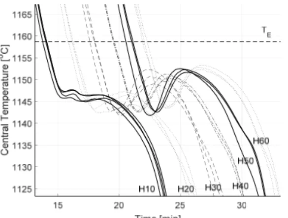
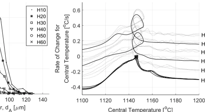
Figure 5. Measured percent nodularity as a function of holding time. Whiskers represent the 95% confidence interval for the mean. Examination of the cooling curves in Figure 6 indicates some unexpected influences of the holding time. First of all, the maximum temperature is slightly lower for H10, meaning the maximum temperature inside the specimen was not reached during the 10 min holding time. Secondly, there is a slight dependency of cooling rate on holding time for H10‐H30. So, while the experimental method was successful in controlling the nodularity, it had some unintended influences which complicates the interpretation of the result. A closer examination of the eutectic region of the cooling curves (Figure 7) reveals some interesting characteristics. The eutectic reaction begins at a higher temperature for H10. SGI is usually associated with higher undercooling due to its low growth rate. The low undercooling of H10 most likely relates to residual undissolved particles in the melt due to the lower maximum temperature and short holding time after remelting.
0 10 20 30 40 50 60 70
Holding Time [min]
0 2 4 6 8 10 12 14 0 10 20 30 40 50 60 70
Holding Time [min]
0 20 40 60 80 100
![Figure 1. Stable and metastable Fe‐C equilibrium phase diagram [4].](https://thumb-eu.123doks.com/thumbv2/5dokorg/4627435.119549/15.892.140.787.99.827/figure-stable-and-metastable-fe-equilibrium-phase-diagram.webp)