Effect of precursor solutions on the structural
and optical properties of sprayed NiO thin films
Mohammed Metwally Gomaa Ahmad, Gholamreza Yazdi, Susann Schmidt, M. Boshta, Volodymyr Khranovskyy, Fredrik Eriksson, B. S. Farag, M. B. S. Osman and Rositsa YakimovaThe self-archived version of this journal article is available at Linköping University Electronic Press:
http://urn.kb.se/resolve?urn=urn:nbn:se:liu:diva-137995
N.B.: When citing this work, cite the original publication.
Ahmad, M. M. G., Yazdi, G., Schmidt, S., Boshta, M., Khranovskyy, V., Eriksson, F., Farag, B. S., Osman, M. B. S., Yakimova, R., (2017), Effect of precursor solutions on the structural and optical properties of sprayed NiO thin films, Materials Science in Semiconductor Processing, 64, 32-38. https://dx.doi.org/10.1016/j.mssp.2017.03.009
Original publication available at:
https://dx.doi.org/10.1016/j.mssp.2017.03.009 Copyright: Elsevier
1
Effect of precursor solutions on the structural and optical
properties of sprayed NiO thin films
M. M. Gomaa, 1, 2* G. RezaYazdi,2* Susann Schmidt,2 M. Boshta,1 V. Khranovskyy,2 F.
Eriksson,2 B. S. Farag,1 M. B. S. Osman,3 R.Yakimova2
1Solid State Physics Dept., National Research Center, El-Behouth st., 12311, Dokki, Giza,
Egypt.
2Department of Physics, Chemistry and Biology, Linköping University, SE-58183 Linköping,
Sweden
3Physics Department, Faculty of Girls, Ain Shams University, Heliopolis, Cairo, Egypt
Corresponding authors: mohme00@ifm.liu.se Tel: +46-737311862, Fax: +46-13-137568,
, yazdi@ifm.liu.se
Abstract:
Nickel oxide thin films were deposited by a simple and low-cost spray pyrolysis technique using three different precursors: nickel nitrate, nickel chloride, and nickel acetate on corning glass substrates. X-ray diffraction show that the NiO films are polycrystalline and have a cubic crystal structure, although predominantly with a preferred 111-orientation in the growth direction and a random in-plane orientation. The deconvolution of the Ni 2p and O 1s core level X-ray photoelectron-spectra of nickel oxides produced by using different precursors indicates a shift of the binding energies. The sprayed NiO deposited from nickel nitrate has an optical transmittance in the range of 60-65%in the visible region. The optical band gap energies of the sprayed NiO films deposited from nickel nitrate, nickel chloride and nickel acetate are 3.5, 3.2 and 3.43 eV respectively.Also, the extinction coefficient and refractive index of NiO films have been calculated from transmittance and reflectance measurements. The average value of refractive index for sprayed films by nickel nitrate, nickel chloride and nickel acetate are 2.1, 1.6 and 1.85 respectively. It is revealed that the band gap and refractive index of NiO films by using nickel nitrate corresponds to the commonly reported values. We attribute the observed behavior in the optical band gap and optical constants as due to the change of the Ni/O ratio.
2 1. Introduction
Transparent conducting oxides (TCOs) thin films, such as; Al-doped zinc oxide (ZnO), indium tin oxide (ITO), Sb-doped SnO2, and In2O3 widely use in solar cells, heat mirrors and windows,
liquid crystal displays, and light-emitting diodes. Most of these TCOs are n-type semiconductors. However, corresponding p-type (p-TCO), with high transmittance and low resistivity which are very important for smart windows, transparent electrodes, optoelectronic devices and transparent electronic devices is still lacking. In 1997 Kawazoe et al. reported first p-type TCO (CuAlO2) in a highly transparent thin film of (CuAlO2), which opened up a new
field in transparent electronics applications [1,2].
Nickel oxide (NiO) is a promising material for p-type transparent conducting oxide films due to its outstanding properties, such as high chemical stability, good crystallinity, wide direct energy gap of 3.6 – 4.0 eV [3], wide spectral range of transparency, and low material cost [4]. Undoped NiO films show resistivity in the order of 1013 cm at room temperature and
this can be decreased significantly for p-doped NiO by increasing of Ni vacancies and/or interstitial oxygen in the NiO structure [5,6]. The behavior of NiO strongly depends on its stoichiometric ratio of nickel to oxygen atoms. Various characteristics of the nickel oxide films change due to their nonstoichiometry, and these characteristic variations have different effects in different applications such as electrochromic material [7], electrode in solar cell [8, 9], an active material in chemical gas sensors [10] and organic light emitting diodes [11].
Up to date, a number of techniques have been advanced in the preparation of nickel oxide thin films, such as dipping and electrochemical, spin coating [12], atomic layer deposition, sol–gel [13], sputtering [14-15], pulsed laser deposition [16], chemical bath deposition [17-19] and chemical spray pyrolysis [20–23]. The most common and sheep fabrication method for large area homogeneous coatings of NiO is chemical spray pyrolysis due to the cancellation of the vacuum system and it is an easy setting up technique. This method is described by uniform size distributions and provides thin films whose grain size is controlled by various parameters such as preparation condition, doping type and concentration. Great works have been done in order to study the effect of the preparation parameters on the properties of the NiO films, such as the effect of thickness [24] and substrate temperature [25]. In this work we have explored the influence of different precursors on the structural and optical
3
properties of sprayed NiO thin films on glass substrates. The obtained results provide valuable information about structural and optical properties of NiO, which is a very helpful issue for better understanding and perfection of the material quality for the electronic application.
2. Experimental Details
2.1. Films preparation
Chemical spray pyrolysis was used to prepare nickel oxide films by using (0.2M) aqueous solution of different precursors; nickel nitrate (Ni(NO3)2·6H2O), nickel chloride (NiCl2·6H2O)
and nickel acetate (Ni(OCOCH3)2·4H2O) on preheated Corning glass (2947) at a temperature
of 450oC. Prior deposition, the glass substrates were ultrasonically cleaned in acetone solution
and rinsed in distilled water to get cleaned surface which important to start nucleation of deposited films. The distance between the nozzle and the substrate was kept at 30 cm. In order to obtain uniform NiO films, the deposition time, and the pressure of the compressed air gas was maintainedfor all samples at 10 min and 1.5 bar, respectively.
2.2. Characterization techniques
The thickness of the prepared films was measured by a Dektak 150 Stylus profilermeter and was found to be 300, 275, 270 nm for NiO by nickel chloride, nickel acetate and nickel nitrate, respectively. The structural properties of the films were assessed by X-ray diffraction (XRD) -2 measurements with a Panalytical X’Pert diffractometer operated in Bragg-Brentano geometry using Cu Kα radiation at 45 kV and 40 mA. A Bragg-Brentano HD mirror was used as a primary optics together with 0.5° divergence and anti-scatter slits, and an X’celerator detector, operating in a scanning line mode on the secondary side. Grazing incidence XRD (GIXRD) and pole figure measurements were conducted using a PANalytical EMPYREAN diffractometer in a parallel beam configuration. For GIXRD a line focused copper anode source (Cu Kα, =1.54 Å), operating at 45 kV and 40 mA, was used, and the primary beam was conditioned using a parallel beam mirror and a 0.5° divergence slit and in the secondary beam path a 0.27° parallel plate collimator was used together with a Ni-filter to remove the K-radiation. For the pole figure measurements the X-ray source was used in point focus mode and an X-ray lens together with crossed-slits, 2x2 mm2, was used to condition the beam together with the same parallel plate collimator, but without the Ni-filter. A PIXcel-3D detector was used as an open detector for the data acquisition. The chemical composition and bonding states
4
of the NiO samples were investigated by X-ray photoelectron spectroscopy (XPS, Axis Ultra DLD, Kratos Analytical, Manchester, UK). The spectrometer was equipped with a monochromatic Al(Kα) X-ray source (hν = 1486.6 eV). XPS core level spectra of Ni 2p, C 1s, and O 1s regions were acquired after sputter cleaning for 600 s with a 500 eV Ar+ beam. For evaluation, the Casa XPS software (version 2.3.16) was used. The spectra were referenced to the C-C bond at 284.5 eV. The Ni2p and O1s core level spectra were closer investigated. Here, all components of the core level spectra were fitted using a Voigt peak shape function with the Lorentzian contribution of 30 %.
The surface morphology of the NiO films were investigated using 10 keV electron beam in a Leo 1550 Gemini scanning electron microscopy. In addition, surface topography of all prepared films was performed in tapping mode by means of an atomic force microscopy (VEECO digital instrument). The optical properties of the prepared films were measured using a dual beam UV– VIS–NIR spectrophotometer (Jasco V750, Japan).
3. Results and discussion
3.1 Structural and chemical properties
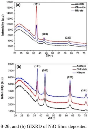
Figure.1 (a) and (b) shows the -2 and grazing incidence patterns, respectively, of deposited NiO films as a function of precursor solutions. The grazing incidence measurement makes it possible to see film peaks that in the -2 measurement have low intensities, in particular for NiO by using nickel acetate. Phase identification and analysis of the -2 scan reveal that all diffraction peaks can be assigned to the same crystal structure, although from these measurements it cannot be determined whether the structure is cubic (pdf no. 047-1049) or rhombohedral (pdf no. 44-1159) since the diffraction peaks for these two crystal structures overlap. However, using pole figure measurements it could be confirmed that the NiO films are cubic, and the diffraction peaks have been labeled with the corresponding Miller indices. The broad peak located at about 2= 24° is interpreted as a contribution from the amorphous glass substrate. From the position of the diffraction peaks lattice parameters of the cubic structure was calculated for the different NiO films and is tabulated in Table 1. As can be seen, there is no significant influence of different precursors on the lattice parameters values.
5
Fig. 1. (a) X-ray diffraction -2, and (b) GIXRD of NiO films deposited using different precursors.
The peak broadening is due to a combination of broadening from the optical conditions of the instrument and the microstructural features in the sample. By measuring a reference standard sample with large grains and no strain, it is possible to determine the broadening caused by the instrument. Here, a Molybdneum (Mo) reference sample provided by Panalytical was used. The 111 diffraction peaks of the NiO films (2~ 37°) and the 110 diffraction peak of the Mo standard sample (2~ 40°) was used for the single line profile analysis. By fitting the peaks with a pseudo-Voigt function the peaks can be deconvoluted into gaussian and lorentzian fractions, and the instrumental effects can be subtracted. The lorentzian contribution to the film peak broadening is related to the size of coherently scattering domains, or the grain size, by the Scherrer equation. The grain size obtained using the 111 diffraction peaks of the NiO is tabulated in Table 1.
Table .1 Structural parameters for sprayed NiO thin films by different precursor solutions.
Nio Precursors Prefered
orintation Lattice constant a(nm) grain size D111 (nm) nickel acetate 111 0.4186 10 nickel chloride 111 0.4179 57 nickel nitrate 111 0.4179 45
6
Comparing the measured peak intensities in the -2 scan with tabulated intensities for a randomly oriented NiO cubic structure, it is clear that the 111 peak is dominating the diffraction pattern, indicating that the films have a predominant 111-preferred orientation. To completely describe the texture of the NiO films, Pole figure measurements of the 111-, 200-, and 220- reflections were performed, and are shown in Fig.2.
For the 111 pole figures intensity is seen in the central of the pole figure, showing that 111 is parallel with the film growth direction. Furthermore, a broad ring of high intensity is shown at an angle of = 70.5°. The measured angle corresponds to the angle between 111 planes in a cubic structure, thus confirming the cubic crystal structure of NiO. The ring shows that the NiO film is textured and the rotational symmetry of the ring suggests a fiber-textured growth on the glass substrate. The preferred orientation is supported by complementary measurements of the 200 and 220 pole figures in Fig. 2b and c. The 200 pole figures display a ring at =54.7°, which is the angle between 200 and 111 planes. The 220 pole figures should show two rings of intensities at =35.26° and 90° corresponding to the angles between 220 and 111 planes. The missing ring of intensity at 35.26° is due to a too low intensity. Azimuthal integration of the intensities in the 220 pole figures (not shown) however clearly reveal a peak at the correct tilt angle. Furthermore, the high -angle ring shows up at a slightly lower angle (~80°) due to defocusing of the beam.
Thus, the films consist of single-phase NiO with a cubic crystal structure and a predominant 111-orientation in the growth direction and a random in-plane orientation.
7
Fig.2. Pole figure measurements of NiO from different precousors (a) 111plane, (b) 200 plane and (c) 220 plane.
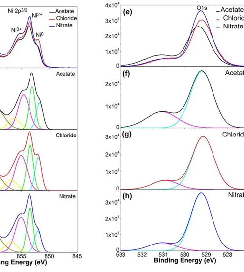
XPS measurements were performed to study the chemical composition i.e., the Ni/O ratio and the chemical bonding states of the sprayed NiO films using different precursors. Fig.3 (a), shows the Ni 2p3/2 core level spectra of the three sets of samples and their deconvolution into Ni2+, Ni3+ and Ni metal contributions. A combined view of the corresponding O1s core level spectra obtained from the NiO samples is shown in Fig. 3 (e).
8
Fig .3 XPS core level spectra of sprayed NiO thin films prepared with different precursors. (a) combined view of Ni 2p3/2 spectra obtained from NiO prepared with nickel acetate, nickel chloride, and nickel nitrate (b) Ni 2p3/2 corelevel spectrum of the film prepared using Acetate (c) Ni 2p3/2core level spectrum of the film prepared using Chloride, (d) Ni 2p3/2 core level spectrum of the film prepared using Nitrate. (e) combined view of O1s core level spectra of the films prepared using nickel acetate, nickel chloride, and nickel nitrate . (f), (g), and (h) show the corresponding O1s core level spectra.
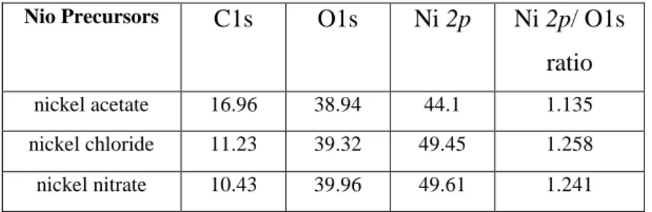
The chemical composition of NiO films is also influenced by atmospheric carbon as shown in table.2. In addition, the comparatively high carbon content of 16.96 % in the NiO film from nickel acetate arises due to its elevated surface roughness (RMS = 31 nm) as discussed in the following section, which promotes the adsorption of ambient carbon and renders sputter cleaning prior to XPS measurements inefficient. Additionally, the main final gas-phase products of the thermal decompositions of nickel acetate, nickel nitrate and nickel chloride are CO2, O2, and HCl, respectively [26-28]. These gases play important role for the Ni/O ratio and
surface morphology of NiO thin films. The CO2 and HCl gases have some drawbacks; such as
9
the NiO thin films by using nickel acetate and nickel chloride, respectively. On the other hand, the O2 gas may improve the properties of NiO thin films by using nickel nitrate.
Table 2. Compostion ratio of sprayed NiO thin films by different precursors
Nio Precursors C1s O1s Ni 2p Ni 2p/ O1s
ratio
nickel acetate 16.96 38.94 44.1 1.135
nickel chloride 11.23 39.32 49.45 1.258 nickel nitrate 10.43 39.96 49.61 1.241
Figures.3 (b-d) and Fig.3 (f-h), show the deconvoluted Ni 2p3/2 and O1s spectra,
respectively. The results are also listed in Table.3. In Fig. 3 (a-d) and Table 3 the differences of the Ni2+/Ni0 as well as Ni2+/Ni3+ intensity ratios are apparent. The contribution arising at 852.0 eV is attributed to Ni0 (metallic Ni) [29], while the contribution at 855 eV can be attributed to Ni+3 states [29]. The Ni 2p3/2 of the NiO prepared using nickel chloride shows a comparatively
high amount of metallic Ni bonds, which is caused by the corrosive chlorine chemistry increasing surface porosity [30]. This surface porosity promotes the adsorption of carbon and hydrogen, which in turn induces the reduction of NiO to Ni [31-33].
The Ni 2p3/2 obtainedfrom the NiO prepared with nitrate shows the highest amounts of
Ni3+and Ni+2 due to oxygen excess from the thermal decomposition of nitrate. Nickel vacancies
created at the cation site can be ionized to create Ni3+ ions serving as acceptors that donate holes of nickel oxide thin films [29]. This is also supported by the corresponding O1s spectra of the sprayed NiO thin film shown in Fig.3(e). The O1s core level spectra were deconvoluted with two contributions (Fig.3f-h); O bond to Ni2+ at a binding energy of 529.2 eV O-C bonds at 531 eV [34]. As shown in Fig.3 (h) the NiO prepared by using nickel nitrate shows less O-C bonds than the sprayed NiO using acetate and chloride (cf. Fig.3f and g). The oxygen contents are in good agreement with the results obtained from the Ni2p spectra. The XPS results confirm that the changes in chemical composition and structure of sprayed NiO films depend on the Ni/O ratio of different precursors.
10
Table 3. XPS results of sprayed NiO thin films by different precursors
NiO Precursor Core level region Peak position (eV) FWHM (eV) Concentration in at% Peak Assignment nickel acetate Ni2p3/2 852.0 1.5 12.79 Ni0 Ni2p3/2 853.4 1.4 18.96 Ni2+ (NiO) Ni2p3/2 855.0 2.5 27.31 Ni3+ O1s 529.2 1.2 72.13 O-Ni O1s 531.1 1.7 27.87 O-C nickel chloride Ni2p3/2 851.9 1.4 14.16 Ni0 Ni2p3/2 853.4 1.4 19.68 Ni2+ (NiO) Ni2p3/2 855.0 2.5 27.42 Ni3+ O1s 529.1 1.2 82.88 O-Ni O1s 530.9 1.4 17.12 O-C nickel nitrate Ni2p3/2 852.0 1.4 9.83 Ni0 Ni2p3/2 853.5 1.3 19.10 Ni2+ (NiO) Ni2p3/2 855.1 2.5 28.38 Ni3+ O1s 529.2 1.1 84.55 O-Ni O1s 531.1 1.5 15.45 O-C 3.2 Surface morphology
The surface morphology of NiO films deposited on glass at 450°C by with different precursors solution was studied by using SEM and AFM. Fig.4 (a) shows typical SEM image of sprayed NiO films by nickel nitrate. The films exhibit excellent adhesion and smooth grainy surface. On the other hand, the sprayed NiO film by nickel chloride and nickel acetate seems to be almost instantaneously leading to those structures of irregular shape like rings. Although rough, neither holes, nor voids are visible in the films, as shown in Fig.4 (b) and (c). In addition, the surface morphology of sprayed NiO films were studied using AFM in tapping mode. The RMS roughness of NiO thin films are 16, 31, and 90 nm for nitrate, acetate, and chloride sources, respectively. The differences in the O/Ni ratio during thermal decomposition of precursor solutions resulting in significant changes in the surface morphology, is discussed in the XPS sections.
11
Fig.4. SEM micrographs of sprayed NiO thin films from, (a) nitrate, (b) chloride, (c) acetate. (d), (e)
and (f) a higher magnefication of an area in (a), (b), and (c), respectivly.
3.3. Optical properties
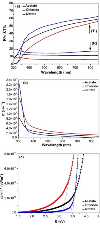
Figure.5(a) shows the optical transmittance and reflectance spectra of sprayed NiO films using different precursors as a function of wavelength from 300-900 nm. It was found that all NiO films are transparent in the visible region. The highest average transmittance value was in the range of 60-65% for the NiO films that were sprayed using nickel nitrate while the other precursors have average transmittance of 45%. The absorption coefficient (α) is calculate using the following formula [35]:
𝛼 =1𝑡ln[(1−𝑅)2𝑇 2+ √(1−𝑅)4𝑇24+ 𝑅2] (1)
Where t is film thickness, T is the transmission and R is the reflectance of NiO films. The absorption coefficient increases with decrease in the wavelength as shown in Fig. 5(b). While, and regarding the variation of absorption coefficient of sprayed NiO films using different precoursors, it found that the films absorbe lower energies. This is due to a spreading of state denisities in the band gap due to defects [36]. in addition, the internal electric field due to the impurities distributions as confirmed by XPS results. The optical band gap energy (Eg) of films
12
𝛼ℎ𝜐 = 𝐴(ℎ𝜐 − Eg)𝑛 (2)
Where α is absorption coefficient, Eg is the band gap, hυ is photon energy, A is constant and n
assumes values of 1/2, 2, 3/2 and 3 for allowed direct, allowed indirect, forbidden direct and forbidden indirect transitions, respectively. Fig.5 (c) shows the value of the optical band gap energy of sprayed NiO thin films using different precursors. The optical band gap energies for NiO deposited using nickel nitrate, chloride and acetate are 3.5 eV, 3.2 eV and 3.43 eV, respectively. The difference of theband gap energies is depends on the degree of crystallinity (table 4) and Ni/O ratio. The change in Ni/O ratio is due to the presence of Ni vacancies and/or oxygen defects as discussed in XPS results.
13
Fig. 5. (a) Optical transmittance and Reflectance, (b) Absorption coeffecient and (c) Plot of (αhν)2 versus (hv) of sprayed NiO films by using different precursors.
Table.4 Effects of precursors on structural, morphological and optical properties of sprayed NiO thin films
Nio Precursor grain size D111 (nm) Roughness (nm) Optical Eg (eV) nickel acetate 10 31 3.43 nickel chloride 57 90 3.2 nickel nitrate 45 16 3.5
14
In addition the refractive index is one of the most important optical constant of a material which depends on the wavelength of electromagnetic wave. In this work the refractive index is calculated using the following formula [35]:
𝑛 =(1+𝑅)(1−𝑅)+ √(1−𝑅)4𝑅 2− 𝑘2 (3)
Where the R is the reflectance and 𝑘 is the extinction coefficient and calculate by using formula:
𝑘 =𝛼𝜆4𝜋 (4)
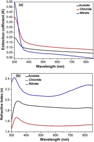
The variation of extinction coefficient (k) as a function of wavelength in range (300-900 nm) of sprayed NiO films by different precursors as shown in Fig.6 (a). It can be seen that the lowest value of (k) for NiO films by using nickel nitrate that indicates to lowest surface roughness, which decrease the scattering losses thereby to increasing the transmitting ability. On the other hand, the (k) value for NiO films by nickel acetate and chloride is high due to high surface roughness and carbon contamination as confirmed by AFM and XPS measurements. Fig. 6 (b) shows the relation between the refractive index and wavelength for sprayed NiO films by using different precursors. It can be seen that the refractive index of NiO films by nickel nitrate values in the range of (2.1-2.3) which is an agreement with reported value due to low roughness and good crystallinity[37]. In addition, the incrasring of Refarctive index of NiO sprayed by nitrate in the end of visible and near IR region is relating to increase of carrier concentration, may be due to oxidation of N2+ to Ni3+ which inhances the p-type character of the films.
15
Fig. 6 (a) Extinction coefficient (k) and (b) Refractive index (n) of sprayed NiO films by using different precursors.
4. Conclusion
NiO thin films were deposited by the chemical spray pyrolysis technique using different precursors: nickel nitrate hexahydrate (Ni(NO3)2·6H2O), nickel chloride hexahydrate
(NiCl2·6H2O), and nickel acetate (Ni(OCOCH3)2·4H2O) on Corning glass substrates. The SEM
and AFM study showed that the surface morphology of NiO thin films is affected by the precursors. NiO films are polycrystalline and have a cubic crystal structure with a preferred 111-orientation in the growth direction and a random fiber textured in-plane orientation. The XRD and XPS results confirm that the changes of initial nucleation, chemical composition and structure of NiO thin films depend on the Ni/O ratio of different precursors.
The sprayed NiO films using nitrate have optical transmittance higher than the sprayed films using chloride and acetate. The optical band gap has been found to change from 3.2, to 3.5 eV. This change is due to the formation of gases (O2, CO2, and HCl), which are generated
16
during the thermal decomposition of the different precursors as. This affects the oxidation and reduction of NiO and changes the Ni/O ratio of the deposited films. The band gap, extinction coefficient and refractive index of the NiO thin films using nickel nitrate is close to the commonly reported value. The sprayed NiO films by using nickel acetate and nickle chloride are sutible for solar cells and gas sensing applications. The sprayed NiO by nitrate have such features as higher crystallinity, lower roughness and higher optical transmission, which make NiO films suitable as p-type transparent conducting oxides for U.V photo-dedectors and LED applications. However, further studies are of interest in order to understand the influence of the other spray parameters on the improvement of the electrical properties of NiO thin films before their applications in electronics.
5. Acknowledgements
The authors acknowledge the financial support by the Collaborative Research Project between Egypt and Sweden funded from the Swedish Research Council (VR 348-2013-6782), Egyptian Ministry for Higher Education and Scientific Research, Ångpanneföreningens Forskningsstiftelse (Grant 14-517) and Swedish Research Council (VR) Marie Skłodowska Curie International Career Grant #2015-00679 ”GREEN 2D FOX”.
6. References
[1] H. Kawazoe, M. Yasukawa, H. Hyodo, M. Kurita, H. Yanagi, H. Hosono, P-type electrical conduction in transparent thin films of CuAlO2, Nature. 389 (1997) 939-942.
[2] G. Thomas, “invisible circuit”, Nature. 389 (1997) 907-908.
[3] Xinman Chen, Lingzhizhao, and Qiaoliniu. Electrical and optical properties of p-type Li,Cu-codoped NiO thin films, Electron Mater. 41 (2012) 3382-3386.
[4] Ratnesh Sharmaa, A.D. Acharyaa, S.B. Shrivastavaa, T. Shripathi, V. Ganesanb, Preparation and characterization of transparent NiO thin films deposited by spray pyrolysis technique, Optik. 125 (2014) 6751-6756.
[5] Chanae Parka , Juhwan Kima , Kangil Leea , Suhk Kun Oha , Hee Jae Kanga, and Nam Seok Park, Electronic, Optical and Electrical Properties of Nickel Oxide Thin Films Grown by RF Magnetron Sputtering, Appl Sci Converg Technol. 24 (2015)72-76.
[6] Dong Soo Kim and Hee Chul Lee, Nickel vacancy behavior in the electrical conductance of nonstoichiometric nickel oxide film, J Appl Phys. 112 (2012) 1-5.
[7] H. Moulki, C. Faure, M.Mihelcic, A.Surca Vuk, F.Svegl,B.Orel, G.Campet, A.V. Chadwick, D. Gianolio,A.Rougier, M. Alfredsson, Electrochromic performances of nonstoichiometric NiO thin films. Thin Solid Films. 553 (2014) 63-66.
[8] S.Y. Park, H.R. Kim, Y.J. Kang, D.H. Kim, J.W. Kang, Organic solar cells employing magnetron sputtered p-type nickel oxide thin film as the anode buffer layer. Sol Energy Mater Sol Cells. 94 (2010) 2332-2336. [9] J. Jung, D.L. Kim, S.H. Oh, H.J. Kim, Stability enhancement of organic solar cells with solution-processed nickel oxide thin films as hole transport layers. Sol Energy Mater Sol Cells.102 (2012)103-108.
17
[10] I. Hotovy, L. Spiess, M. Predanocy, V. Rehacek, J. Racko, Sputtered nanocrystalline NiO thin films for very low ethanol detection. Vacuum. 107(2014) 129-131.
[11] J. Bandara, C.M. Divarathne, S.D. Nanayakkara, Fabrication of n-p junction electrodes made of n-type SnO2 and p-type NiO for control of charge recombination in dye sensitized solar cells. Sol Energy Mater Sol Cells.
81(2004) 429-437.
[12] F. Vera, R. Schrebler, E. Munoz, C. Suarez, P. Cury, A. Gomez, R.Cordova, R.E. Marotti, E.A. Dalchiele, Preparation and characterization of Eosin B- and Erythrosin J-sensitized nanostructured NiO thin film photocathodes.Thin Solid Films. 490 (2005)182-188.
[13] S.R. Nalage, M.A. Chougule, Shashwati Sen, P.B. Joshi, V.B. Patil, Sol-gel synthesis of nickel oxide thin films and their characterization.Thin Solid Films. 520 (2012) 4835-4840.
[14] Y.M. Lu, W.S. Hwang, J.S. Yang, Effects of substrate temperature on the resistivity of non-stoichiometric sputtered NiO x films. Surf Coat Technol. 155(2002) 231-235.
[15] J.L. Yang, Y.S. Lai, J.S. Chen, Effect of heat treatment on the properties of non-stoichiometric p-type nickel oxide films deposited by reactive sputtering Thin Solid Films. 488 (2005) 242-246.
[16] I. Fasaki, A. Koutoulaki, M. Kompitsas, C. Charitidis1. Fasaki I, Koutoulaki A, Kompitsas M, Charitidis C, Structural, electrical and mechanical properties of NiO thin films grown by pulsed laser deposition. Appl Surf Sci.
257 (2010)429-433.
[17] L. Barkat, L. Cattin, A. Reguig, M. Regragui, J.C. Bernede Comparison of the physico-chemical properties of NiO thin films deposited by chemical bath deposition and by spray pyrolysis. Mater Chem Phys. 89 (2005)11-20.
[18] M. Ristova, J. Velveska, M. Ristov, Chemical bath deposition and electrochromic properties of NiO x films Solar Energy Mater. Solar Cells. 71 (2002)219-230.
[19] B. Pejova, T. Kocareva, M. Najdoski, I. Grosdanov, A solution growth route to nanocrystalline nickel oxide thin films. Appl Surf Sci. 271 (2000) 271-278
[20] V. Gowthami, M.Meenakshi a, P.Perumal a, R.Sivakuma b, C.Sanjeeviraja, Preparation of rod shaped nickel oxide thin films by a novel and cost effective nebulizer technique. Mater Sci Semicond Process. 27(2014)1042– 1049.
[21] M. M. Gomaa, M. Boshta, B. S. Farag, M. B. S. Osman, Structural and optical properties of nickel oxide thin films prepared by chemical bath deposition and by spray pyrolysis techniques. J Mater Sci Mater Electron. 27 (2016) 711-717.
[22] M. Jlassi, I. Sta, M. Hajji, H. Ezzaouia, Synthesis and characterization of nickel oxide thin films deposited on glass substrates using spray pyrolysis. Appl Surf Sci. 308 (2014)199-205.
[23] L. Cattin, B.A. Reguig, A. Khelil, M. Morsli, K. Benchouk, J.C. Berne`de, Properties of NiO thin films deposited by chemical spray pyrolysis using different precursor solutions. . Appl Surf Sci. 254 (2008) 5814– 5821.
[24] Safwat A. Mahmoud, Shereen Alshomer, Mou’ad A. Tarawnh, Structural and Optical Dispersion Characterisation of Sprayed Nickel Oxide Thin Films. J Mod Phys. 2 (2011) 1178-1186.
[25] A. Boukhachem, R. Boughalmi, M. Karyaoui, A. Mhamdi, R. Chtourou,K. Boubaker and M. Amlouk, Study of substrate temperature effects on structural, optical, mechanical and opto-thermal properties of NiO sprayed semiconductor thin films. Mater Sci Eng B Solid-State Mater Adv Technol. 188 (2014) 72-77.
[26] J.L. Doremieux, Bull. Soc. Chim. Fr. 5 (1969)1508.
[27] Wolfgang Brockner, Claus Ehrhardt, Mimoza Gjikaj, Thermal decomposition of nickel nitrate hexahydrate, Ni(NO3)2.6H2O, in comparison to Co(NO3)2.6H2O and Ca(NO3)2.4H2O. Thermochim Acta. 456 (2007) 64-68.
[28] P.S. Patil, L.D. Kadam, Preparation and characterization of spray pyrolyzed nickel oxide (NiO) thin films. Appl Surf Sci. 199 (2002) 211-221.
[29] Dong Soo Kim, Hee Chul Lee. Nickel vacancy behavior in the electrical conductance of nonstoichiometric
nickel oxide film. J Appl Phys. 112 (2012) 034504.
[30]. G. Sorell, The role of chlorine in high temperature corrosion in waste-to-energy plants. Mater High Temp.
14 (1997) 207-220.
[31].Giuseppe Parrava, the Reduction of Nickel Oxide by Hydrogen J. Am. Chem. Soc. 74 (1952) 1194–1198. [32] Q. Jeangros , C. D. Damsgaard, C. Hebert, T. W. Hansen, J. B. Wagner, R. E. Dunin-Borkowski J. Van herle, A. Hessler-Wyser Reduction of nickel oxide particles by hydrogen studied in an environmental TEM. J Mater Sci.
18
[33] Boris V. L’vov, Andrew K. Galwey The mechanism and kinetics of NiO reduction by hydrogen Thermochemical approach. J Therm Anal Calorim. 110 (2012) 601-610.
[34] A. N. Mansour, Characterization of NiO by XPS. Surf Sci Spectra. 3 (1994) 231-238.
[35] Ratnesh Sharma, A.D. Acharya , Shweta Moghe , S.B. Shrivastava , Mohan Gangrade, T Shripathi , V. Ganesan, Effect of cobalt doping on microstructural and optical properties of nickel oxide thin films, Mater Sci Semicond Process 23 (2014) 42–49.
[36]A. Loukil, A.Boukhachem, M. Ben Amor, M.Ghamnia, K. Raouadi, Effects of potassium incorporation on the structural, optical, vibrational and electrical properties of NiO sprayed thin films for p-type optical windows. Ceram Int 42 (2016) 8274-8289.
[37] Selma Dendouga, Said Benramache, Said Lakel, Influence of Film Thickness on Optical and Electrical Properties of Nickel Oxide (NiO) Thin Films. J. chem. mater. res. 5(2014) 78-84.