SKI Report 00:13
A Study of Criticality in a
Spent Fuel Repository Based
on Current Canister Designs
Timothy Hicks
Anthony Prescott
SKI Report 00:13
A Study of Criticality in a
Spent Fuel Repository Based
on Current Canister Designs
Timothy Hicks
1Anthony Prescott
21
Galson Sciences Limited,
5 Grosvenor House, Melton Road,
Oakhams, Rutland LE15 6AX, UK
2
AEA Technology Nuclear Science,
RD1 Risley,
Warrington, Cheshire WA3 6AT, UK
Summary
SKB’s concept for underground disposal of spent fuel includes requirements on the repository’s barrier system that are aimed at ensuring long-term safety. This report is concerned with the requirement on disposal canister design that there is no risk of criticality in the event of water entering the canister after disposal. In particular, recent changes in disposal canister design have led to the need to re-evaluate the possibility of a criticality excursion occurring after disposal. This report presents the results of criticality calculations that have been performed based on current disposal canister designs, and presents the findings of reviews of previous criticality studies that were undertaken as part of the Swedish repository development programme.
Under the current reference design, the canister will comprise an outer layer of copper and a cylindrical insert of cast nodular iron. Channels for the fuel assemblies will be created by casting steel pipes into the nodular iron. The pipes will be welded together to a cassette and placed in the centre of the casting mould. Recently, the steel cassette has been modified by the introduction of cooling tubes to improve the casting process.
Criticality calculations have been undertaken for spent fuel disposal canisters under repository conditions. The calculations involved determining the neutron multiplication factor for various disposal configurations, depending on the type of canister and fuel assemblies, the initial fuel enrichment, the amount of fuel burn-up, and the amount of burnable poison present. In particular, canisters were assumed to fail at some time after disposal, such that water entered the canister and filled the voids, including the cooling tubes in the canister.
Canisters containing various Boiling-Water Reactor (BWR) and Pressurized-Water Reactor (PWR) spent fuel assemblies were assessed. The reference case for each fuel type assumed a burnup of 40,000 MWd/tHM (megawatt-days per tonne of heavy metal), a 40-year storage period prior to disposal, and canister failure immediately after disposal. Under these reference conditions, all disposal canisters exhibited a large margin of subcriticality. Furthermore, the BWR canisters were found to be subcritical for all values of fuel burnup considered (including unirradiated fuel). PWR canisters were also determined to be subcritical for all values of burnup, provided that pins containing burnable poison were present. However, if burnable poison pins were not present, then canisters containing unirradiated PWR assemblies were found to have an inadequate margin of subcriticality. The spent-fuel repository development programme in Sweden has included previous criticality studies by Behrenz and Hannerz (1978) and Oversby (1996). These studies focused on evaluating plutonium and uranium criticality excursions in which fissile material became concentrated at various locations in the repository (canister, deposition hole, or
appropriate for the current disposal concept in Sweden, although there are some uncertainties concerning details of the analyses.
The results of the previous analyses (Behrenz and Hannerz, 1978; Oversby, 1996) depend on the geometric and material properties of the disposal canisters and barriers, as well as on radionuclide transport and retention processes. Most parameter values used are reasonably conservative with respect to the potential for criticality. For the criticality scenarios addressed, remaining concerns relate to the significance of changes in the arrangements, dimensions, and numbers of spent fuel rods to be placed in each canister. For example, the sensitivity of the neutron multiplication factor to these parameters for scenarios involving the formation of a critical mass of plutonium slurry in a canister has not been determined. Also, the influence of these parameters on the rate of removal of dissolved uranium from the canisters is uncertain. However, based on the generally large margins of sub-criticality determined in the previous analyses, it is unlikely that modifications to canister design will have a substantial effect on the results of the earlier work.
Contents
1 INTRODUCTION ...1
2 CURRENT CANISTER DESIGNS ...3
3 CRITICALITY CALCULATIONS ...6
3.1 Modelling Strategy...7
3.1.1 Modelling Assumptions for Burnup Calculations ...8
3.1.1.1 Svea 64 BWR Assembly...8
3.1.1.2 Svea 100 BWR Assembly...10
3.1.1.3 F 17*17 PWR Assembly Containing No Burnable Poison ...10
3.1.1.4 F 17*17 PWR Assembly Containing Burnable Poison ...12
3.1.1.5 MOX Assembly ...12
3.1.2 Modelling Assumptions for the Repository Calculations ...14
3.2 Results ...16
3.2.1 Svea 64 BWR Assembly ...16
3.2.2 Svea 100 BWR Assembly ...19
3.2.3 F 17*17 PWR Assembly Containing no Burnable Poison...19
3.2.4 F 17*17 PWR Assembly Containing Burnable Poison ...23
3.2.5 MOX BWR Assembly...23
3.3 Summary ...25
4 REVIEW OF PREVIOUS CRITICALITY ANALYSES ... 28
4.1 Canister Design ...28
4.2 Plutonium Criticality...28
4.2.1 Plutonium Criticality Inside a Canister ...30
4.2.2 Plutonium Criticality Outside a Canister ...32
4.2.3 Autocatalytic Criticality ...33
4.3 Uranium Criticality...33
4.3.1 Uranium Criticality in a Tunnel ...34
4.3.2 Uranium Criticality in a Deposition Hole ...34
4.3.3 Analogy with the Oklo Natural Reactors...35
5 CONCLUSIONS... 37
1 Introduction
The Swedish Nuclear Fuel and Waste Management Company, SKB, is undertaking a programme of work aimed at designing an underground repository for the safe disposal of long-lived radioactive waste, including spent fuel generated by the Swedish nuclear power programme. SKB has adopted a multibarrier repository concept (known as KBS-3) comprising the spent fuel itself, a corrosion-resistant canister, a bentonite buffer, and a crystalline host rock (SKB, 1999). The disposal concept includes specific requirements of each component of the barrier system, aimed at ensuring the long-term safety of the repository. This report is concerned with the requirement on canister design that there is no risk of criticality in the event of water entering a canister after disposal. The report presents the results of a criticality study undertaken by Galson Sciences Limited on behalf of the Swedish Nuclear Power Inspectorate (SKI), in the light of recent advances in disposal canister design (Werme, 1998).
The criticality study comprised two tasks. First, criticality calculations were undertaken for spent fuel disposal canisters under possible repository conditions. These calculations were based on SKB’s current designs for the Boiling-Water Reactor (BWR) spent fuel canister and the Pressurized-Water Reactor (PWR) spent fuel canister (which are described in Section 2). Neutron multiplication factors were calculated for various disposal configurations, depending on the type of canister and fuel assemblies, the initial fuel enrichment, the amount of fuel burn-up, the amount of burnable poison present, and the canister failure time (canister failure implies that water enters the canister and fills all voids). Two types of BWR assemblies were studied: the ABB Svea 64 assembly with no burnable poison and the ABB Svea 100 assembly with burnable poison (gadolinium oxide). The PWR assemblies studied were the Framatome F 17*17 assembly with burnable poison (gadolinium oxide) and the Framatome F 17*17 assembly without burnable poison. In addition, a MOX assembly was considered, with a similar configuration to the ABB Svea 64 assembly. The criticality calculations were undertaken by AEA Technology (under sub-contract to Galson Sciences) using the neutron transport code, MONK (AEAT, 1999). The results of these calculations are presented in Section 3 of this report.
The second task involved reviewing two previous criticality assessments that were undertaken by Behrenz and Hannerz (1978) and Oversby (1996) as part of the repository development programme in Sweden. Consideration was given to the potential significance of changes in disposal canister design on the results of these earlier assessments. The results of the review task are presented in Section 4 of this report.
2 Current Canister Designs
A general design for a Swedish repository has been defined, which involves boring vertical deposition holes from tunnels at a depth of about 500 m in crystalline rock (e.g., SKB, 1999). A cylindrical copper canister containing spent nuclear fuel will be placed in each deposition hole and the canister will be surrounded by bentonite clay. As the repository programme has progressed, design modifications have been made to engineered components of the barrier system in order to optimize repository performance.
Werme (1998) described the design premises for the current reference canister for spent fuel, and Andersson (1998) presented minor modifications to this design. Copper has been selected as a canister material, primarily because it has favourable corrosion properties under the oxygen-free conditions expected on the timescale of concern for safe disposal. However, the yield strength of a pure copper canister would not be sufficient to withstand the loads expected under repository conditions. Thus, an insert of sufficiently strong material is required to provide the canister with the necessary mechanical strength. The current reference canister design includes a cylindrical insert of cast nodular iron.
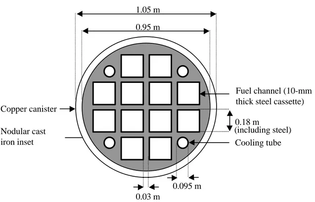
The fuel assemblies are placed in individual channels in the canister. These channels are created by casting steel pipes (with square profiles) into the nodular iron. The pipes are welded together to form a “cassette” for the fuel assemblies, and placed in the centre of the casting mould. A steel lid covers the channels at the top of the insert. Recently, test casting of canister inserts has led to a revision of the canister design (Andersson, 1998). The steel cassette has been modified by the introduction of cooling tubes at locations where material concentrations can occur during casting. The purpose of the cooling tubes is to allow a more uniform solidification and cooling process with reduced risk of cast defects occurring. Each canister will be able to hold either 12 BWR assemblies or 4 PWR assemblies. The reference canister designs for BWR assemblies and PWR assemblies are shown in Figures 1 and 2, respectively. Each canister is 4.83 m long and 1.05 m in diameter, and has a copper lid and bottom. The thickness of the copper for each design is 50 mm, which satisfies the requirement that the total metal cover should be at least 100 mm for radiation shielding. This wall thickness is also expected to provide sufficient corrosion protection. A radial gap of about a millimetre will exist between the insert and the copper shell after manufacture, but the copper shell is expected to deform when a load is applied after repository closure, until it is supported against the insert. The cassette for the fuel assemblies and cooling channels is made of 10-mm thick steel.
Figure 1. Canister design for 12 BWR spent fuel assemblies (Andersson, 1998). 0.95 m 1.05 m Cooling tube Copper canister Nodular cast iron inset 0.16 m 0.25 m 0.08 m 0.08 m 0.03 m (including steel) Fuel channel (10-mm thick steel cassette) 0.95 m 1.05 m Cooling tube Copper canister Nodular cast iron inset 0.03 m 0.18 m 0.095 m (including steel) Fuel channel (10-mm thick steel cassette)
3 Criticality Calculations
As discussed in Section 1, the spent fuel disposal concept in Sweden includes specific requirements on each component of the repository barrier system. The requirements on the canister include a configuration such that the fuel in the canister remains subcritical even if water enters the canister. Water entering the canister would act as a neutron moderator and, therefore, would promote criticality. To prevent criticality occurring, the quantity of water the canister can hold must be limited, or suitable neutron absorbers must be incorporated in the canister. Recent modifications to the BWR and PWR spent fuel canister designs involve the incorporation of cooling tubes in the canisters (see Section 2). These tubes provide additional void space that could become filled with water and affect the potential for criticality occurring. This section presents the results of calculations to determine the reactivity of the canisters based on the current canister designs. Results are presented for cases in which the void space in the canisters, including the cooling tubes, becomes filled with water after disposal.
The criticality calculations involved determination of the neutron multiplication factor for various disposal configurations, depending on the type of canister and fuel assemblies, the initial fuel enrichment, the amount of fuel burn-up, the amount of burnable poison present, and the canister failure time. Canister failure implies that water enters the canister through a crack in the copper and penetrates the iron insert, filling the space between fuel rods in all fuel compartments and any other voids. Canister failure directly after disposal, and 1,000 years and 100,000 years after disposal, was considered.
Two types of BWR assembly were studied: the ABB Svea 64 assembly with no burnable poison and the ABB Svea 100 assembly with burnable poison (gadolinium oxide). An
average initial enrichment of 3.3% 235U was assumed. The Framatome F 17*17 PWR
assembly was also assessed, both with and without burnable poison. An initial enrichment
of 3.17% 235U was assumed for the PWR fuel (although an enrichment of 3.7% was also
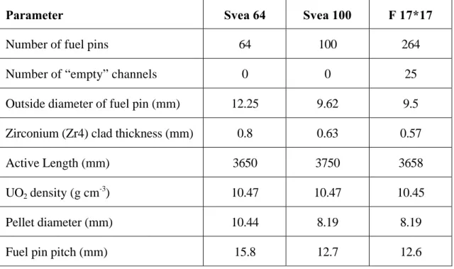
considered). In addition, a MOX assembly was considered with a similar configuration to the ABB Svea 64 BWR assembly with no burnable poison. The MOX fuel pins were assumed initially to contain 5% plutonium. The reference case for each fuel type assumed a burnup of 40,000 MWd/tHM (megawatt-days per tonne of heavy metal). SKB (1997) reported average burnups of 38,000 MWd/tHM and a maximum burnup of 60,000 MWd/tHM for BWR and PWR fuel. The reference case also assumed a 40-year storage period prior to disposal. Descriptions of the various BWR and PWR fuel pins and assemblies are provided in Table 1.
Table 1. Parameters for BWR (Svea 64 and Svea 100) and PWR (F 17*17) fuel assemblies.
Parameter Svea 64 Svea 100 F 17*17
Number of fuel pins 64 100 264
Number of “empty” channels 0 0 25
Outside diameter of fuel pin (mm) 12.25 9.62 9.5
Zirconium (Zr4) clad thickness (mm) 0.8 0.63 0.57
Active Length (mm) 3650 3750 3658
UO2 density (g cm -3
) 10.47 10.47 10.45
Pellet diameter (mm) 10.44 8.19 8.19
Fuel pin pitch (mm) 15.8 12.7 12.6
3.1 Modelling Strategy
The modelling approach involved two stages. In the first stage, burnup calculations (up to 40,000 MWd/tHM) were undertaken using the MONK Monte Carlo neutronics code (version MONK8A). These burnup calculations determined the neutron multiplication factor for fuel assemblies under typical reactor conditions, and produced sets of number densities (atoms x 1024 per cm3) for the irradiation chains of nuclides. The MONK analysis used nuclear data in 69 neutron energy groups obtained from the WIMS Multigroup data library (AEAT, 1999). The WIMS library has been specifically designed for reactor physics analysis, and produces sets of nuclear data for fuel undergoing burnup.
The MONK calculations were continued to determine the nuclide number densities of fuel assemblies at different times after irradiation (burnup) had finished. Calculations were continued for 40 years to determine nuclide number densities after storage in cooling ponds prior to transportation to a repository, and for up to 100,000 years to determine nuclide number densities after disposal.
These calculations provided initial conditions for the second stage of the analyses, in which MONK calculations were undertaken to determine the reactivity of spent fuel assemblies placed in canisters in an underground repository.
3.1.1 Modelling Assumptions for Burnup Calculations
Several modelling assumptions were made in order to perform the burnup calculations for each type of fuel assembly. These assumptions were based on typical reactor operating conditions, or were made in order to simplify the model geometry. The modelling assumptions are described in this section for the different BWR and PWR fuel assemblies.
3.1.1.1 Svea 64 BWR Assembly
The fuel pin configuration that was adopted for the initial burnup calculation for the Svea 64 fuel assembly is illustrated in Figure 3. The Svea 64 fuel assembly contains no burnable poison. Key assumptions concerning reactor conditions and modelling approximations are as follows:
• The power rating for irradiation (burnup) was 25 MW/tHM, and irradiation continued
with no shutdown periods.
• The fuel temperature during irradiation was 780 K, the clad and shroud temperature was 600 K, and the coolant water temperature was 560 K.
• The void fraction in the water at reactor operating temperatures was 50%. This factor was accounted for in the model by assuming a water density of 0.5 g cm-3.
• The coolant water contained no boric acid.
• A 2.5-mm thick zirconium shroud covered each fuel pin array, and a 2-mm thick gap
containing water existed between the outside of the fuel pin array and the shroud. A water-filled gap of 13.2 mm existed between adjacent shrouded assemblies.
• The fuel assembly was divided into outer and inner pins, with the outer pins in contact with water.
• The outer layers of a fuel pin tend to burnup at a faster rate than the centre of the pin. Thus, all pins were divided radially into three regions, to allow simulation of this variation of irradiation within the pins.
• The active length of the fuel pins was assumed to be infinite with appropriate boundary reflection conditions in an infinite system of assemblies.
• Each assembly contained 209 kg of UO2 at an average initial enrichment of 3.3 wt% (the
weight percentage of 235U within the uranium) throughout all pins. The variation of uranium enrichment with axial length of the pins was not considered.
Pin with uranium enrichment of 3.3 wt%.
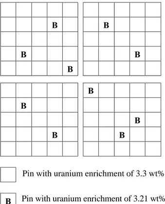
Figure 3. Fuel pin map for the Svea 64 BWR assembly containing no burnable poison.
B B B B B B B B B B
Pin with uranium enrichment of 3.3 wt%.
Pin with uranium enrichment of 3.21 wt% and burnable poison content of 3.15 wt% Gd2O3.
Figure 4. Fuel pin map for the Svea 100 BWR assembly containing burnable poison. The
3.1.1.2 Svea 100 BWR Assembly
The fuel pin configuration that was adopted for the initial burnup calculation for the Svea 100 fuel assembly, which includes burnable poison, is illustrated in Figure 4. Similar operating and modelling assumptions were made for the Svea 100 assembly as were made for the Svea 64 assembly, with the following additional considerations relating to the inclusion of burnable poison:
• When burnable poison is present, the variation in irradiation across a fuel pin is greater than when no burnable poison is present. Thus, pins with burnable poison were divided radially into six regions to allow simulation of this more pronounced ‘skin’ effect.
• The average uranium enrichment was 3.3 wt% throughout all pins that did not contain any burnable poison (90 pins). For the 10 pins containing burnable poison, the enrichment was 3.21 wt%, with 3.15 wt% Gd2O3 as burnable poison. Each assembly
contained 207 kg of UO2 and Gd2O3 (assuming Gd2O3 has the same density as UO2).
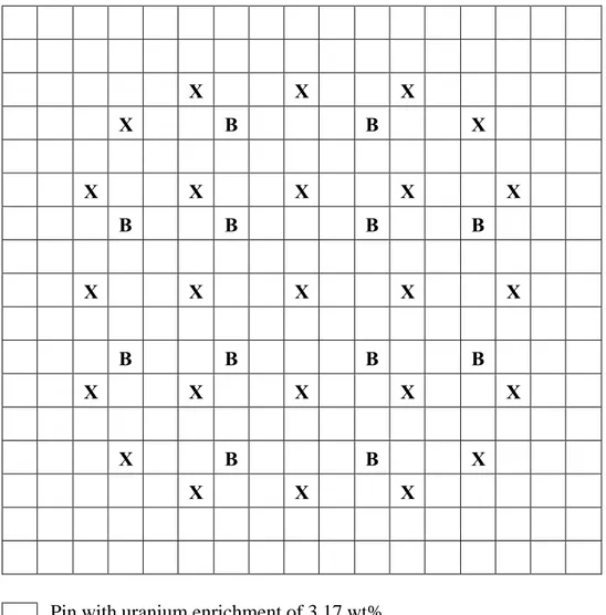
3.1.1.3 F 17*17 PWR Assembly Containing No Burnable Poison
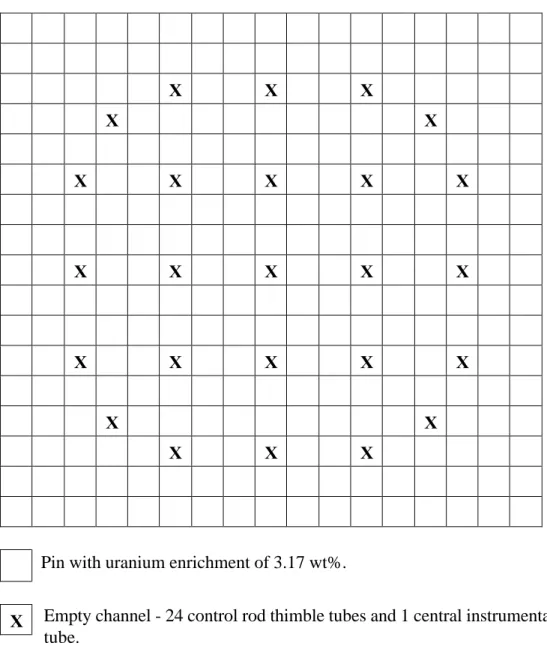
The fuel pin configuration that was adopted for the initial burnup calculation for the F 17*17 PWR fuel assembly is illustrated in Figure 5. The modelling approach taken for the PWR fuel assembly was similar to that taken for the BWR assemblies, but the following reactor conditions were assumed:
• The power rating for irradiation (burnup) was 40 MW/tHM, and irradiation continued
with no shutdown periods.
• The fuel temperature during irradiation was 800 K, the clad and shroud temperature was 580 K, and the coolant water temperature was 580 K.
• The water density was 0.709 g cm-3
.
• The coolant water contained 800 ppm boron. The amount of boron (non-burnable 10
B) in the water was kept constant throughout the irradiation.
• A water-filled gap of 4.5 mm existed between adjacent assemblies.
• Each assembly contained 532 kg of UO2 at an average uranium enrichment of 3.17 wt%
X X X X X X X X X X X X X X X X X X X X X X X X X
Pin with uranium enrichment of 3.17 wt%.
Empty channel - 24 control rod thimble tubes and 1 central instrumentation thimble tube.
Figure 5. F 17*17 PWR assembly containing no burnable poison.
3.1.1.4 F 17*17 PWR Assembly Containing Burnable Poison
The fuel pin configuration that was adopted for the burnup calculation for the F 17*17 PWR fuel assembly containing burnable poison is illustrated in Figure 6. The following modelling assumptions were made relating to the inclusion of burnable poison:
• When burnable poison, is present the variation in irradiation across a fuel pin is greater than when no burnable poison is present. Thus, pins with burnable poison were divided radially into six regions to represent this more pronounced ‘skin’ effect.
• The average uranium enrichment was 3.17 wt% throughout all pins that did not contain any burnable poison (252 pins). For the 12 pins containing burnable poison, the enrichment was 1.38 wt%, with 3.85 wt% Gd2O3 as burnable poison. Each assembly
contained 532 kg of UO2 and Gd2O3 (assuming Gd2O3 has the same density as UO2).
3.1.1.5 MOX Assembly
The MOX assembly was assumed to have a configuration similar to that of the Svea 64 BWR assembly. The assemblies differed only in fissile material content. The Svea 64 assembly had UO2 as the fissile material at the start of the irradiation sequence, whereas the
following assumptions were made relating to fissile material content of the MOX assemblies:
• The plutonium composition of the MOX fuel pins was 63 wt% 239
Pu, 23 wt% 240Pu, 9 wt% 241Pu, and 5 wt% 242Pu.
• The uranium enrichment in the MOX pins was 0.35 wt%.
• The plutonium fissile content of the MOX pins (i.e., the percentage of 239
Pu and 241Pu in the total mass of uranium and plutonium in the pins) was 3.6 wt%, which equates to a total plutonium content of 5 wt% in the pins.
X X X X B B X X X X X X B B B B X X X X X B B B B X X X X X X B B X X X X
Pin with uranium enrichment of 3.17 wt%
Pin with uranium enrichment of 1.38 wt% and burnable poison content of 3.85 wt% Gd2O3.
Empty channel - 24 control rod thimble tubes and 1 central instrumentation thimble tube.
Figure 6. F 17*17 PWR assembly containing burnable poison.
B X
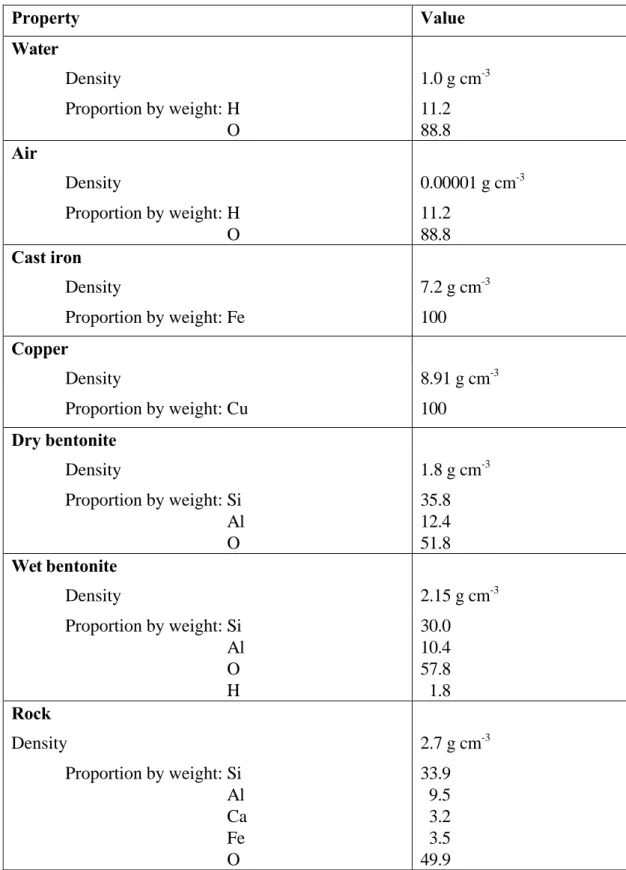
3.1.2 Modelling Assumptions for the Repository Calculations
The model to determine the neutron multiplication factor for BWR and PWR spent fuel canisters in a repository required various geometric and material properties of the barrier system. According to the KBS-3 repository design, discussed in Section 2, cylindrical copper canisters containing irradiated fuel assemblies were assumed to be placed in boreholes in crystalline rock and surrounded by bentonite clay.
Cross-sections of the BWR and PWR canisters are illustrated in Figures 1 and 2, respectively. The active length of each fuel assembly was assumed to be centred axially and radially within a canister insert. Each canister was assumed to be surrounded by a 350-mm thick bentonite buffer, with 1500 mm of bentonite above the canister and 500 mm of bentonite below the canister (SKB, 1999). The canisters were assumed to form an infinite two-dimensional planar lattice, on a pitch of 6 m in the host rock. The model included a rock thickness of 5 m above and below the deposition holes. For cases in which water was assumed to have entered the canister, the bentonite was considered to be water saturated. The properties of the bentonite, rock and canister materials used in the calculations are listed in Table 2 (Pusch, 1998; Byegård et al., 1998). The main elements of each component have been included. For the neutron transport calculations, air was represented by very low density water.
Other assumptions relevant to the canister criticality calculations are as follows:
• The variation of the neutron multiplication factor with irradiation and cooling is
attributed to the change in actinides and the formation of fission products. However, the repository criticality calculations have been based solely on the change in actinides, defined as depletion. Fission products capture neutrons and therefore their omission is pessimistic (i.e., leads to a higher value of the neutron multiplication factor).
• The WIMS library adopted for the criticality calculations does not account for
branching of all the nuclide chains during irradiation. The main branches of concern are accounted for, but actinides with atomic numbers higher than that of americium are not included. The formation of the higher actinides would have a minor effect on the neutron multiplication factor.
• The decay chain from americium is not included in the WIMS library. Therefore, as
241
Am is formed (as a result of the decay of 241Pu) it does not decay. This is of little consequence for the irradiation sequence followed by relatively short cooling times of up to 40 years, because 241Am has a half-life of 432 years. However, when considering longer times (i.e. of the order of 1,000 and 100,000 years), decay of the neutron-absorbing americium may be significant. Therefore, a bounding calculation was undertaken to provide an indication of the significance of amercium decay. This calculation involved the exclusion of all the americium predicted by the initial burnup calculations.
Table 2. Material specifications for repository calculations. The main elements of each component have been included.
Property Value Water Density 1.0 g cm-3 Proportion by weight: H O 11.2 88.8 Air Density 0.00001 g cm-3 Proportion by weight: H O 11.2 88.8 Cast iron Density 7.2 g cm-3 Proportion by weight: Fe 100 Copper Density 8.91 g cm-3 Proportion by weight: Cu 100 Dry bentonite Density 1.8 g cm-3 Proportion by weight: Si Al O 35.8 12.4 51.8 Wet bentonite Density 2.15 g cm-3 Proportion by weight: Si Al O H 30.0 10.4 57.8 1.8 Rock Density 2.7 g cm-3 Proportion by weight: Si Al Ca Fe 33.9 9.5 3.2 3.5
• The repository calculations assume that no damage occurs to the fuel assemblies during the cooling period. Accident scenarios involving disruption of the structure of a fuel assembly have not been considered. Also, the effects of possible variations in pin pitch, canister corrosion, and preferential movement of fissile species, actinides and fission products from the fuel assembly have not been investigated.
3.2 Results
The results of the burnup calculations and repository calculations for the BWR and PWR spent fuel are presented in this section. The reference scenario for the repository calculations assumed a burnup of 40,000 MWd/tHM, a 40-year storage period prior to disposal, and canister failure immediately after disposal.
For the repository calculations, the value of K + 3σ is provided, where K is the neutron multiplication factor, and σ is the statistical standard deviation associated with K. The value of 3σ equates to a probability approaching one in a thousand of K + 3σ being exceeded. Safety assessments using MONK typically assume a 5% margin of subcriticality, after taking into account the statistical uncertainty, σ, on K, such that the safety criterion is K + 3σ ≤ 0.95.
3.2.1 Svea 64 BWR Assembly
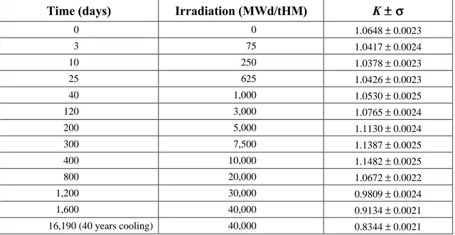
The results for the Svea 64 BWR assembly, which contains no burnable poison, are given in Tables 3 and 4. Table 3 lists the variation of the neutron multiplication factor with irradiation and subsequent cooling. As irradiation increased, the neutron multiplication factor decreased and, thus, the most reactive state for the assembly was when the fuel was unirradiated. The neutron multiplication factor reduced from an initial value of 1.3490 to 0.9227 after 1,600 days, at which time the burnup was 40,000 MWd/tHM at a power rating of 25 MW/tHM. After 40 years of cooling the neutron multiplication factor reduced to 0.8398. The nuclide number densities determined by the burnup and cooling calculations provided initial conditions for the repository calculations. The cooling calculations were continued for up to 100,000 years in order to provide initial nuclide number densities for calculations to determine the reactivity of canisters that had been in a repository for such a period.
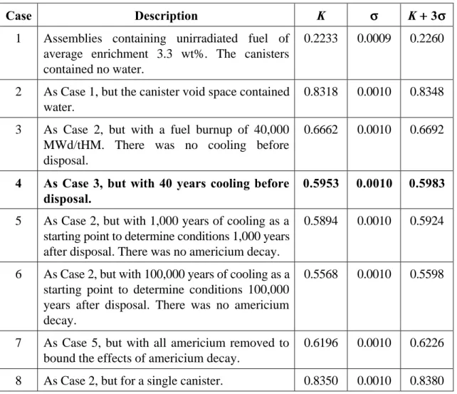
Table 4 shows the calculated neutron multiplication factor for disposal canisters containing 12 Svea 64 BWR assemblies (representing about 2.5 x 10³ kg of original enriched uranium). Examples are shown for canisters at different times after disposal and under different repository conditions. The effect of water within the canister is apparent through inspection of the results for Cases 1 and 2 for unirradiated fuel. Inclusion of water in the canister void space resulted in neutron thermalization in the vicinity of the fissile species, and caused a
Table 3. Neutron multiplication factor as a function of irradiation and cooling time for the Svea 64 BWR fuel assembly containing no burnable poison.
Time (days) Irradiation (MWd/tHM) K ±±σσ
0 0 1.3490 ± 0.0024 400 10,000 1.1696 ± 0.0022 800 20,000 1.0697 ± 0.0022 1,200 30,000 0.9902 ± 0.0024 1,600 40,000 0.9227 ± 0.0024 16,190 (40 years cooling) 40,000 0.8398 ± 0.0022 366,350 (~103 years) 40,000 0.8372 ± 0.0024 36,476,600 (~105 years) 40,000 0.7861 ± 0.0023
Table 4. Results of repository calculation for canisters containing Svea 64 BWR assemblies. The reference case is highlighted.
Case Description K σσ K ++ 3σσ
1 Assemblies containing unirradiated fuel of
average enrichment 3.3 wt%. The canisters contained no water.
0.2233 0.0009 0.2260
2 As Case 1, but the canister void space contained
water.
0.8318 0.0010 0.8348
3 As Case 2, but with a fuel burnup of 40,000
MWd/tHM. There was no cooling before disposal.
0.6662 0.0010 0.6692
4 As Case 3, but with 40 years cooling before disposal.
0.5953 0.0010 0.5983
5 As Case 2, but with 1,000 years of cooling as a
starting point to determine conditions 1,000 years after disposal. There was no americium decay.
0.5894 0.0010 0.5924
6 As Case 2, but with 100,000 years of cooling as a
starting point to determine conditions 100,000 years after disposal. There was no americium decay.
0.5568 0.0010 0.5598
7 As Case 5, but with all americium removed to
bound the effects of americium decay.
0.6196 0.0010 0.6226
Results for Case 3 show the substantial reduction in reactivity associated with a burnup of 40,000 MWd/tHM, and results for Case 4 (the reference case for this assembly) show further reductions associated with a 40-year cooling period prior to disposal. For the reference case, each BWR canister contained 12.5 kg of 239Pu.
The neutron multiplication factors shown for Cases 5 and 6 represent conditions 1,000 years and 10,000 years after disposal, respectively. As discussed in Section 3.1.2, the repository calculations neglect the effects of americium decay. For Case 7, all americium was assumed to be removed as it was formed. Case 7 presents a bounding analysis that gives an indication of the possible effects of americium decay on reactivity. Thus, decay of americium results in an increase in the neutron multiplication factor. For Case 8, a single canister was modelled in order to assess the extent of neutron interaction between neighbouring disposal canisters. Results for Case 8 and Case 2 show no difference in reactivity within statistical uncertainties. Hence, there is no neutron interaction between neighbouring disposal canisters. The results for the Svea 64 BWR indicate a large margin of subcriticality.
3.2.2 Svea 100 BWR Assembly
The results for the Svea 100 BWR assembly, which contains burnable poison, are given in Tables 5 and 6. Table 5 lists the variation of the neutron multiplication factor with irradiation and subsequent cooling. The burnable poison was preferentially lost during irradiation because it has a large neutron capture cross-section. Thus, as the burnable poison was used, the neutron multiplication factor stabilized and then increased to a maximum of 1.1482 at a burnup of approximately 10,000 MWd/tHM. Subsequently, the depletion of the fissile species and further fission product formation resulted in a decrease in the neutron multiplication factor.
Table 6 shows the calculated neutron multiplication factor for disposal canisters containing
12 Svea 100 BWR assemblies (representing about 2.5 x 10³ kg of original enriched
uranium). For a fuel burnup of 40,000 MWd/tHM and a cooling time of 40 years before disposal (Case 10, the reference case for this assembly), the repository calculations indicate a large margin of subcriticality. For Case 11, canisters containing assemblies with the highest reactivities (occurring at a burnup of 10,000 MWd/tHM) were modelled, but these canisters were subcritical.
3.2.3 F 17*17 PWR Assembly Containing no Burnable Poison
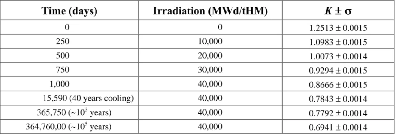
The results for the F 17*17 PWR assembly containing no burnable poison are given in Tables 7 and 8. Table 7 lists the variation of the neutron multiplication factor with irradiation
Table 5. Neutron multiplication factor as a function of irradiation and cooling time for the Svea 100 BWR fuel assembly containing burnable poison.
Time (days) Irradiation (MWd/tHM) K ±±σσ
0 0 1.0648 ± 0.0023 3 75 1.0417 ± 0.0024 10 250 1.0378 ± 0.0023 25 625 1.0426 ± 0.0023 40 1,000 1.0530 ± 0.0025 120 3,000 1.0765 ± 0.0024 200 5,000 1.1130 ± 0.0024 300 7,500 1.1387 ± 0.0025 400 10,000 1.1482 ± 0.0025 800 20,000 1.0672 ± 0.0022 1,200 30,000 0.9809 ± 0.0024 1,600 40,000 0.9134 ± 0.0021 16,190 (40 years cooling) 40,000 0.8344 ± 0.0021
Table 6. Results of repository calculation for canisters containing Svea 100 BWR assemblies. The reference case is highlighted.
Case Description K σσ K ++ 3σσ
9 Assemblies containing unirradiated fuel of
average enrichment 3.3 wt% in 90 pins. There are 10 pins with burnable poison (3.15 wt%
Gd2O3) at enrichment of 3.21 wt%. The
canisters contain water.
0.7067 0.0010 0.7097
10 As Case 9, but with a fuel burnup of 40,000 MWd/tHM and 40 years cooling time before disposal.
0.5982 0.0010 0.6012
11 As Case 9, but with a fuel burnup of 10,000
MWd/tHM and no cooling time.
Table 7. Neutron multiplication factor as a function of irradiation and cooling time for the F 17*17 PWR fuel assembly with no burnable poison.
Time (days) Irradiation (MWd/tHM) K ±±σσ
0 0 1.2513 ± 0.0015 250 10,000 1.0983 ± 0.0015 500 20,000 1.0073 ± 0.0014 750 30,000 0.9294 ± 0.0015 1,000 40,000 0.8666 ± 0.0015 15,590 (40 years cooling) 40,000 0.7843 ± 0.0014 365,750 (~103 years) 40,000 0.7792 ± 0.0014 364,760,00 (~105 years) 40,000 0.6941 ± 0.0014
Table 8. Results of repository calculation for canisters containing F 17*17 PWR assemblies with no burnable poison. The reference case is highlighted.
Case Description K σσ K ++ 3σσ
12 Assemblies containing unirradiated fuel of
average enrichment 3.17 wt%. The canisters contained no water. The thickness of cast iron between adjacent canister inserts was 130 mm.
0.2110 0.0008 0.2134
13 As Case 12, but the canister void space
contained water.
0.9731 0.0010 0.9761
14 As Case 13, but the fuel had an average
initial enrichment of 3.7 wt%.
1.0063 0.0010 1.0093
15 As Case 13, but the thickness of cast iron
between adjacent canister inserts was 80 mm.
0.9895 0.0010 0.9925
16 As Case 13, but with a fuel burnup of 40,000 MWd/tHM and 40 years cooling time before disposal.
Table 8 shows the calculated neutron multiplication factor for a disposal canister containing 4 F 17*17 PWR assemblies under repository conditions (representing about 2.1 x 10³ kg of original enriched uranium). Canisters containing dry fuel (Case 12) were subcritical. Inclusion of water resulted in a large increase in the neutron multiplication factor. The canisters containing unirradiated fuel (Case 13) failed to meet the safety criterion discussed at the start of Section 3.2. The neutron multiplication factor was greater than one for Case 14, in which the initial average enrichment was increased to 3.7%; Werme (1998) listed a maximum enrichment of 4.2% for PWR fuel.
For Cases 12 to 14, the thickness of cast iron between the fuel channels was 130 mm, which is consistent with the design discussed by Werme (1998). For Case 15, the thickness of cast iron between the fuel channels was reduced to 80 mm, to be consistent with the design presented by Andersson (1998) and shown in Figure 2. As a result, for Case 15, the reactivity increased slightly compared to Case 13. Canisters containing fuel irradiated to 40,000 MWd/tHM had a large margin of subcriticality (Case 16, the reference case for this assembly). For the reference case, each PWR canister contained 10.2 kg of 239Pu.
3.2.4 F 17*17 PWR Assembly Containing Burnable Poison
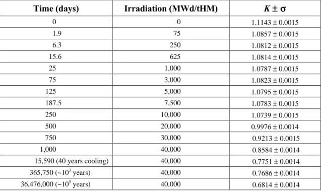
The results for the F 17*17 PWR assembly containing burnable poison are given in Tables 9 and 10. Table 9 lists the variation of the neutron multiplication factor with irradiation and subsequent cooling. The burnable poison stabilized the neutron multiplication factor. As the burnable poison was used, the depletion of the fissile species and further fission product formation resulted in a decrease in the neutron multiplication factor.
Table 10 shows the calculated neutron multiplication factor for disposal canisters containing 4 F 17*17 PWR assemblies with burnable poisons, under repository conditions. Canisters containing unirradiated fuel remained subcritical when water was included in the canister void space (Case 17). The largest neutron multiplication factor occurred for canisters containing fuel with a burnup of 7,500 MWd/tHM (Case 18). Canisters containing fuel irradiated to 40,000 MWd/tHM had a large margin of subcriticality (Case 19, the reference case for this assembly).
3.2.5 MOX BWR Assembly
The results for the MOX assembly are given in Tables 11 and 12. Table 11 lists the variation of the neutron multiplication factor with irradiation and subsequent cooling. As irradiation increased, the neutron multiplication factor decreased and, thus, the most reactive state for the assembly was when the fuel was unirradiated. Table 12 shows the calculated neutron multiplication factor for a disposal canister containing MOX assemblies under repository
Table 9. Neutron multiplication factor as a function of irradiation and cooling time for the F 17*17 PWR fuel assembly containing burnable poison.
Time (days) Irradiation (MWd/tHM) K ±±σσ
0 0 1.1143 ± 0.0015 1.9 75 1.0857 ± 0.0015 6.3 250 1.0812 ± 0.0015 15.6 625 1.0814 ± 0.0015 25 1,000 1.0787 ± 0.0015 75 3,000 1.0823 ± 0.0015 125 5,000 1.0795 ± 0.0015 187.5 7,500 1.0783 ± 0.0015 250 10,000 1.0739 ± 0.0015 500 20,000 0.9976 ± 0.0014 750 30,000 0.9213 ± 0.0015 1,000 40,000 0.8584 ± 0.0014 15,590 (40 years cooling) 40,000 0.7751 ± 0.0014 365,750 (~103 years) 40,000 0.7686 ± 0.0014 36,476,000 (~105 years) 40,000 0.6814 ± 0.0014
Table 10. Results of repository calculation for canisters containing F 17*17 PWR assemblies with burnable poisons. The reference case is highlighted.
Case Description K σσ K ++ 3σσ
17 Assembly containing unirradiated fuel of
average enrichment 3.17 wt% in pins without burnable poison and an enrichment of 1.38 wt% in the 12 pins with burnable poison (3.85 wt% Gd2O3). The canister void space
contained water.
0.8595 0.0010 0.8625
18 As Case 17, but with a fuel burnup at 7,500
MWd/tHM.
0.8804 0.0010 0.8834
19 As Case 17, but with a fuel burnup at 40,000 MWd/tHM and 40 years cooling time before disposal.
Table 11. Neutron multiplication factor as a function of irradiation and cooling time for the MOX BWR fuel assembly.
Time (days) Irradiation (MWd/tHM) K ±±σσ
0 0 1.1891 ± 0.0024 400 10,000 1.0915 ± 0.0025 800 20,000 1.0376 ± 0.0023 1,200 30,000 0.9842 ± 0.0023 1,600 40,000 0.9395 ± 0.0024 16,190 (40 years cooling) 40,000 0.7575 ± 0.0024 366,350 (103 years) 40,000 0.7385 ± 0.0024 36,476,600 (105 years) 40,000 0.6717 ± 0.0022
Table 12. Results of repository calculation for canisters containing MOX BWR assemblies.
Case Description K σσ K ++ 3σσ
20 Assemblies containing unirradiated MOX
fuel as defined in Section 3.1.1.5. The canister void space contained water.
0.8336 0.0010 0.8366
3.3 Summary
The reactivity of BWR and PWR spent fuel canisters under possible repository conditions has been calculated. The reference case for each fuel type assumed a burnup of 40,000 MWd/tHM, a 40-year storage period prior to disposal, and canister failure immediately after disposal. Canister failure (resulting in water entering the canister) caused a substantial increase in the neutron multiplication factor. However, under reference conditions, all canisters exhibited a large margin of subcriticality. The canister containing F 17*17 PWR assemblies with no burnable poison was marginally the most reactive canister under these conditions, with K = 0.6937.
The highest neutron multiplication factors calculated for each canister, and the corresponding conditions, are shown in Table 13. Only failed canisters containing unirradiated PWR assemblies with no burnable poison pins exhibited an inadequate margin of subcriticality.
Table 13. Highest calculated neutron multiplication factors for each type of canister, and assumed conditions.
Canister contents Conditions K
Svea 64 BWR assemblies Unirradiated fuel
Canister failure No cooling time
0.8318
Svea 100 BWR assemblies (with burnable poison)
Burnup of 10,000 MWd/tHM Canister failure
No cooling time
0.7936
F 17*17 PWR assemblies Unirradiated fuel
Canister failure No cooling time
1.0063
F 17*17 PWR assemblies (with burnable poison)
Burnup of 7,500 MWd/tHM Canister failure
No cooling time
4 Review of Previous Criticality Analyses
The spent-fuel repository development programme in Sweden has included criticality studies by Behrenz and Hannerz (1978) and Oversby (1996). Behrenz and Hannerz (1978) evaluated the likelihood and possible consequences of a criticality incident involving either
239
Pu or 235U following canister failure. Oversby (1996) re-evaluated the analysis by Behrenz and Hannerz (1978) in the context of changes in canister design. Oversby (1996) included an assessment of the potential for criticality based on an application of results from studies of natural uranium deposits at Oklo in Gabon, Africa. A review of these criticality studies is presented in this section.
4.1 Canister Design
The disposal concepts assumed by Behrenz and Hannerz (1978) and Oversby (1996) are similar to the current concept (summarized in Section 2), although there are differences in canister design and spent fuel capacity. Key canister design features adopted in each study are summarized in Table 14. Notably, the thickness of the copper canister was 200 mm in the Behrenz and Hannerz (1978) study and is 50 mm in the current study, but the current concept of using a cast insert is similar to that assumed by Behrenz and Hannerz (1978). Also, according to the calculations reported in Section 3 of this report, a canister manufactured to the current design would contain more spent fuel than the canisters considered by Behrenz and Hannerz (1978) and Oversby (1996). The significance of the various design differences is discussed in the following subsections.
4.2 Plutonium Criticality
Behrenz and Hannerz (1978) considered that a criticality incident could involve either 239Pu or 235U (after the decay of 239Pu), but in each case canister failure is required. Under optimum conditions, just a few hundred grams of plutonium are needed to form a critical
mass. Behrenz and Hannerz (1978) estimated that the mass of 239Pu in a PWR canister
would have reduced from about 9.4 kg at the time of disposal (assuming a burnup of 33,000 MWd/tU) to about 0.5 kg after 105 years. Thus, failure of a single canister and inflow of water within the first 105 years after disposal could theoretically result in plutonium criticality. Similarly, accumulation of plutonium outside a failed canister could result in criticality. Behrenz and Hannerz (1978) considered that corrosion was unlikely to result in canister failure before 105 years. Also, if the repository were located in a seismically and tectonically stable setting, mechanical failure of canisters would be unlikely. Thus, early canister failure by some other means, such as a material defect, would be required for
Table 14. Canister designs assumed in criticality studies.
Study Spent fuel and canister descriptions
Behrenz and Hannerz (1978)
Canister 200-mm thick, 4.7-m long, 0.77-m diameter, copper.
Free space filled with lead cast into place.
Spent fuel content 498 BWR fuel rods or 744 PWR fuel rods. A PWR
canister would contain an initial mass of 9.4 kg of 239Pu, assuming a burnup of 33,000 MWd/tU of a total of about 1.4 x 10³ kg of original enriched uranium.
Oversby (1996)
Canister 50-mm thick, 4.94-m long, 0.89-m diameter, copper. An
inner 50-mm thick steel section provides structural strength. Space between the fuel pins filled with a solid material, such as glass beads (SKB, 1994).
50-mm thick, 4.85-m long, 1.05-m diameter, copper. Cast solid insert (iron, steel or a non-ferrous metal), with rectangular channels for the fuel assemblies (SKB, 1996).
Spent fuel content 12 BWR fuel assemblies or 4 PWR fuel assemblies. A
BWR canister would contain 9.8 kg of 239Pu, assuming a burnup of 35,000 MWd/tHM of a total of about 2.0 x 10³ kg of original enriched uranium (about 3% enriched
235
U).
Current study
Canister 50-mm thick, 4.83-m long, 1.05-m diameter, copper.
Nodular cast iron insert with steel cassette for fuel assemblies and cooling channels.
Spent fuel content 12 BWR fuel assemblies or 4 PWR fuel assemblies. A
PWR canister contains 10.2 kg of 239Pu, assuming a
burnup of 40,000 MWd/tHM of about 2.1 x 10³ kg of
original enriched uranium (3.17 % enriched 235U). A BWR canister contains 12.5 kg of 239Pu, assuming a
Behrenz and Hannerz (1978) performed a series of calculations to determine whether plutonium criticality inside a container or in the bentonite buffer was possible if early canister failure did occur. They considered that plutonium criticality would require separation of plutonium from most of the other constituents of the irradiated fuel and concentration of plutonium in a region containing sufficient water for neutron moderation.
4.2.1 Plutonium Criticality Inside a Canister
Behrenz and Hannerz (1978) considered that plutonium criticality inside a canister requires the following combination of events and processes:
• A leak occurs in the canister wall soon after disposal.
• The canister partially corrodes but remains intact (forming porous copper oxide),
resisting bentonite expansion.
• The lead filling and zircaloy tubes in the canister corrode (but remain intact with no transport or expansion of corrosion products), and leak sufficiently to allow water to reach the fuel rods and to create a migration pathway.
• Water radiolysis in the fuel zone generates H2, which leaves as gas, and O2 and H2O2,
which cause oxidation of the spent fuel and canister materials.
• Uranium is oxidized to the hexavalent stage and leaves the porous canister as a
hexavalent carbonate complex. Insoluble fission products (e.g., rare earths) are also extracted from the canister.
• The volume occupied by uranium in the canister is replaced by water, but bentonite
does not expand into this volume.
• Plutonium oxide remains in the canister as a slurry in tetravalent form.
Behrenz and Hannerz (1978) calculated the infinite neutron multiplication factor for spent fuel rods under the above conditions using the ASEA-ATOM code, MICØ. The fuel rods were modelled as a lattice of tubes containing plutonium-oxide slurry in water at different plutonium densities. This configuration appears reasonably representative of the current canister design, although Behrenz and Hannerz (1978) did not provide sufficient information to determine the significance of differences in fuel rod arrangements and dimensions. There may be a greater separation between fuel assemblies in the current design, which would have the effect of reducing the neutron multiplication factor.
Calculations were performed at different times up to 5x10⁴ years after disposal to account
the water is high and neutron leakage is low. Most calculations were performed for plutonium densities of 50 kg m-3 and 100 kg m-3. The minimum height of the plutonium-oxide slurry in the canister required to achieve criticality was calculated at each time as a function of plutonium density in the water.
Behrenz and Hannerz (1978) then considered whether critical heights of plutonium-oxide slurry could be achieved in the canister based on estimates of the possible rate of removal of UO2 from the canister. Uranium was assumed to be removed from the top of the canister
as uranyl carbonate complex by diffusion through the buffer material to the tunnel and to fractures in the host-rock. The diffusion calculations were based on a reasonably high U(VI) solubility of 1,070 g m-3 in the water at the upper surface of the canister, a buffer diffusivity of 8 x 10-11 m2s-1, and a fracture frequency of 2.5 m-1 in the host-rock, with a fracture aperture of 0.2 mm (implying an effective hydraulic conductivity of the order of 10-5 ms-1). Behrenz and Hannerz (1978) calculated that uranium would enter the host rock fractures at a rate of about 3 x 10⁻³ kg year-1, and would enter the tunnel at a rate of 2 x 10⁻³ kg year-1. The current canisters have a larger upper surface area, and contain a greater number of fuel rods, than those considered by Behrenz and Hannerz (1978). These differences imply that the diffusion model would predict a greater rate of removal of uranium from the top of the canister, although Behrenz and Hannerz (1978) did not provide sufficient information to quantify this possible difference.
A total of 100 kg of U(VI) was assumed to be held up in solution in the bentonite (although the basis for this value was not presented), and some precipitation of uranium following reduction to U(IV) was assumed to occur. The bentonite was assumed to contain 0.12% Fe(II), although bentonite typically contains iron in the oxidized state (Deer et al., 1966). Behrenz and Hannerz (1978) estimated that oxidation of the Fe(II) would correspond to reduction and precipitation of a maximum of 65 kg of U(IV). Under the design studied in Section 3.1.2 of this report, 21% more bentonite would be placed in the deposition hole than assumed by Behrenz and Hannerz (1978), which would imply a potential precipitation of 79 kg of U(IV). Similarly, the greater mass of bentonite may have a correspondingly greater absorption capacity.
The amount of plutonium remaining in the canister in particulate form at a specific time was estimated from the amount of UO2 removed and from the plutonium inventory at that time.
The results were converted to heights of plutonium-oxide slurry for different plutonium densities in the water. These heights were always smaller than the heights of material calculated to be required for criticality at equivalent times and plutonium densities, and Behrenz and Hannerz (1978) concluded that criticality under the prescribed conditions is not possible.
By inspection of the results presented by Behrenz and Hannerz (1978), it is apparent that the canister is closest to criticality at about 40,000 years after disposal. The mass of
from the canister, rather than by the total amount of fuel present. Based on these assumptions, plutonium criticality is unlikely to occur even if as much as 12.5 kg of 239Pu were placed in the canisters (as determined for current BWR canisters in Section 4.1). Behrenz and Hannerz (1978) considered that only if a substantial amount of bentonite were removed from the deposition hole, thus reducing the obstruction to flow, could sufficient uranium be removed from the canisters for plutonium criticality to occur in the canister. They also considered that the host-rock fracture apertures would be too small for significant bentonite loss to occur, and that the development of large fractures would be unlikely under the expected stable tectonic conditions.
4.2.2 Plutonium Criticality Outside a Canister
Plutonium criticality outside a canister requires plutonium dissolution within the canister and precipitation outside the canister. Dissolution of plutonium in preference to uranium is not feasible because uranium is generally more soluble than plutonium, and no complexing agents specific to plutonium are available. Thus, Behrenz and Hannerz (1978) assumed that uranium and plutonium are both transported from the canister and that plutonium precipitates preferentially from the diffused mixture in saturated bentonite. Criticality calculations assumed a bentonite-PuO2 mixture of spherical geometry in a
saturated bentonite with a bulk density of 1.95x10³ kg m-3 and a water content of 29.6%. The calculated mass of plutonium required for criticality decreased from 5.3 kg initially at a concentration of 50 kg m-3 to a minimum of 2.2 kg after 60,000 years at a concentration of 40 kg m-3. The critical mass of 239Pu initially decreased with time because the neutron absorber, 240Pu, has a shorter half-life than 239Pu. Based on calculated rates of removal from the canister, insufficient plutonium (a maximum of about 1 kg) will be available in the buffer at any time for a critical mass to be formed.
By inspection of the results presented by Behrenz and Hannerz (1978), it is apparent that the modelled configuration is closest to critical conditions at about 30,000 years after disposal. The mass of plutonium in the bentonite-PuO2 mixture would need to increase by
a factor of almost 2.6 for criticality to occur at 30,000 years, which implies that the canister would initially need to contain at least 24 kg of 239Pu. However, because the rate of removal of plutonium from the canister was assumed to be limited by the rate of removal of UO2,
plutonium criticality would not occur even if greater quantities of fuel were placed in the canisters. Based on these assumptions, plutonium criticality in the bentonite is unlikely to occur for canisters packaged according to current designs.
Behrenz and Hannerz (1978) did not give any specific consideration to plutonium transport in colloidal form, and its effects on the potential for criticality. Any colloids present in the vicinity of a canister would most likely be immobilized by the compacted bentonite (Savage et al., 1999). Furthermore, because the analysis assumed the rate of removal of plutonium
Behrenz and Hannerz (1978) considered that only if the bentonite were removed could a critical mass be formed. The critical mass of 239Pu, assuming total bentonite removal, is about 0.5 kg.
Behrenz and Hannerz (1978) also determined that the energy generated by criticality in a deposition hole would be insignificant. If a critical assembly formed after 20,000 years, it could generate no more than about 7 % of the total energy released by the spent fuel in the canister. The maximum temperature achievable in the critical region before water expulsion causes the reactor to shut down would be about 265°C, and the temperature would only be sustained for a maximum of 300 years.
4.2.3 Autocatalytic Criticality
Oversby (1996) considered the potential for autocatalytic criticality to occur in a KBS-3 repository, by comparison with the analysis of Bowman and Venneri (1996). Bowman and Venneri (1996) claimed that autocatalytic criticality and explosive conditions could be reached for 239Pu in a mixture of water and silica, with the system embedded in an infinite silica medium to act as a neutron reflector. Accumulation of a critical mass of 239Pu was assumed to result from its redeposition in a spherical geometry in a medium containing different ratios of silica and water. Criticality with positive feedback (autocatalytic) is possible under dry conditions if at least 50 kg of 239Pu is dispersed in a 200-cm radius sphere containing about 70,000 kg of silica. Water is required to achieve criticality in smaller spheres, and negative feedback conditions are reached as water is expelled. Thus, as concluded by Oversby (1996), criticality under dry conditions is unlikely to occur because it would require the concentration of plutonium from several canisters at one location.
4.3 Uranium Criticality
Behrenz and Hannerz (1978) noted that the initial enrichment of uranium (with burn-up of 35,000 MWd/tU or more) is too low for 235U criticality to occur, but in-growth from decay of 239Pu and 243Am will increase 235U to a level where a criticality incident is theoretically possible (after about 10,000 years). However, uranium from many canisters would need to accumulate in one location, such as the deposition holes or tunnels and shafts of the repository, to form a critical assembly. Behrenz and Hannerz (1978) considered that uranium criticality is not possible in fractures in the host rock for geometric reasons, which is consistent with the findings of criticality assessments undertaken by other radioactive waste disposal projects (Hicks and Green, 1999). Further, Behrenz and Hannerz (1978) noted that the reducing conditions of the deep ground water of the Fennoscandian Shield
4.3.1 Uranium Criticality in a Tunnel
Behrenz and Hannerz (1978) calculated a minimum critical mass of 4,400 kg of uranium (1.66% enriched) in a tunnel, assuming a spherical geometry (radius 0.9 m, volume 3.5 m3), requiring uranium from at least four canisters. Uranium from at least two canisters would be required assuming the more recent canister designs.
For criticality to occur in the tunnels (filled with sand and bentonite), the uranium must be transported into the tunnels in the hexavalent soluble form, where it must be reduced to the almost completely insoluble tetravalent form. However, this process is likely to be limited by the length of time over which radiolysis generates oxidizing conditions in the vicinity of the canisters after disposal, unless localized intrusion of oxidizing groundwaters occurred. Oversby (1996) also noted that the presence of iron in the canisters would reduce the likelihood of uranium oxidation occuring if oxidizing water entered the canister. Preferential oxidation of iron to Fe(II) and/or Fe(III) would reduce the potential for uranium oxidation.
Behrenz and Hannerz (1978) assumed oxidizing waters existed in the long term near the canisters, and estimated that U(VI) could be transported 10 m in the filled tunnel in 107 years under a hydraulic gradient of 1%. Their analysis assumed a tunnel hydraulic conductivity of 10-9 m2s-1, and their results imply that a uranium retardation factor of the order of 100 was assumed. Behrenz and Hannerz (1978) noted that the average uranium diffusion distance in the tunnel would also be about 10 m. Behrenz and Hannerz (1978) concluded that a critical mass could not be formed in the tunnel as a result of such migration processes. The hydraulic conductivity and uranium diffusivity assumed by Behrenz and Hannerz (1978) are consistent with those listed by Bennett et al. (1998) for a repository tunnel fill comprising 85% sand and 15% bentonite (hydraulic conductivity of 10-9 - 10-11 m2s-1 and effective diffusivity of about 10-10 m2s-1).
Behrenz and Hannerz (1978) performed calculations assuming 227,000 kg of uranium (1.66% enriched 235U) from all 160 deposition holes in one tunnel (a cylinder with radius 1.85 m and length 27 m) forms a critical configuration at a uranium density of 780 kgU m-3. The power of a reactor of this configuration would be less than 130 kW. An upper limit of the energy generated by such a reactor before it shuts down due to depletion of fissile material would be 3x10⁶ MWd, which would be equal to the burn-up of about 900,000 kg of disposed power reactor fuel. Behrenz and Hannerz (1978) considered that the energy generation would be distributed over at least 100,000 years, and the release of radionuclides to the groundwater would be equivalent to less than one failed canister every 1,000 years. The amount of long-lived fission products and radionuclides formed would be about 10% of the original repository inventory.
As long as the bentonite remains in the deposition holes, uranium from several canisters would need to accumulate in one hole for a critical mass to form, which Behrenz and Hannerz (1978) considered unlikely. For uranium criticality to occur involving the content of one canister, about 45% of the bentonite would need to be lost from the top of the borehole and replaced with water. In this case, uranium criticality would require a series of processes to occur: diffusion of U(VI) from the canister under local oxidizing conditions into the upper part of the borehole where reducing conditions existed; diffusion of Fe(II) from the tunnel into the upper part of the borehole; reduction of U(VI) to U(IV); and precipitation of U(IV) in the upper part of the borehole containing bentonite with a high water content. However, Behrenz and Hannerz (1978) considered that significant bentonite removal from the deposition holes was unlikely to occur, and thus uranium criticality in the deposition holes was unlikely.
Behrenz and Hannerz (1978) also determined that the amount of fission products and radiotoxic heavy nuclides created in the event of criticality in the deposition holes would be about 40% of the initial inventory of nuclides in the canister.
4.3.3 Analogy with the Oklo Natural Reactors
The natural reactors in the uranium ore deposits at Oklo in Gabon, Africa, occurred over 2,000 million years ago. The uranium deposits formed as U(VI) was transported in hydrothermal solution and reduced to U(IV) when it came into contact with reducing hydrocarbons in localized fault traps in sandstone. The Oklo ore zones are typically 10 to 50 cm thick and have an average length and width of 10 m. The geometry and natural enrichment of some of the ore zones were such that criticality occurred about 2,000 million years ago.
Based on considerations of the amount of neutron absorbers in the fuel (rare earths), Oversby (1996) estimated that a minimum thickness of 120 cm of “ore” would be required to achieve an Oklo-type criticality for 1.62% enriched 235U. Oversby (1996) deduced that, for a canister with an inner diameter of 95 cm, the neutron absorbers in the fuel are sufficient to eliminate the possibility of criticality.
Oversby (1996) also considered the possibility of an Oklo-type criticality occurring in a disposal tunnel. Uranium migration was assumed from several canisters, each of which contains about 2,000 kg of fuel. The tunnel fill was assumed to be 85% sand and 15% bentonite, as in the KBS-3 concept. To achieve a critical geometry in the tunnel, sand must be replaced by water such that the porosity increases to about 55%, and sufficient uranium can enter the tunnel. Based on the distribution of materials assumed in the tunnel, and the minimum thickness of 120 cm (1.62% enriched 235U) of an Oklo-type reactor zone (with
5 Conclusions
Calculations have been undertaken to determine the possibility of criticality occurring in spent fuel disposal canisters based on current canister designs described in Section 2 of this report. The calculations involved determination of the neutron multiplication factor for various disposal configurations, depending on the type of canister and fuel assemblies, the initial fuel enrichment, the amount of fuel burn-up, and the amount of burnable poison present. In particular, canisters were assumed to fail at some time after disposal, such that water entered the canister and filled the voids, including the cooling tubes recently incorporated in the canister design.
Various BWR and PWR spent fuel assemblies were considered in the analyses presented in Section 3. The reference case for each fuel type assumed a burnup of 40,000 MWd/tHM, a 40-year storage period prior to disposal, and canister failure immediately after disposal. Under these conditions, canisters exhibited a large margin of subcriticality for each fuel type considered. Furthermore, the BWR canisters were found to be subcritical for all values of fuel burnup considered (including unirradiated fuel). Canisters containing PWR assemblies were also determined to be subcritical for all values of burnup, provided that burnable poison pins were present. However, if burnable poison pins were not present, then canisters containing unirradiated PWR assemblies were found to have an inadequate margin of subcriticality. Further analysis could be undertaken to determine the relationship between fuel burnup and the neutron moderation factor for canisters containing PWR fuel without burnable poison.
In general, for criticality to occur following disposal of canisters containing typical irradiated BWR and PWR fuel, fissile material would need to become concentrated in a moderating environment in the repository. The spent-fuel repository development programme in Sweden has included criticality studies by Behrenz and Hannerz (1978) and Oversby (1996) which investigated such scenarios. These studies focused on evaluating plutonium and uranium criticality excursions in which fissile material became concentrated at various locations in the repository (canister, deposition hole, or tunnel) following canister failure. The studies determined that insufficient fissile material could accumulate anywhere in the repository for a critical assembly to form and, even if criticality did occur, the consequences on safety would be insignificant.
The approaches taken by Behrenz and Hannerz (1978) and Oversby (1996) to assessing the probability and consequences of criticality are similar to approaches taken in other repository programmes (Hicks and Green, 1999). Furthermore, these approaches are, in general, appropriate for the current disposal concept in Sweden, although there are several uncertainties concerning details of the analyses.
• The approach undertaken by Behrenz and Hannerz (1978) involved calculation of critical masses of plutonium slurry in failed canisters. The analyses depended on the arrangements and dimensions of fuel rods in the canisters, although values of these parameters were not provided. The arrangement of fuel rods in SKB’s current canister design differs from that assumed by Behrenz and Hannerz (1978); the sensitivity of the neutron multiplication factor to these parameters is uncertain.
• Uranium transport calculations by Behrenz and Hannerz (1978) assumed uranium to
be removed from the top of a canister and to migrate by diffusion through the buffer to the tunnel and to fractures in the host-rock. Reasonably conservative values of uranium solubility, bentonite diffusivity, and effective host rock hydraulic conductivity were used. However, the current reference canisters have a larger upper surface area and contain a greater number of fuel rods than those considered by Behrenz and Hannerz (1978). Although Behrenz and Hannerz (1978) did not provide details of their diffusion model, these differences suggest that the model would predict a greater rate of removal of uranium from the top of the canister. An increased rate of uranium removal would imply an increased potential for criticality in the canisters, deposition holes, and tunnels according to the scenarios considered by Behrenz and Hannerz (1978).
• The uranium transport calculations also required information on the amount of uranium that could be retained in the bentonite buffer as a result of absorption and precipitation. Behrenz and Hannerz (1978) did not provide information on the basis for determining the mass of uranium absorbed in the bentonite although, presumably, this depended on the volume of bentonite in the deposition hole. Calculation of the amount of uranium that could be precipitated in the bentonite depended on the amount of ferrous iron in the bentonite. Under the current canister design, a greater mass of bentonite would be placed in the deposition hole, which implies that more uranium could be absorbed and precipitated.
In conclusion, review of past criticality analyses has found that the approaches used and the results obtained are, in general, applicable to the current disposal concept in Sweden. Although several uncertainties exist concerning the details of the previous analyses, it is unlikely that recent modifications to the canister design will have any substantial effects on the findings of the earlier work. However, the remaining uncertainties, listed above, require further attention to confirm this conclusion.